at control NISSAN PATROL 1998 Y61 / 5.G Electrical System Workshop Manual
[x] Cancel search | Manufacturer: NISSAN, Model Year: 1998, Model line: PATROL, Model: NISSAN PATROL 1998 Y61 / 5.GPages: 326, PDF Size: 11.36 MB
Page 1 of 326
ELECTRICAL SYSTEM
SECTION
EL
When you read wiring diagrams:
+Read GI section, ``HOW TO READ WIRING DIAGRAMS''.
When you perform trouble diagnoses, read GI section, ``HOW TO FOLLOW FLOW
CHART IN TROUBLE DIAGNOSES'' and ``HOW TO PERFORM EFFICIENT DIAGNOSIS
FOR AN ELECTRICAL INCIDENT''.
+Check for any service bulletins before servicing the vehicle.
CONTENTS
PRECAUTIONS...............................................................1
Supplemental Restraint System (SRS) ``AIR
BAG'' and ``SEAT BELT PRE-TENSIONER''...............1
HARNESS CONNECTOR................................................2
Description ...................................................................2
STANDARDIZED RELAY................................................3
Description ...................................................................3
POWER SUPPLY ROUTING...........................................5
Schematic ....................................................................5
Wiring Diagram Ð POWER Ð....................................6
Fuse ...........................................................................14
Fusible Link................................................................14
Circuit Breaker Inspection .........................................14
GROUND DISTRIBUTION/LHD MODELS....................15
Engine Room Harness ..............................................15
Main Harness.............................................................19
Body Harness ............................................................22
Body No. 2 Harness ..................................................23
Back Door and Rear Window Defogger Harness .....24
Room Lamp Harness.................................................25
GROUND DISTRIBUTION/RHD MODELS...................26
Engine Room Harness ..............................................26
Main Harness.............................................................30
Body Harness ............................................................33
Body No. 2 Harness ..................................................34
Back Door and Rear Window Defogger Harness .....35
Room Lamp Harness.................................................36
BATTERY.......................................................................37
How to Handle Battery ..............................................37
Battery Test and Charging Chart ...............................40
Service Data and Speci®cations (SDS).....................44
STARTING SYSTEM.....................................................45
Wiring Diagram Ð START Ð ....................................45Trouble Diagnoses.....................................................46
Construction ...............................................................47
Removal and Installation ...........................................47
Inspection...................................................................47
Assembly ...................................................................50
Service Data and Speci®cations (SDS).....................51
CHARGING SYSTEM....................................................52
Wiring Diagram Ð CHARGE Ð ................................52
Trouble Diagnoses.....................................................53
Construction ...............................................................54
Removal and Installation ...........................................54
Disassembly...............................................................54
Inspection...................................................................55
Assembly ...................................................................56
Service Data and Speci®cations (SDS).....................56
COMBINATION SWITCH...............................................57
Check .........................................................................57
Replacement ..............................................................58
STEERING SWITCH......................................................59
Check .........................................................................59
HEADLAMP Ð Conventional Type Ð........................61
Wiring Diagram Ð H/LAMP Ð ..................................61
Trouble Diagnoses.....................................................62
Bulb Replacement .....................................................63
Aiming Adjustment .....................................................63
HEADLAMP Ð Daytime Light System Ð..................65
System Description ....................................................65
Wiring Diagram Ð DTRL Ð ......................................67
Trouble Diagnoses.....................................................69
Bulb Replacement .....................................................69
Aiming Adjustment .....................................................69
HEADLAMP Ð Headlamp Aiming Control Ð............70
System Description ....................................................70
EL
Page 3 of 326
Wiring Diagram Ð P/ANT Ð/LHD Models..............181
Wiring Diagram Ð P/ANT Ð/RHD Models .............182
Trouble Diagnoses...................................................183
Location of Antenna .................................................183
Antenna Rod Replacement .....................................183
Window Antenna Repair ..........................................184
ELECTRIC SUNROOF................................................186
Wiring Diagram Ð SROOF Ð ................................186
POWER DOOR MIRROR............................................188
Wiring Diagram Ð MIRROR Ð/LHD Models..........188
Wiring Diagram Ð MIRROR Ð/RHD Models .........189
POWER SEAT.............................................................190
Wiring Diagram Ð SEAT Ð/LHD Models ...............190
Wiring Diagram Ð SEAT Ð/RHD Models...............192
HEATED SEAT............................................................194
Wiring Diagram Ð HSEAT Ð..................................194
POWER WINDOW.......................................................196
System Description ..................................................196
Schematic ................................................................197
Wiring Diagram Ð WINDOW Ð .............................198
Trouble Diagnoses...................................................203
POWER DOOR LOCK.................................................204
System Description ..................................................204
Wiring Diagram Ð D/LOCK Ð ................................205
Trouble Diagnosis ....................................................207
POWER DOOR LOCK Ð Super Lock Ð.................. 211
Component Parts and Harness Connector
Location ................................................................... 211
System Description ..................................................212
Schematic ................................................................214
Wiring Diagram Ð S/LOCK Ð/LHD Models ...........215
Wiring Diagram Ð S/LOCK Ð/RHD Models ..........219
Trouble Diagnoses...................................................223
MULTI-REMOTE CONTROL SYSTEM.......................234
System Description ..................................................234
Wiring Diagram Ð MULTI Ð/LHD Models..............235
Trouble Diagnoses...................................................237
ID Code Entry Procedure ........................................239
NATS (Nissan Anti-Theft System)/LHD MODELS....240System Description ..................................................240
System Composition ................................................240
Wiring Diagram Ð NATS Ð ....................................241
CONSULT ................................................................242
Trouble Diagnoses...................................................244
How to Replace NATS IMMU ..................................253
NATS (Nissan Anti-Theft System)/RHD MODELS...254
Component Parts and Harness Connector
Location ...................................................................254
System Description ..................................................255
System Composition ................................................255
Wiring Diagram Ð NATS Ð ....................................256
CONSULT ................................................................257
Trouble Diagnoses...................................................259
LOCATION OF ELECTRICAL UNITS.........................269
Engine Compartment ...............................................269
Passenger Compartment Ð LHD Models ...............270
Passenger Compartment Ð RHD Models ..............272
HARNESS LAYOUT....................................................275
How to Read Harness Layout .................................275
Outline/LHD Models.................................................276
Outline/RHD Models ................................................277
Main Harness/LHD Models......................................278
Main Harness/RHD Models .....................................282
Engine Room Harness/LHD Models .......................286
Engine Room Harness/RHD Models .......................290
Engine Harness .......................................................294
Engine Control Harness and Alternator Harness ....295
Body Harness/LHD Models .....................................296
Body Harness/RHD Models.....................................300
Body No. 2 Harness/LHD Models ...........................304
Body No. 2 Harness/RHD Models...........................306
Chassis Harness......................................................308
Room Lamp Harness...............................................309
Front Door Harness (Driver side) ............................310
Front Door Harness (Passenger side) .................... 311
Rear Door Harness..................................................312
Back Door Harness and Rear Window Defogger
Harness....................................................................313
Page 69 of 326
System Description
OPERATION
Headlamp system on vehicles for North Europe contains a daytime light system. The unit operates to illumi-
nate headlamps low beam, parking, tail, license lamps and illuminations automatically in the following condi-
tions.
+The engine is running with lighting switch in OFF position.
When the any of following conditions exists, the daytime light operation will be canceled.
+Ignition switch is in any position other than ON
+Engine is stopped
+Lighting switch is turned to 1st or 2nd position.
If the daytime light system is canceled, lighting switch operations are the same as for conventional light sys-
tem.
DAYTIME LIGHT IS OPERATING
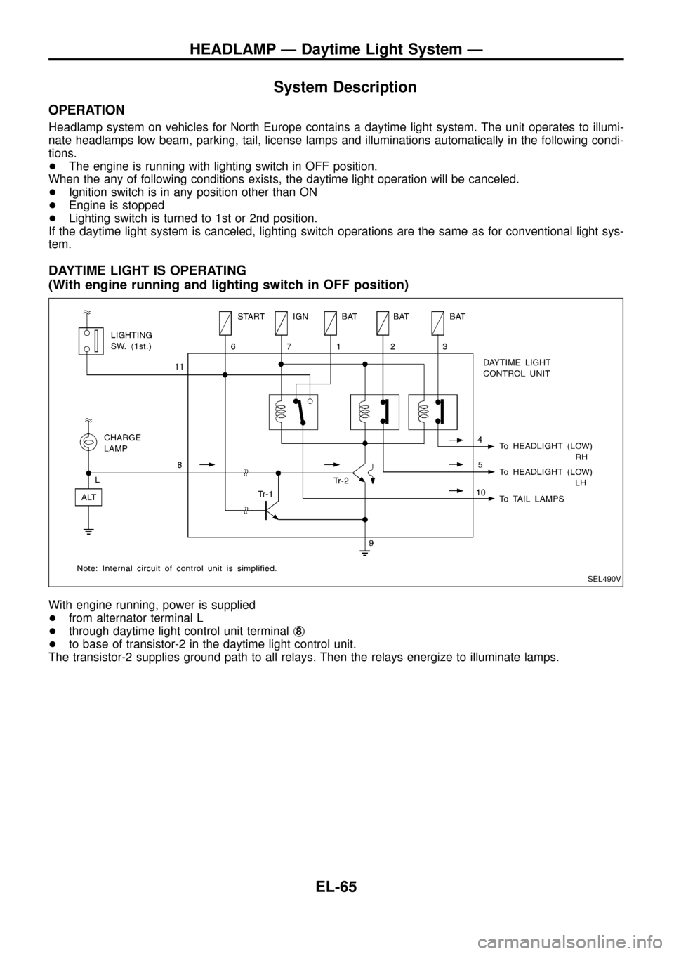
(With engine running and lighting switch in OFF position)
With engine running, power is supplied
+from alternator terminal L
+through daytime light control unit terminalj
8
+to base of transistor-2 in the daytime light control unit.
The transistor-2 supplies ground path to all relays. Then the relays energize to illuminate lamps.
SEL490V
HEADLAMP Ð Daytime Light System Ð
EL-65
Page 70 of 326
DAYTIME LIGHT IS CALCELED
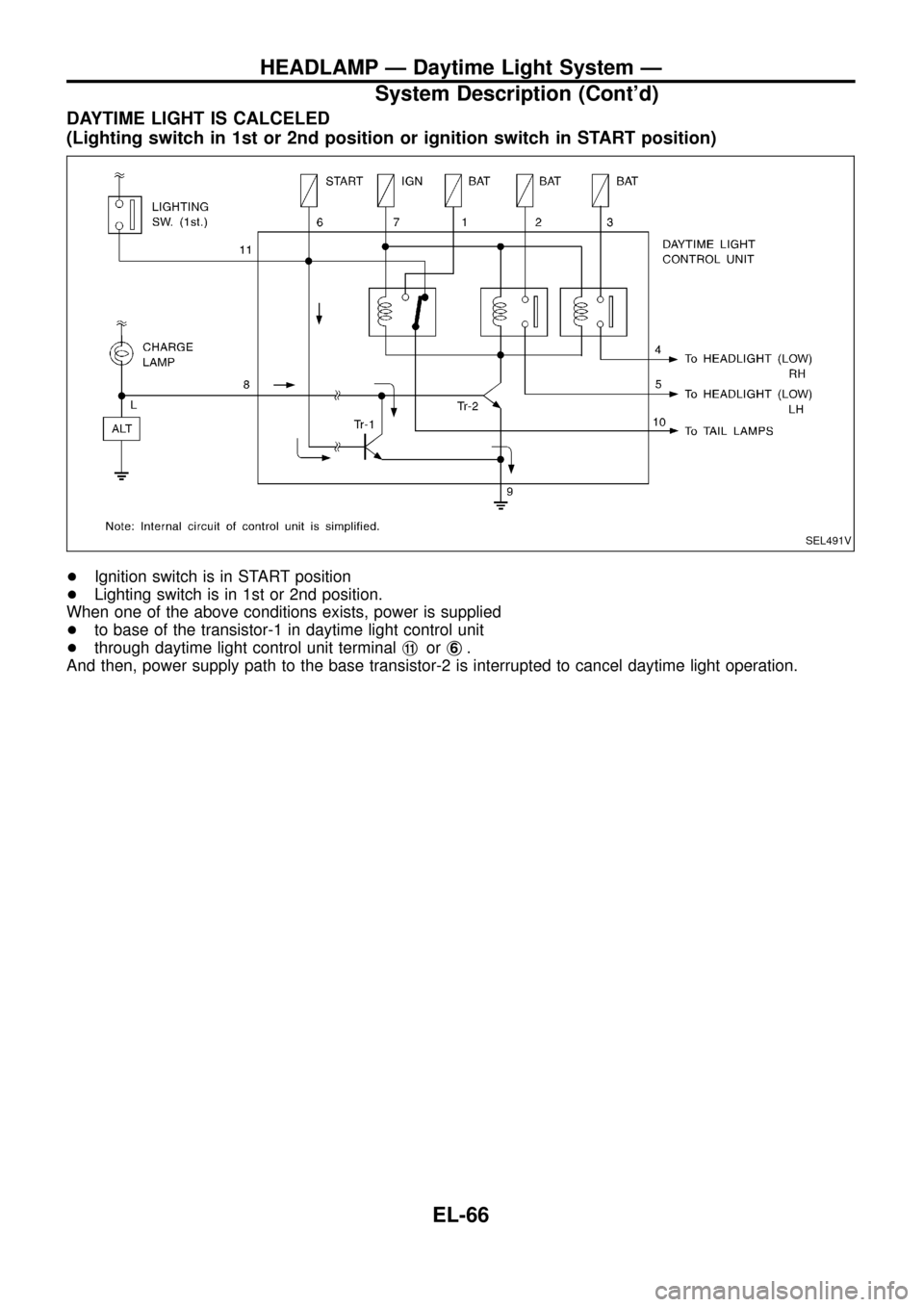
(Lighting switch in 1st or 2nd position or ignition switch in START position)
+Ignition switch is in START position
+Lighting switch is in 1st or 2nd position.
When one of the above conditions exists, power is supplied
+to base of the transistor-1 in daytime light control unit
+through daytime light control unit terminalj
11orj6.
And then, power supply path to the base transistor-2 is interrupted to cancel daytime light operation.
SEL491V
HEADLAMP Ð Daytime Light System Ð
System Description (Cont'd)
EL-66
Page 73 of 326
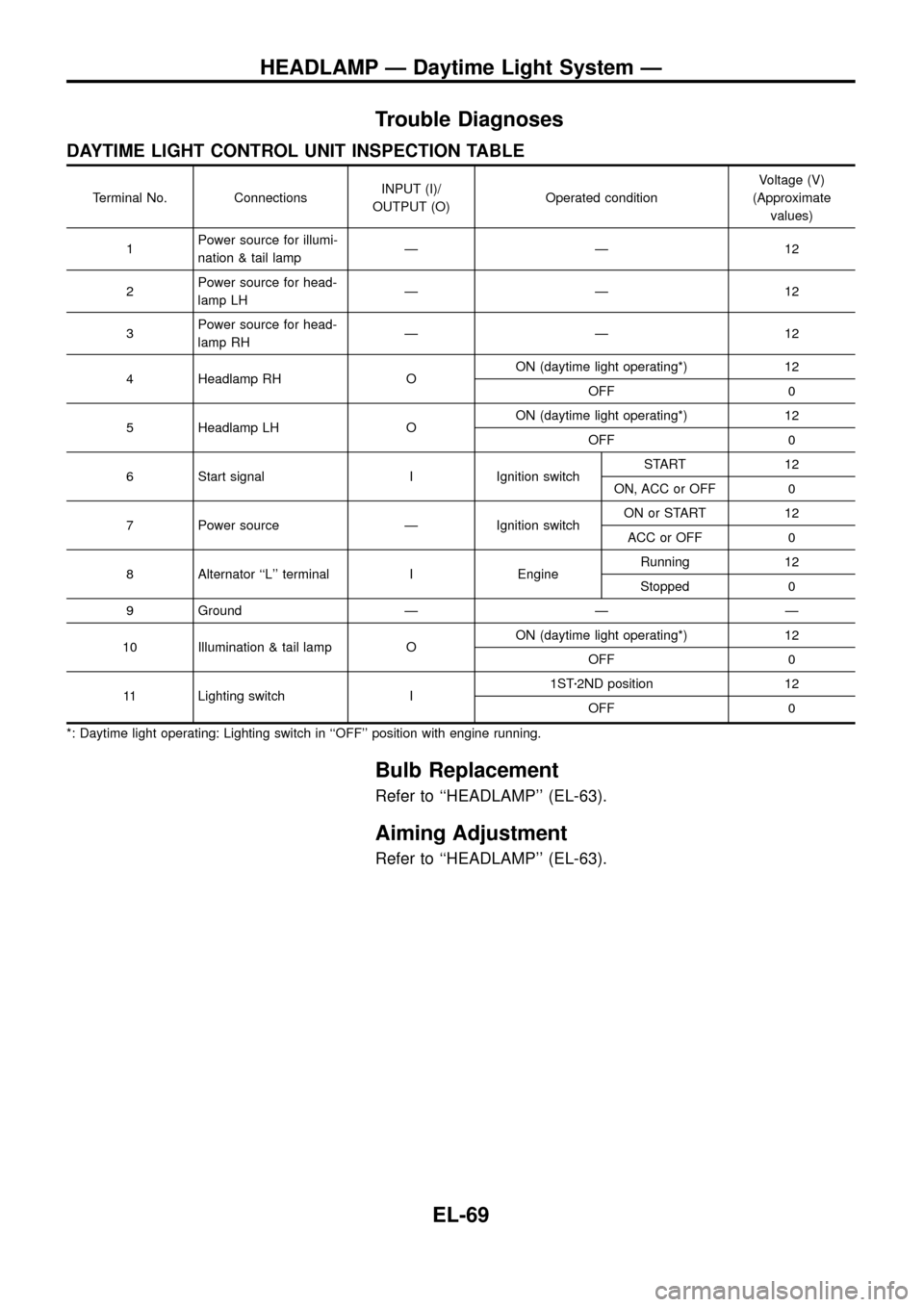
Trouble Diagnoses
DAYTIME LIGHT CONTROL UNIT INSPECTION TABLE
Terminal No. ConnectionsINPUT (I)/
OUTPUT (O)Operated conditionVoltage (V)
(Approximate
values)
1Power source for illumi-
nation & tail lampÐÐ12
2Power source for head-
lamp LHÐÐ12
3Power source for head-
lamp RHÐÐ12
4 Headlamp RH OON (daytime light operating*) 12
OFF 0
5 Headlamp LH OON (daytime light operating*) 12
OFF 0
6 Start signal I Ignition switchSTART 12
ON, ACC or OFF 0
7 Power source Ð Ignition switchON or START 12
ACC or OFF 0
8 Alternator ``L'' terminal I EngineRunning 12
Stopped 0
9 Ground Ð Ð Ð
10 Illumination & tail lamp OON (daytime light operating*) 12
OFF 0
11 Lighting switch I1STz2ND position 12
OFF 0
*: Daytime light operating: Lighting switch in ``OFF'' position with engine running.
Bulb Replacement
Refer to ``HEADLAMP'' (EL-63).
Aiming Adjustment
Refer to ``HEADLAMP'' (EL-63).
HEADLAMP Ð Daytime Light System Ð
EL-69
Page 74 of 326
![NISSAN PATROL 1998 Y61 / 5.G Electrical System Workshop Manual System Description
CIRCUIT OPERATION
[Example]
Aiming switch ``0
+When the aiming switch is set to ``0, the motor will not start.
This is because the power terminals are positioned at the non-
con NISSAN PATROL 1998 Y61 / 5.G Electrical System Workshop Manual System Description
CIRCUIT OPERATION
[Example]
Aiming switch ``0
+When the aiming switch is set to ``0, the motor will not start.
This is because the power terminals are positioned at the non-
con](/img/5/616/w960_616-73.png)
System Description
CIRCUIT OPERATION
[Example]
Aiming switch ``0''
+When the aiming switch is set to ``0'', the motor will not start.
This is because the power terminals are positioned at the non-
conductive section of the sensor's rotary unit.
Aiming switch ``0''®``1''
+When the aiming switch is moved from ``0'' to ``1'', the sensor's
conductive section activates the relay. Power is supplied
through the relay to the motor. The headlamps will then move
in the ``DOWN'' direction.
+The motor continues to rotate while the rotary unit of the sen-
sor moves from point A to point B.
+The power terminals will then be positioned at the nonconduc-
tive section, disconnecting the power to the motor. The motor
will then stop.
Aiming switch ``1''®``0''
+When the aiming switch is moved from ``1'' to ``0'', the sensor's
conductive section activates the relay. Power is supplied
through the relay to the motor. The motor will rotate to move the
headlamps in the ``UP'' direction.
+When the rotary unit of the sensor moves from point B to point
A, the motor will stop.
SEL465M
SEL364P
SEL365P
HEADLAMP Ð Headlamp Aiming Control Ð
EL-70
Page 75 of 326
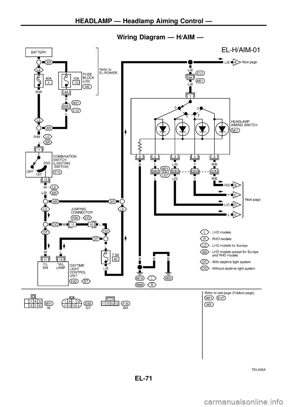
Wiring Diagram Ð H/AIM Ð
TEL406A
HEADLAMP Ð Headlamp Aiming Control Ð
EL-71
Page 76 of 326
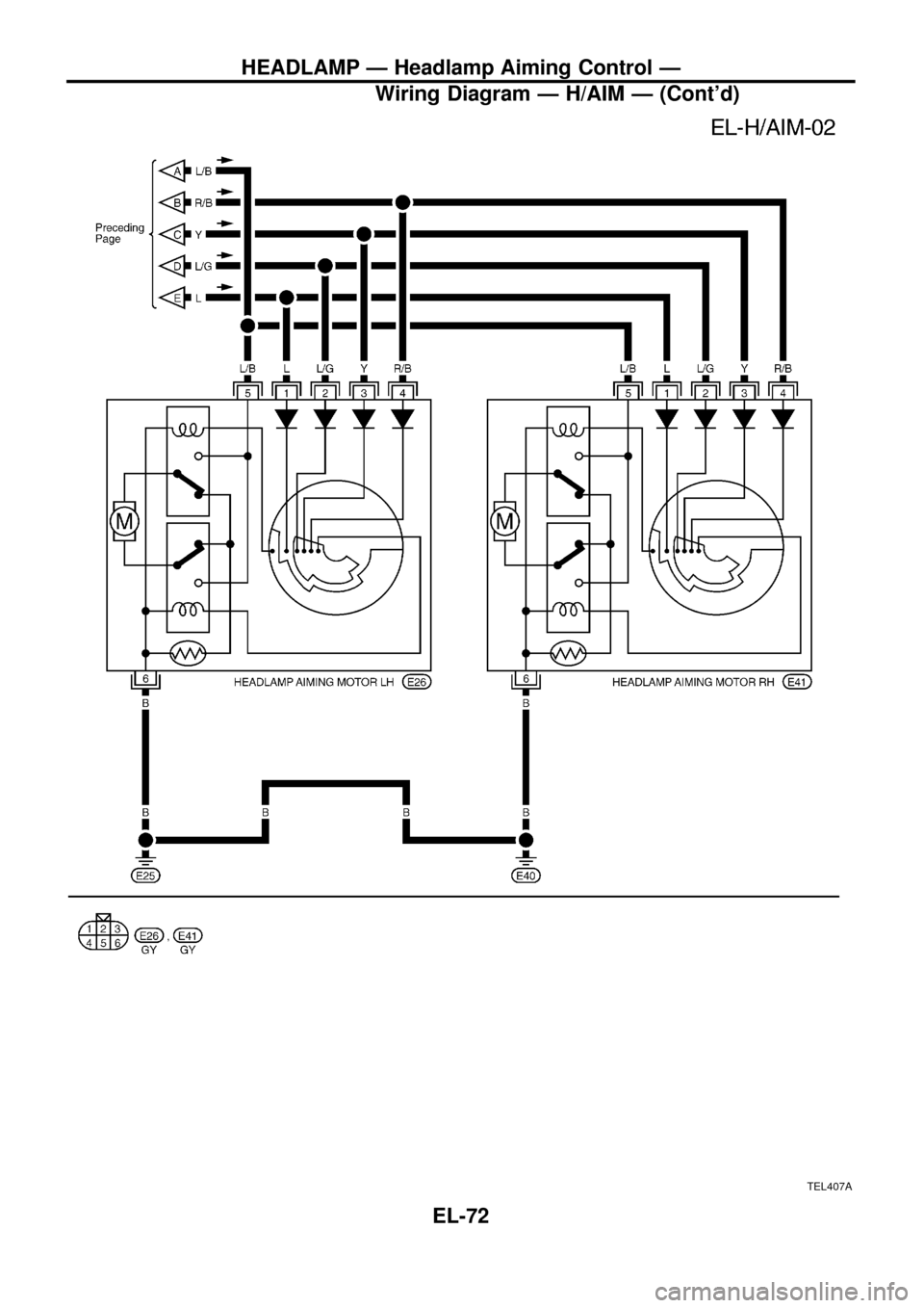
TEL407A
HEADLAMP Ð Headlamp Aiming Control Ð
Wiring Diagram Ð H/AIM Ð (Cont'd)
EL-72
Page 97 of 326
System Description
Front interior room lamp timer is controlled by smart entrance control unit while interior room lamp switch is
in the ``DOOR'' position.
Smart entrance control unit does not control rear interior room lamp.
TIMER OPERATION
Interior room lamp timer keeps interior room lamp illuminated for about 15 seconds when:
+driver's door is unlocked while key is out of ignition key cylinder,
+key is withdrawn from ignition key cylinder while driver's door is closed, and
+driver's door is opened and then closed while ignition switch is not in the ``ON'' position.
The timer is cancelled, and interior room lamp turns off when:
+driver's door is locked, or
+ignition switch is turned ``ON''.
ON-OFF CONTROL
When the front driver side door, front passenger side door, rear LH door, rear RH door or back door is opened,
interior room lamp turns on.
When driver side door is opened and then closed while ignition switch is not in the ON position, interior room
lamp timer operates. (Timer does not operate when doors other than the driver side door is opened and
closed.)
INTERIOR ROOM LAMP Ð With Timer Ð
EL-93
Page 104 of 326
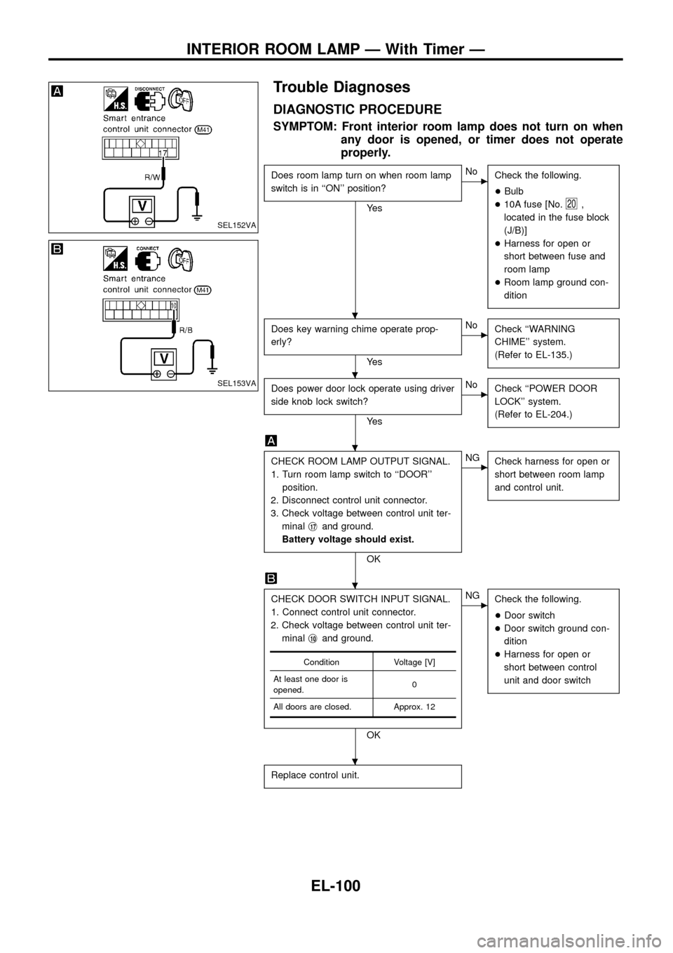
Trouble Diagnoses
DIAGNOSTIC PROCEDURE
SYMPTOM: Front interior room lamp does not turn on when
any door is opened, or timer does not operate
properly.
Does room lamp turn on when room lamp
switch is in ``ON'' position?
Ye s
cNo
Check the following.
+Bulb
+10A fuse [No.
20,
located in the fuse block
(J/B)]
+Harness for open or
short between fuse and
room lamp
+Room lamp ground con-
dition
Does key warning chime operate prop-
erly?
Ye s
cNo
Check ``WARNING
CHIME'' system.
(Refer to EL-135.)
Does power door lock operate using driver
side knob lock switch?
Ye s
cNo
Check ``POWER DOOR
LOCK'' system.
(Refer to EL-204.)
CHECK ROOM LAMP OUTPUT SIGNAL.
1. Turn room lamp switch to ``DOOR''
position.
2. Disconnect control unit connector.
3. Check voltage between control unit ter-
minalj
17and ground.
Battery voltage should exist.
OK
cNG
Check harness for open or
short between room lamp
and control unit.
CHECK DOOR SWITCH INPUT SIGNAL.
1. Connect control unit connector.
2. Check voltage between control unit ter-
minalj
10and ground.
OK
cNG
Check the following.
+Door switch
+Door switch ground con-
dition
+Harness for open or
short between control
unit and door switch
Replace control unit.
Condition Voltage [V]
At least one door is
opened.0
All doors are closed. Approx. 12
SEL152VA
SEL153VA
.
.
.
.
.
INTERIOR ROOM LAMP Ð With Timer Ð
EL-100