diff NISSAN PATROL 1998 Y61 / 5.G Electrical System Workshop Manual
[x] Cancel search | Manufacturer: NISSAN, Model Year: 1998, Model line: PATROL, Model: NISSAN PATROL 1998 Y61 / 5.GPages: 326, PDF Size: 11.36 MB
Page 4 of 326
BULB SPECIFICATIONS............................................314
Headlamp.................................................................314
Exterior Lamp ..........................................................314
Interior Lamp............................................................314
WIRING DIAGRAM CODES (CELL CODES) .............315
WIRING DIAGRAM REFERENCE CHART
ECCS, IGNITION SYSTEM ........................................................................\
................... EC SECTION
ANTI-LOCK BRAKE SYSTEM ........................................................................\
.............. BR SECTION
SRS ``AIR BAG'' ........................................................................\
.................................... RS SECT ION
HEATER AND AIR CONDITIONER ........................................................................\
...... HA SECTION
DIFFERENTIAL CARRIER ........................................................................\
.................... PD SECTION
REAR SUSPENSION ........................................................................\
............................. RA SECTION
FUEL SYSTEM ........................................................................\
....................................... FE SECT ION
Page 44 of 326
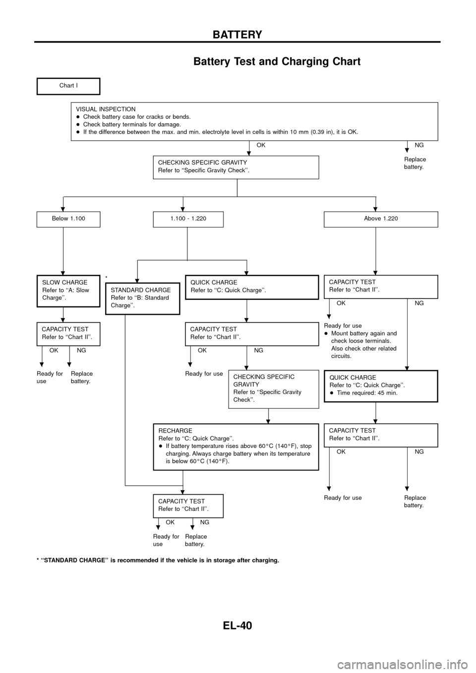
Battery Test and Charging Chart
Chart I
VISUAL INSPECTION
+Check battery case for cracks or bends.
+Check battery terminals for damage.
+If the difference between the max. and min. electrolyte level in cells is within 10 mm (0.39 in), it is OK.
OK NG
CHECKING SPECIFIC GRAVITY
Refer to ``Speci®c Gravity Check''.
Replace
battery.
Below 1.1001.100 - 1.220Above 1.220
SLOW CHARGE
Refer to ``A: Slow
Charge''.*
STANDARD CHARGE
Refer to ``B: Standard
Charge''.QUICK CHARGE
Refer to ``C: Quick Charge''.CAPACITY TEST
Refer to ``Chart II''.
OK NG
CAPACITY TEST
Refer to ``Chart II''.
OK NGCAPACITY TEST
Refer to ``Chart II''.OK NGReady for use
+Mount battery again and
check loose terminals.
Also check other related
circuits.
Ready for
useReplace
battery.Ready for use
CHECKING SPECIFIC
GRAVITY
Refer to ``Speci®c Gravity
Check''.
QUICK CHARGE
Refer to ``C: Quick Charge''.
+Time required: 45 min.
RECHARGE
Refer to ``C: Quick Charge''.
+If battery temperature rises above 60ÉC (140ÉF), stop
charging. Always charge battery when its temperature
is below 60ÉC (140ÉF).CAPACITY TEST
Refer to ``Chart II''.
OK NG
CAPACITY TEST
Refer to ``Chart II''.
OK NGReady for use Replace
battery.
Ready for
useReplace
battery.
* ``STANDARD CHARGE'' is recommended if the vehicle is in storage after charging.
..
...
....
...
.....
..
...
..
BATTERY
EL-40
Page 120 of 326
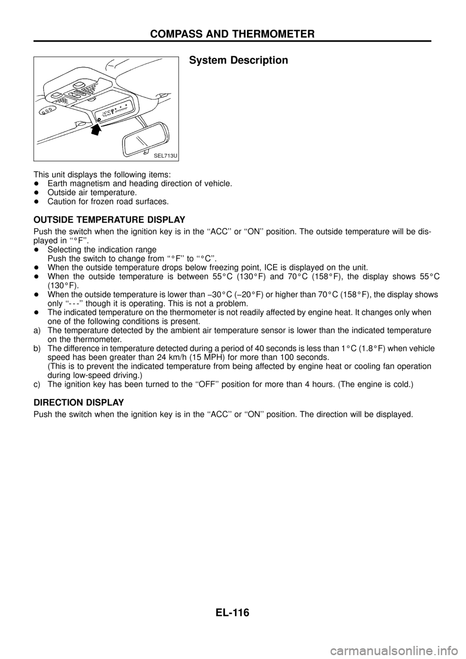
System Description
This unit displays the following items:
+Earth magnetism and heading direction of vehicle.
+Outside air temperature.
+Caution for frozen road surfaces.
OUTSIDE TEMPERATURE DISPLAY
Push the switch when the ignition key is in the ``ACC'' or ``ON'' position. The outside temperature will be dis-
played in ``ÉF''.
+Selecting the indication range
Push the switch to change from ``ÉF'' to ``ÉC''.
+When the outside temperature drops below freezing point, ICE is displayed on the unit.
+When the outside temperature is between 55ÉC (130ÉF) and 70ÉC (158ÉF), the display shows 55ÉC
(130ÉF).
+When the outside temperature is lower than þ30ÉC (þ20ÉF) or higher than 70ÉC (158ÉF), the display shows
only ``- - -'' though it is operating. This is not a problem.
+The indicated temperature on the thermometer is not readily affected by engine heat. It changes only when
one of the following conditions is present.
a) The temperature detected by the ambient air temperature sensor is lower than the indicated temperature
on the thermometer.
b) The difference in temperature detected during a period of 40 seconds is less than 1ÉC (1.8ÉF) when vehicle
speed has been greater than 24 km/h (15 MPH) for more than 100 seconds.
(This is to prevent the indicated temperature from being affected by engine heat or cooling fan operation
during low-speed driving.)
c) The ignition key has been turned to the ``OFF'' position for more than 4 hours. (The engine is cold.)
DIRECTION DISPLAY
Push the switch when the ignition key is in the ``ACC'' or ``ON'' position. The direction will be displayed.
SEL713U
COMPASS AND THERMOMETER
EL-116
Page 123 of 326
a) The temperature detected by the ambient air temperature sensor is lower than the indicated tem-
perature on the thermometer.
b) The difference in temperature detected during a period of 40 seconds is less than 1ÉC (1.8ÉF) when
vehicle speed has been greater than 24 km/h (15 MPH) for more than 100 seconds.
(This is to prevent the indicated temperature from being affected by engine heat or cooling fan
operation during low-speed driving.)
c) The ignition key has been turned to the ``OFF'' position for more than 4 hours. (The engine is cold.)
Calibration Procedure For Compass
The difference between magnetic North and geographical North
can sometimes be great enough to cause false compass readings.
In order for the compass to operate accurately in a particular zone,
it must be calibrated using the following procedure.
1. Determine your location on the worldwide magnetic variation
map on next page. Record your zone number.
2. Turn the ignition switch to ACC or ON position.
3. Push the ``Mode'' switch continuously for ®ve seconds until the
current zone entry number is displayed.
4. Press the ``Mode'' switch repeatedly until the desired zone num-
ber is displayed.
Once the desired zone number is displayed, stop pressing the
``Mode'' switch and the display will show compass direction after a
few seconds.
CORRECTION FUNCTIONS OF COMPASS
The direction display is equipped with automatic correction func-
tion. If the direction is not shown correctly, carry out initial correc-
tion.
INITIAL CORRECTION PROCEDURE FOR COMPASS
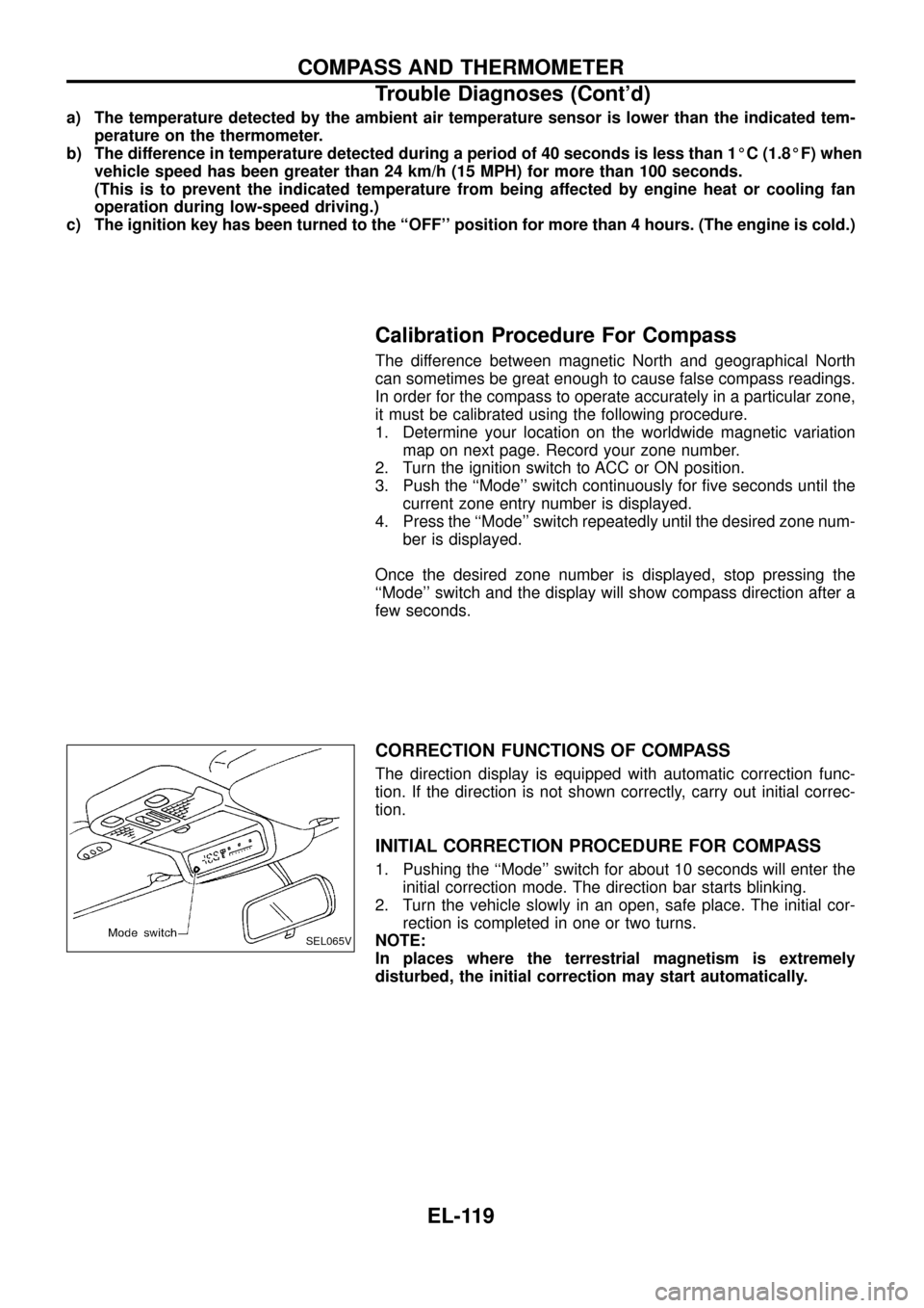
1. Pushing the ``Mode'' switch for about 10 seconds will enter the
initial correction mode. The direction bar starts blinking.
2. Turn the vehicle slowly in an open, safe place. The initial cor-
rection is completed in one or two turns.
NOTE:
In places where the terrestrial magnetism is extremely
disturbed, the initial correction may start automatically.
SEL065V
COMPASS AND THERMOMETER
Trouble Diagnoses (Cont'd)
EL-119
Page 247 of 326
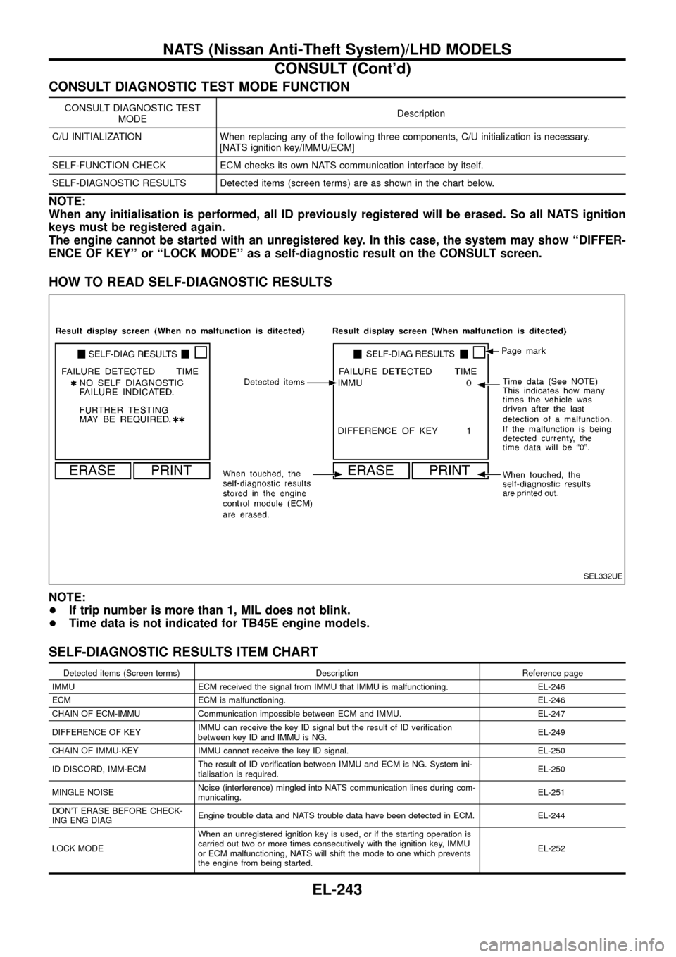
CONSULT DIAGNOSTIC TEST MODE FUNCTION
CONSULT DIAGNOSTIC TEST
MODEDescription
C/U INITIALIZATION When replacing any of the following three components, C/U initialization is necessary.
[NATS ignition key/IMMU/ECM]
SELF-FUNCTION CHECK ECM checks its own NATS communication interface by itself.
SELF-DIAGNOSTIC RESULTS Detected items (screen terms) are as shown in the chart below.
NOTE:
When any initialisation is performed, all ID previously registered will be erased. So all NATS ignition
keys must be registered again.
The engine cannot be started with an unregistered key. In this case, the system may show ``DIFFER-
ENCE OF KEY'' or ``LOCK MODE'' as a self-diagnostic result on the CONSULT screen.
HOW TO READ SELF-DIAGNOSTIC RESULTS
NOTE:
+If trip number is more than 1, MIL does not blink.
+Time data is not indicated for TB45E engine models.
SELF-DIAGNOSTIC RESULTS ITEM CHART
Detected items (Screen terms) Description Reference page
IMMU ECM received the signal from IMMU that IMMU is malfunctioning. EL-246
ECM ECM is malfunctioning. EL-246
CHAIN OF ECM-IMMU Communication impossible between ECM and IMMU. EL-247
DIFFERENCE OF KEYIMMU can receive the key ID signal but the result of ID veri®cation
between key ID and IMMU is NG.EL-249
CHAIN OF IMMU-KEY IMMU cannot receive the key ID signal. EL-250
ID DISCORD, IMM-ECMThe result of ID veri®cation between IMMU and ECM is NG. System ini-
tialisation is required.EL-250
MINGLE NOISENoise (interference) mingled into NATS communication lines during com-
municating.EL-251
DON'T ERASE BEFORE CHECK-
ING ENG DIAGEngine trouble data and NATS trouble data have been detected in ECM. EL-244
LOCK MODEWhen an unregistered ignition key is used, or if the starting operation is
carried out two or more times consecutively with the ignition key, IMMU
or ECM malfunctioning, NATS will shift the mode to one which prevents
the engine from being started.EL-252
SEL332UE
NATS (Nissan Anti-Theft System)/LHD MODELS
CONSULT (Cont'd)
EL-243
Page 249 of 326
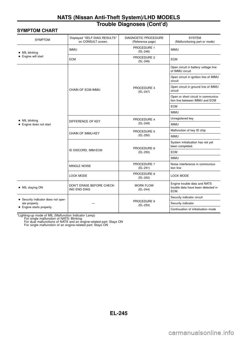
SYMPTOM CHART
SYMPTOMDisplayed ``SELF-DIAG RESULTS''
on CONSULT screen.DIAGNOSTIC PROCEDURE
(Reference page)SYSTEM
(Malfunctioning part or mode)
+MIL blinking
+Engine will startIMMUPROCEDURE 1
(EL-246)IMMU
ECMPROCEDURE 2
(EL-246)ECM
+MIL blinking
+Engine does not startCHAIN OF ECM-IMMUPROCEDURE 3
(EL-247)Open circuit in battery voltage line
of IMMU circuit
Open circuit in ignition line of IMMU
circuit
Open circuit in ground line of IMMU
circuit
Open or short circuit in communica-
tion line between IMMU and ECM
ECM
IMMU
DIFFERENCE OF KEYPROCEDURE 4
(EL-249)Unregistered key
IMMU
CHAIN OF IMMU-KEYPROCEDURE 5
(EL-250)Malfunction of key ID chip
IMMU
ID DISCORD, IMM-ECMPROCEDURE 6
(EL-250)System initialisation has not yet
been completed.
ECM
IMMU
MINGLE NOISEPROCEDURE 7
(EL-251)Noise interference in communica-
tion line
LOCK MODEPROCEDURE 8
(EL-252)LOCK MODE
+MIL staying ONDON'T ERASE BEFORE CHECK-
ING ENG DIAGWORK FLOW
(EL-244)Engine trouble data and NATS
trouble data have been detected in
ECM.
+Security indicator does not oper-
ate properly.
+Engine starts properly.ÐPROCEDURE 9
(EL-253)Security indicator circuit
Security indicator
Continuation of initialisation mode
*Lighting-up mode of MIL (Malfunction Indicator Lamp)
For single malfunction of NATS: Blinking
For dual malfunctions of NATS and an engine-related part: Stays ON
For single malfunction of an engine-related part: Stays ON
NATS (Nissan Anti-Theft System)/LHD MODELS
Trouble Diagnoses (Cont'd)
EL-245
Page 253 of 326
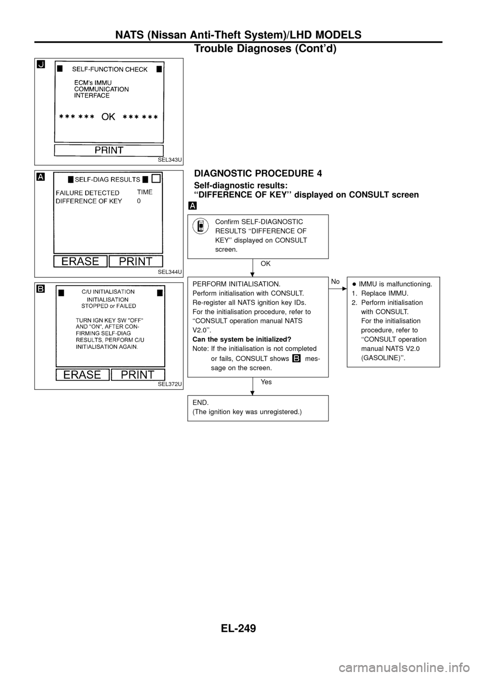
DIAGNOSTIC PROCEDURE 4
Self-diagnostic results:
``DIFFERENCE OF KEY'' displayed on CONSULT screen
Con®rm SELF-DIAGNOSTIC
RESULTS ``DIFFERENCE OF
KEY'' displayed on CONSULT
screen.
OK
PERFORM INITIALISATION.
Perform initialisation with CONSULT.
Re-register all NATS ignition key IDs.
For the initialisation procedure, refer to
``CONSULT operation manual NATS
V2.0''.
Can the system be initialized?
Note: If the initialisation is not completed
or fails, CONSULT shows
mes-
sage on the screen.
Ye s
cNo
+IMMU is malfunctioning.
1. Replace IMMU.
2. Perform initialisation
with CONSULT.
For the initialisation
procedure, refer to
``CONSULT operation
manual NATS V2.0
(GASOLINE)''.
END.
(The ignition key was unregistered.)
SEL343U
SEL344U
SEL372U
.
.
NATS (Nissan Anti-Theft System)/LHD MODELS
Trouble Diagnoses (Cont'd)
EL-249
Page 262 of 326
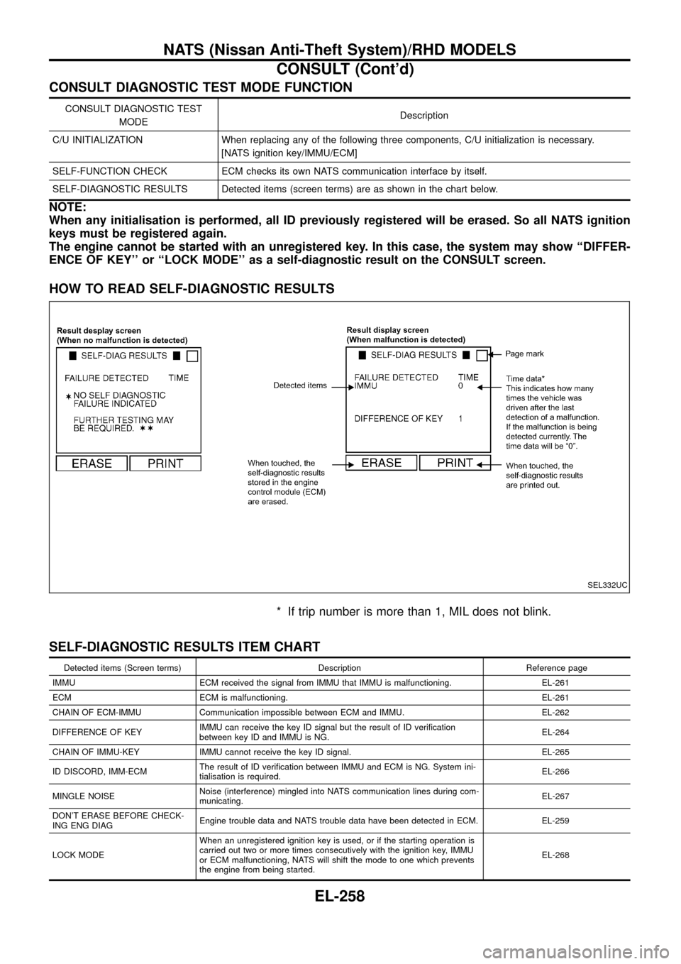
CONSULT DIAGNOSTIC TEST MODE FUNCTION
CONSULT DIAGNOSTIC TEST
MODEDescription
C/U INITIALIZATION When replacing any of the following three components, C/U initialization is necessary.
[NATS ignition key/IMMU/ECM]
SELF-FUNCTION CHECK ECM checks its own NATS communication interface by itself.
SELF-DIAGNOSTIC RESULTS Detected items (screen terms) are as shown in the chart below.
NOTE:
When any initialisation is performed, all ID previously registered will be erased. So all NATS ignition
keys must be registered again.
The engine cannot be started with an unregistered key. In this case, the system may show ``DIFFER-
ENCE OF KEY'' or ``LOCK MODE'' as a self-diagnostic result on the CONSULT screen.
HOW TO READ SELF-DIAGNOSTIC RESULTS
* If trip number is more than 1, MIL does not blink.
SELF-DIAGNOSTIC RESULTS ITEM CHART
Detected items (Screen terms) Description Reference page
IMMU ECM received the signal from IMMU that IMMU is malfunctioning. EL-261
ECM ECM is malfunctioning. EL-261
CHAIN OF ECM-IMMU Communication impossible between ECM and IMMU. EL-262
DIFFERENCE OF KEYIMMU can receive the key ID signal but the result of ID veri®cation
between key ID and IMMU is NG.EL-264
CHAIN OF IMMU-KEY IMMU cannot receive the key ID signal. EL-265
ID DISCORD, IMM-ECMThe result of ID veri®cation between IMMU and ECM is NG. System ini-
tialisation is required.EL-266
MINGLE NOISENoise (interference) mingled into NATS communication lines during com-
municating.EL-267
DON'T ERASE BEFORE CHECK-
ING ENG DIAGEngine trouble data and NATS trouble data have been detected in ECM. EL-259
LOCK MODEWhen an unregistered ignition key is used, or if the starting operation is
carried out two or more times consecutively with the ignition key, IMMU
or ECM malfunctioning, NATS will shift the mode to one which prevents
the engine from being started.EL-268
SEL332UC
NATS (Nissan Anti-Theft System)/RHD MODELS
CONSULT (Cont'd)
EL-258
Page 264 of 326
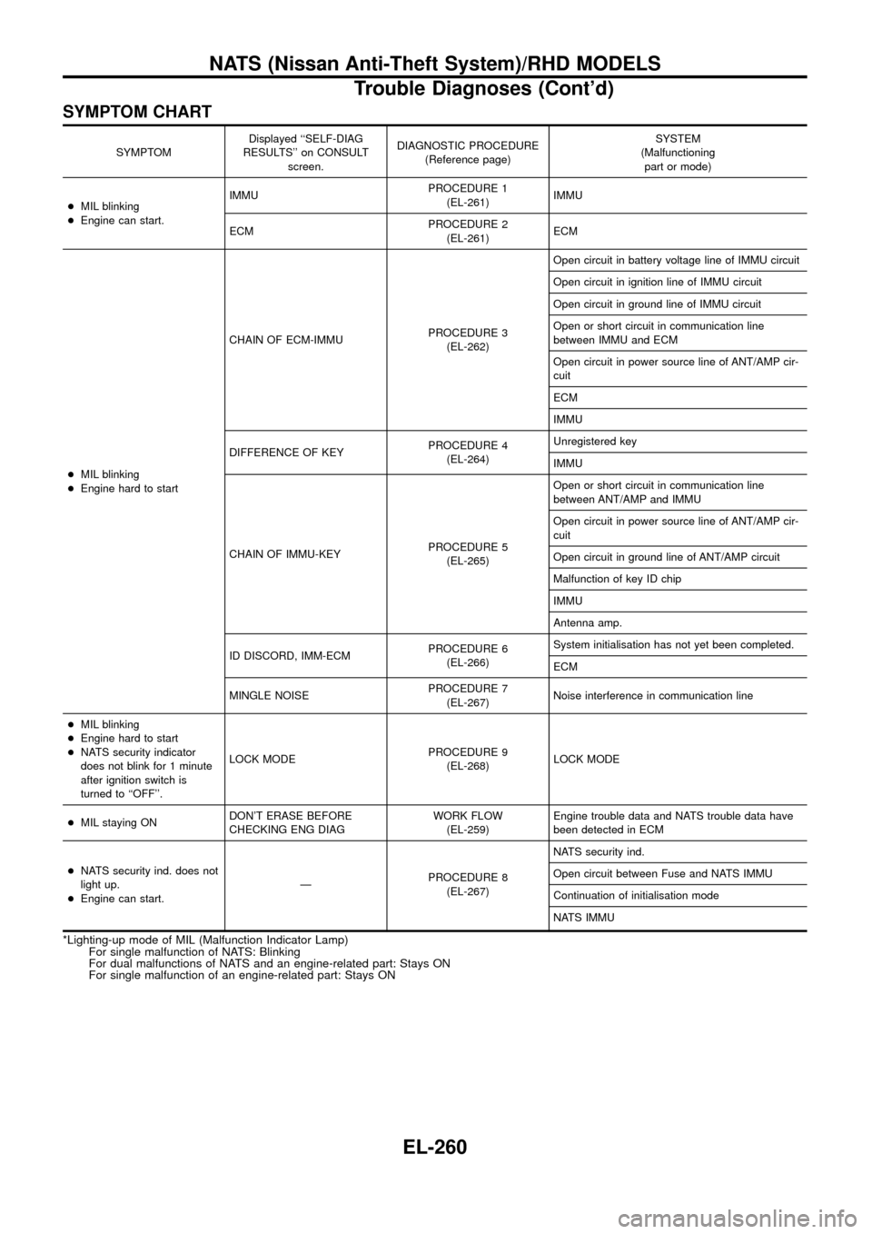
SYMPTOM CHART
SYMPTOMDisplayed ``SELF-DIAG
RESULTS'' on CONSULT
screen.DIAGNOSTIC PROCEDURE
(Reference page)SYSTEM
(Malfunctioning
part or mode)
+MIL blinking
+Engine can start.IMMUPROCEDURE 1
(EL-261)IMMU
ECMPROCEDURE 2
(EL-261)ECM
+MIL blinking
+Engine hard to startCHAIN OF ECM-IMMUPROCEDURE 3
(EL-262)Open circuit in battery voltage line of IMMU circuit
Open circuit in ignition line of IMMU circuit
Open circuit in ground line of IMMU circuit
Open or short circuit in communication line
between IMMU and ECM
Open circuit in power source line of ANT/AMP cir-
cuit
ECM
IMMU
DIFFERENCE OF KEYPROCEDURE 4
(EL-264)Unregistered key
IMMU
CHAIN OF IMMU-KEYPROCEDURE 5
(EL-265)Open or short circuit in communication line
between ANT/AMP and IMMU
Open circuit in power source line of ANT/AMP cir-
cuit
Open circuit in ground line of ANT/AMP circuit
Malfunction of key ID chip
IMMU
Antenna amp.
ID DISCORD, IMM-ECMPROCEDURE 6
(EL-266)System initialisation has not yet been completed.
ECM
MINGLE NOISEPROCEDURE 7
(EL-267)Noise interference in communication line
+MIL blinking
+Engine hard to start
+NATS security indicator
does not blink for 1 minute
after ignition switch is
turned to ``OFF''.LOCK MODEPROCEDURE 9
(EL-268)LOCK MODE
+MIL staying ONDON'T ERASE BEFORE
CHECKING ENG DIAGWORK FLOW
(EL-259)Engine trouble data and NATS trouble data have
been detected in ECM
+NATS security ind. does not
light up.
+Engine can start.ÐPROCEDURE 8
(EL-267)NATS security ind.
Open circuit between Fuse and NATS IMMU
Continuation of initialisation mode
NATS IMMU
*Lighting-up mode of MIL (Malfunction Indicator Lamp)
For single malfunction of NATS: Blinking
For dual malfunctions of NATS and an engine-related part: Stays ON
For single malfunction of an engine-related part: Stays ON
NATS (Nissan Anti-Theft System)/RHD MODELS
Trouble Diagnoses (Cont'd)
EL-260
Page 268 of 326
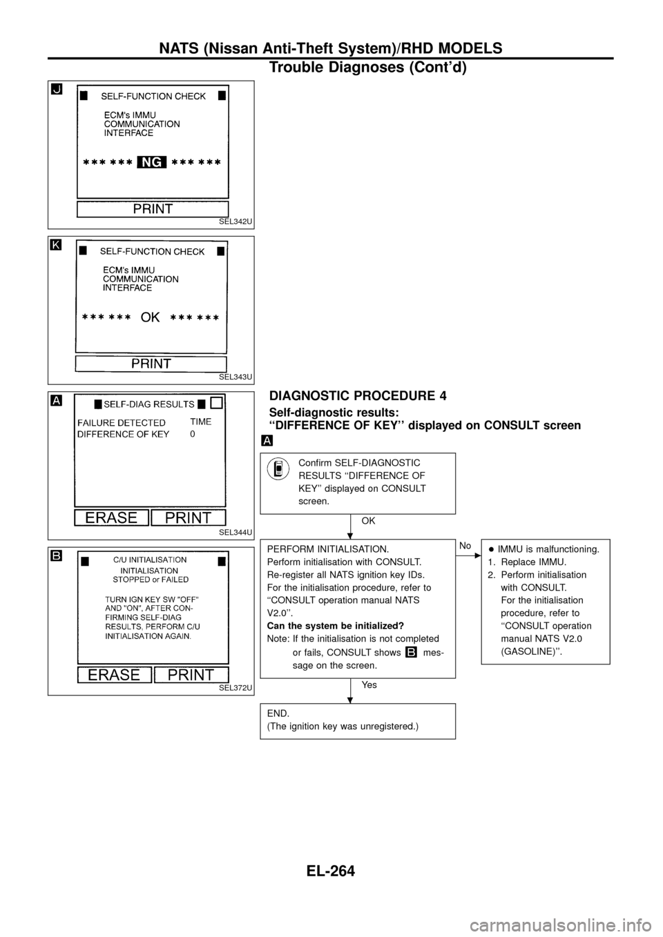
DIAGNOSTIC PROCEDURE 4
Self-diagnostic results:
``DIFFERENCE OF KEY'' displayed on CONSULT screen
Con®rm SELF-DIAGNOSTIC
RESULTS ``DIFFERENCE OF
KEY'' displayed on CONSULT
screen.
OK
PERFORM INITIALISATION.
Perform initialisation with CONSULT.
Re-register all NATS ignition key IDs.
For the initialisation procedure, refer to
``CONSULT operation manual NATS
V2.0''.
Can the system be initialized?
Note: If the initialisation is not completed
or fails, CONSULT shows
mes-
sage on the screen.
Ye s
cNo
+IMMU is malfunctioning.
1. Replace IMMU.
2. Perform initialisation
with CONSULT.
For the initialisation
procedure, refer to
``CONSULT operation
manual NATS V2.0
(GASOLINE)''.
END.
(The ignition key was unregistered.)
SEL342U
SEL343U
SEL344U
SEL372U
.
.
NATS (Nissan Anti-Theft System)/RHD MODELS
Trouble Diagnoses (Cont'd)
EL-264