coolant NISSAN PATROL 1998 Y61 / 5.G Engine Control User Guide
[x] Cancel search | Manufacturer: NISSAN, Model Year: 1998, Model line: PATROL, Model: NISSAN PATROL 1998 Y61 / 5.GPages: 192, PDF Size: 4.28 MB
Page 50 of 192
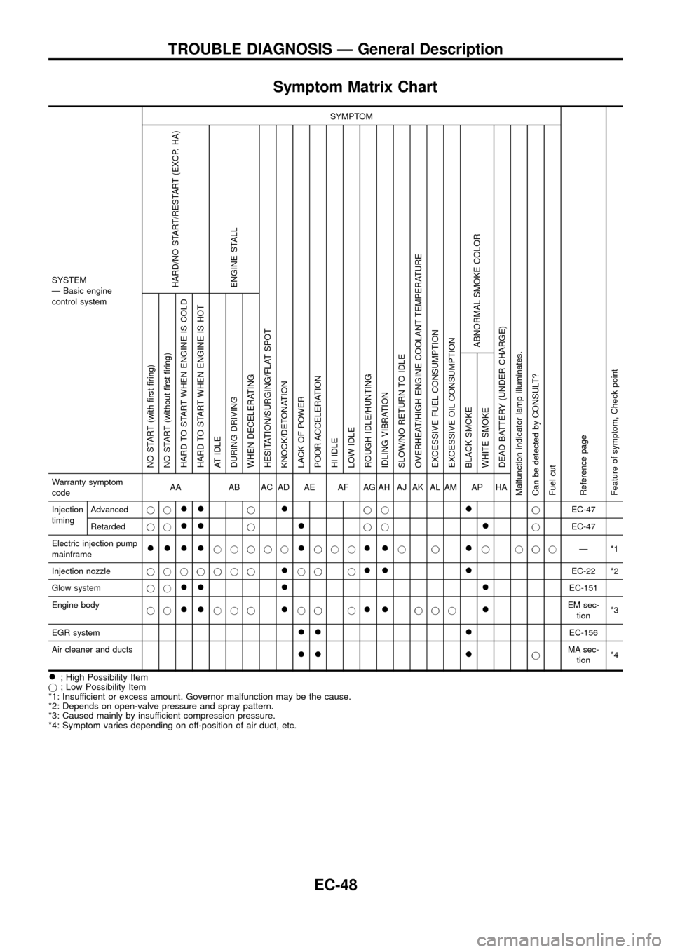
Symptom Matrix Chart
SYSTEM
Ð Basic engine
control systemSYMPTOM
Reference page
Feature of symptom, Check pointHARD/NO START/RESTART (EXCP. HA)
ENGINE STALL
HESITATION/SURGING/FLAT SPOT
KNOCK/DETONATION
LACK OF POWER
POOR ACCELERATION
HI IDLE
LOW IDLE
ROUGH IDLE/HUNTING
IDLING VIBRATION
SLOW/NO RETURN TO IDLE
OVERHEAT/HIGH ENGINE COOLANT TEMPERATURE
EXCESSIVE FUEL CONSUMPTION
EXCESSIVE OIL CONSUMPTION
ABNORMAL SMOKE COLOR
DEAD BATTERY (UNDER CHARGE)
Malfunction indicator lamp illuminates.
Can be detected by CONSULT?
Fuel cutNO START (with ®rst ®ring)
NO START (without ®rst ®ring)
HARD TO START WHEN ENGINE IS COLD
HARD TO START WHEN ENGINE IS HOT
AT IDLE
DURING DRIVING
WHEN DECELERATING
BLACK SMOKE
WHITE SMOKEWarranty symptom
codeAA AB AC AD AE AF AG AH AJ AK AL AM AP HA
Injection
timingAdvancedjj
++j+jj+jEC-47
Retardedjj
++j+jj+jEC-47
Electric injection pump
mainframe
++++jjjjj+jjj++jj+j jjjÐ*1
Injection nozzlejjjjjjj
+jj j++ +EC-22 *2
Glow systemjj
++ + +EC-151
Engine body
jj
++jjj+jj j++jjj+EM sec-
tion*3
EGR system
++ +EC-156
Air cleaner and ducts
++ +jMA sec-
tion*4
+; High Possibility Item
j; Low Possibility Item
*1: Insufficient or excess amount. Governor malfunction may be the cause.
*2: Depends on open-valve pressure and spray pattern.
*3: Caused mainly by insufficient compression pressure.
*4: Symptom varies depending on off-position of air duct, etc.
TROUBLE DIAGNOSIS Ð General Description
EC-48
Page 51 of 192
SYSTEM
Ð ECCS systemMalfunction
SYMPTOM
Reference
page Feature of symptom
Check point
HARD/NO START/
RESTART (EXCP. HA) ENGINE STALL HESITATION/SURGING/FLAT SPOT KNOCK/DETONATION
LACK OF POWER
POOR ACCELERATION
HI IDLE
LOW IDLE
ROUGH IDLE/HUNTING
IDLING VIBRATION
SLOW/NO RETURN TO IDLE
OVERHEAT/HIGH ENGINE COOLANT TEMPERATURE
EXCESSIVE FUEL CONSUMPTION
EXCESSIVE OIL CONSUMPTION ABNORMAL SMOKE COLOR
DEAD BATTERY (UNDER CHARGE) Malfunction indicator lamp illuminates.
Can be detected by CONSULT?
Fuel cut
NO START (with ®rst ®ring) NO START (without ®rst ®ring)
HARD TO START WHEN ENGINE IS COLD
HARD TO START WHEN ENGINE IS HOT
AT IDLE
DURING DRIVING
WHEN DECELERATINGBLACK SMOKE WHITE SMOKE
Warranty symptom code AA AB AC AD AE AF AG AH AJ AK AL AM AP HAECCS
Camshaft position sensor (PUMP) cir-
cuitopen, shortjj
EC-69Tachometer malfunction
noisejjjj jj
Mass air ¯ow sensor circuitopen, ground shortjjj j
EC-74
shortjjj
Engine coolant temperature sensor
circuitopen, shortjjj jjj jjEC-79Compensation according to
engine coolant temperature does
not function.
Vehicle speed sensor circuit open, shortjjEC-83
Control sleeve position sensor circuit open, shortjjjjjjEC-87
Adjustment resistor circuit open, shortj j jjjj j jEC-92
Electric governor circuitopen, ground shortj jjjjjj
EC-96
shortjj
Injection timing control valve circuitopen, shortjjj
EC-101Injection timing cannot be con-
trolled.
ground shortjj
Accelerator switch (FC) circuitopen, shortjjj
EC-106
ground shortjj
Charge air temperature sensor circuit open, shortjEC-122
Needle lift sensor circuit open, shortjjjEC-126
Fuel cut solenoid valve circuitopen, ground shortj jjjj
EC-130
shortjjjEngine runs on after turning igni-
tion switch OFF.
Fuel temperature sensor circuit open, shortjj jj jj j jj jEC-135Compensation for amount of fuel
injected according to fuel tem-
perature does not function.
Accelerator position sensor circuit open, shortjjj jjEC-139
Crankshaft position sensor (TDC) cir-
cuitopen, shortjj jj
EC-144
noisejjjjj
TROUBLE DIAGNOSIS Ð General Description
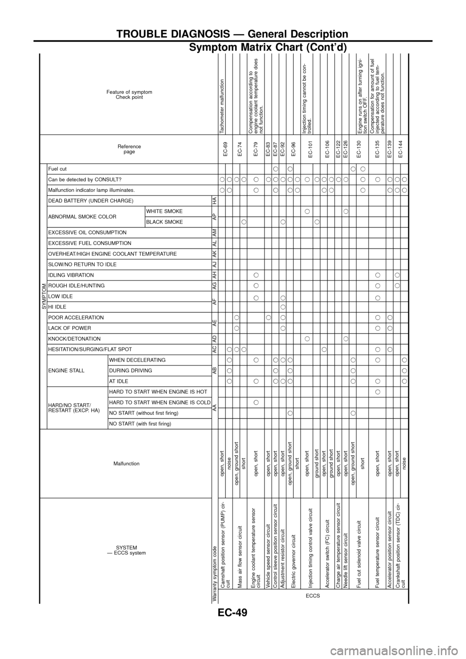
Symptom Matrix Chart (Cont'd)
EC-49
Page 52 of 192
SYSTEM
Ð ECCS systemMalfunction
SYMPTOM
Reference page Feature of symptom
Check point
HARD/NO START/
RESTART (EXCP. HA) ENGINE STALL HESITATION/SURGING/FLAT SPOT KNOCK/DETONATION
LACK OF POWER
POOR ACCELERATION
HI IDLE
LOW IDLE
ROUGH IDLE/HUNTING
IDLING VIBRATION
SLOW/NO RETURN TO IDLE
OVERHEAT/HIGH ENGINE COOLANT TEMPERATURE
EXCESSIVE FUEL CONSUMPTION
EXCESSIVE OIL CONSUMPTION ABNORMAL SMOKE COLOR
DEAD BATTERY (UNDER CHARGE) Malfunction indicator lamp illuminates.
Can be detected by CONSULT?
Fuel cut
NO START (with ®rst ®ring) NO START (without ®rst ®ring)
HARD TO START WHEN ENGINE IS COLD
HARD TO START WHEN ENGINE IS HOT
AT IDLE
DURING DRIVING
WHEN DECELERATINGBLACK SMOKE WHITE SMOKE
Warranty symptom code AA AB AC AD AE AF AG AH AJ AK AL AM AP HAECCS
Start signal circuit open, shortjjEC-163 Start control does not function.
Neutral position switch circuitopen, shortjjj
EC-170
ground shortjj
Accelerator position switch (Idle) cir-
cuitopen, ground shortjj j
EC-165
shortjjj jjAccelerator position sensor NG
signal is output.
Accelerator position switch (Full) cir-
cuitopen, shortjjj jjEC-165
Ignition switch circuitopenj jjj
EC-63
shortEngine does not stop.
Power supply for ECM circuitopenjjj
EC-63
shortjj
Throttle control solenoid valve circuitopen, short
EC-156Does not operate.
ground shortjj jDoes not stop operating.
EGRC-solenoid valve A, B circuitopen, short
EC-156
ground shortjDoes not stop operating.
Glow relay circuitopenjjjjj
EC-151Glow lamp does not turn on.
shortGlow lamp does not turn off.
ECCS relay (Self-shutoff) circuitopenjjjj
EC-63
shortjjGround short makes engine
unable to stop.
ECM, Connector circuit open, shortjjjjjjjjjjjjj jjjjjjjjjjjjEC-111
Air conditioner relay circuitopen
EC-187Air conditioner does not operate.
shortAir conditioner does not stop
operating.
Air conditioner switch circuitopen, ground short
EC-187Air conditioner does not stop
operating.
shortAir conditioner does not work.
TROUBLE DIAGNOSIS Ð General Description
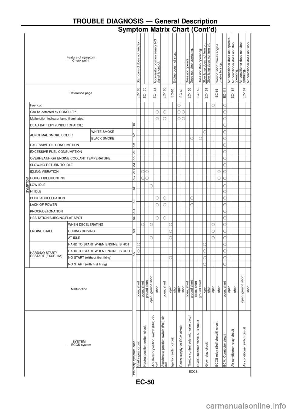
Symptom Matrix Chart (Cont'd)
EC-50
Page 58 of 192
TER-
MINAL
NO.WIRE
COLORITEM CONDITIONDATA
(DC Voltage and Pulse
Signal)
8 G/ORCharge air cooler fan
relayEngine is running.
Charge air cooler fan is not operating.BATTERY VOLTAGE
(11 - 14V)
Engine is running.
Charge air cooler fan is operating.0-1V
10 P Fuel temperature sensor Engine is running.
Approximately 0 - 4.8V
Output voltage varies with
fuel temperature.
14 L Cooling fan relayEngine is running.
Cooling fan is not operating.BATTERY VOLTAGE
(11 - 14V)
Engine is running.
Cooling fan is operating.0-1V
15 Y/L Air conditioner relayEngine is running.
Air conditioner switch is ``OFF''.BATTERY VOLTAGE
(11 - 14V)
Engine is running.
Both air conditioner switch and blower fan
switch are ``ON''.
(Compressor is operating.)0-1V
16 L/W Glow lampIgnition switch ``ON''
Glow lamp is ``ON''.0 - 1.5V
Ignition switch ``ON''
Glow lamp is ``OFF''.BATTERY VOLTAGE
(11 - 14V)
18 G Malfunction indicator lampIgnition switch ``ON''
0 - 1.5V
Engine is running.
Idle speedBATTERY VOLTAGE
(11 - 14V)
19 LG/REngine coolant tempera-
ture sensorEngine is running.
Approximately 0 - 4.8V
Output voltage varies with
engine coolant tempera-
ture.
20 R/W Start signalIgnition switch ``ON''
Approximately 0V
Ignition switch ``START''
BATTERY VOLTAGE
(11 - 14V)
21 LG/B Air conditioner switchEngine is running.
Air conditioner switch is ``OFF''.BATTERY VOLTAGE
(11 - 14V)
Engine is running.
Both air conditioner switch and blower fan
switch are ``ON''.
(Compressor is operating.)Approximately 0V
TROUBLE DIAGNOSIS Ð General Description
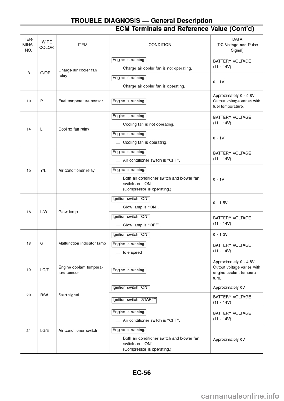
ECM Terminals and Reference Value (Cont'd)
EC-56
Page 81 of 192
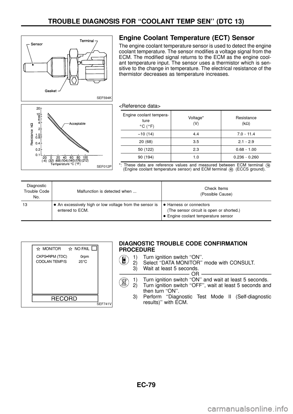
Engine Coolant Temperature (ECT) Sensor
The engine coolant temperature sensor is used to detect the engine
coolant temperature. The sensor modi®es a voltage signal from the
ECM. The modi®ed signal returns to the ECM as the engine cool-
ant temperature input. The sensor uses a thermistor which is sen-
sitive to the change in temperature. The electrical resistance of the
thermistor decreases as temperature increases.
Engine coolant tempera-
ture
ÉC (ÉF)Voltage*
(V)Resistance
(kW)
þ10 (14) 4.4 7.0 - 11.4
20 (68) 3.5 2.1 - 2.9
50 (122) 2.3 0.68 - 1.00
90 (194) 1.0 0.236 - 0.260
*: These data are reference values and measured between ECM terminal
V19(Engine coolant temperature sensor) and ECM terminalV43(ECCS ground).
Diagnostic
Trouble Code
No.Malfunction is detected when ...Check Items
(Possible Cause)
13+An excessively high or low voltage from the sensor is
entered to ECM.+Harness or connectors
(The sensor circuit is open or shorted.)
+Engine coolant temperature sensor
DIAGNOSTIC TROUBLE CODE CONFIRMATION
PROCEDURE
1) Turn ignition switch ``ON''.
2) Select ``DATA MONITOR'' mode with CONSULT.
3) Wait at least 5 seconds.
-------------------------------------------------------------------------------------------------------------------------------------------------------------------------------------------------------------------------------------------------------OR-------------------------------------------------------------------------------------------------------------------------------------------------------------------------------------------------------------------------------------------------------
1) Turn ignition switch ``ON'' and wait at least 5 seconds.
2) Turn ignition switch ``OFF'', wait at least 5 seconds and
then turn ``ON''.
3) Perform ``Diagnostic Test Mode II (Self-diagnostic
results)'' with ECM.
SEF594K
SEF012P
SEF741V
TROUBLE DIAGNOSIS FOR ``COOLANT TEMP SEN'' (DTC 13)
EC-79
Page 82 of 192

TEC425
TROUBLE DIAGNOSIS FOR ``COOLANT TEMP SEN'' (DTC 13)
Engine Coolant Temperature (ECT) Sensor
(Cont'd)
EC-80
Page 83 of 192

DIAGNOSTIC PROCEDURE
INSPECTION START
CHECK POWER SUPPLY.
1. Turn ignition switch ``OFF''.
2. Disconnect engine coolant temperature
sensor harness connector.
3. Turn ignition switch ``ON''.
4. Check voltage between terminal
V2and ground with CONSULT or tester.
Voltage:
Approximately 5V
OK
cNG
Check the following.
+Harness connectors
E202,E69+Harness connectorsE127,M21+Harness connectorsM51,F6+Harness for open or
short between ECM and
engine coolant tempera-
ture sensor
If NG, repair harness or
connectors.
CHECK GROUND CIRCUIT.
1. Turn ignition switch ``OFF''.
2. Check harness continuity between ter-
minal
V1and engine ground.
Continuity should exist.
If OK, check harness for short to
ground and short to power.
OK
cNG
Check the following.
+Harness connectors
E202,E69+Harness connectorsE127,M21+Harness connectorsM50,F5+Harness connectorsF6,M51+Harness connectorsM88,E106+Harness for open or
short between ECM and
engine coolant tempera-
ture sensor
+Harness for open or
short between TCM and
engine coolant tempera-
ture sensor
If NG, repair open circuit or
short to ground or short to
power in harness or con-
nectors.
CHECK COMPONENT
(Engine coolant temperature sensor).
Refer to ``COMPONENT INSPECTION''
on next page.
OK
cNG
Replace engine coolant
temperature sensor.
Disconnect and reconnect harness con-
nectors in the circuit. Then retest.
Trouble is not ®xed.
Check ECM pin terminals for damage and
check the connection of ECM harness
connector. Reconnect ECM harness con-
nector and retest.
INSPECTION END
SEF678V
SEF541P
SEF542P
.
.
.
.
.
.
TROUBLE DIAGNOSIS FOR ``COOLANT TEMP SEN'' (DTC 13)
Engine Coolant Temperature (ECT) Sensor
(Cont'd)
EC-81
Page 84 of 192
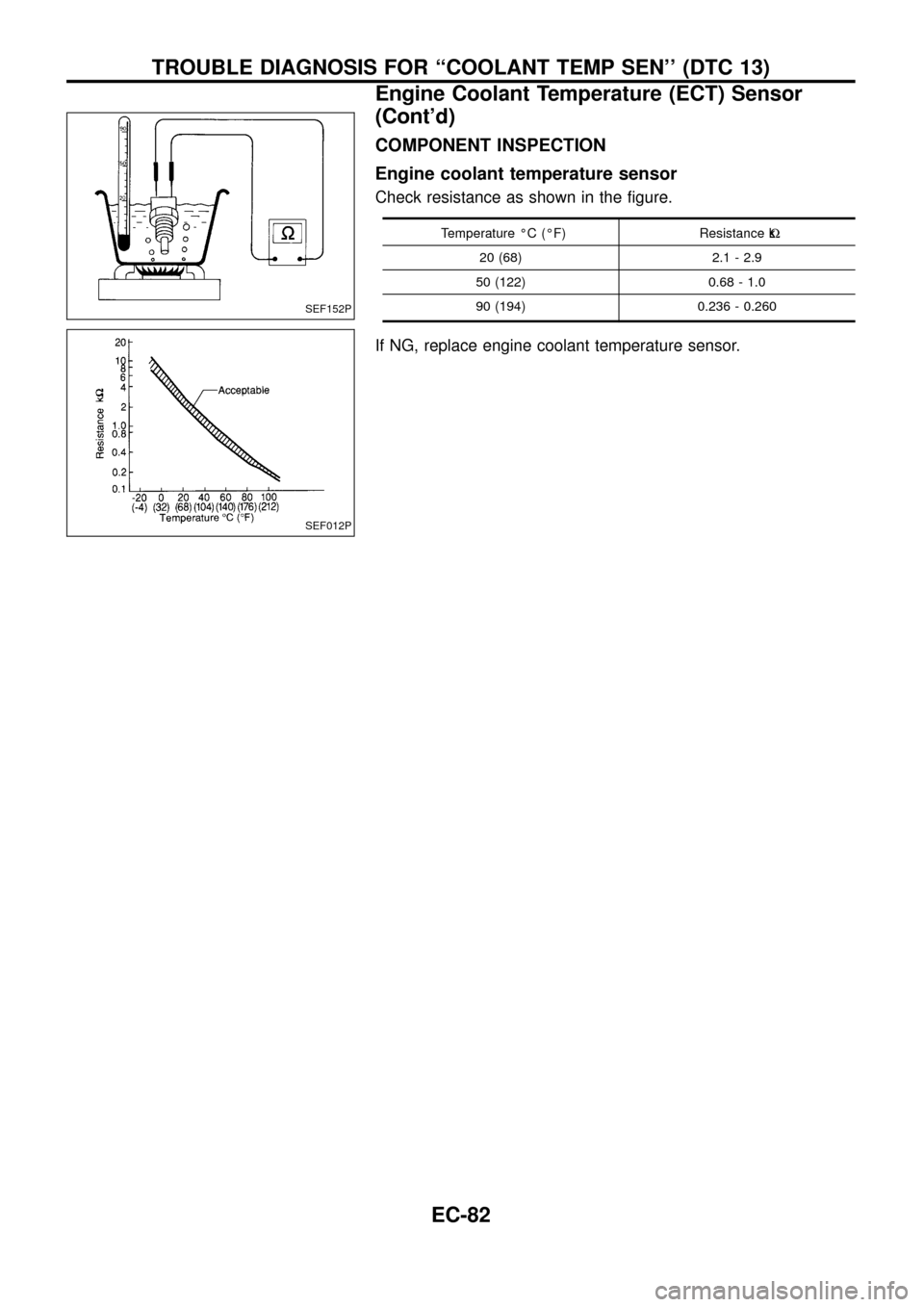
COMPONENT INSPECTION
Engine coolant temperature sensor
Check resistance as shown in the ®gure.
Temperature ÉC (ÉF) Resistance kW
20 (68) 2.1 - 2.9
50 (122) 0.68 - 1.0
90 (194) 0.236 - 0.260
If NG, replace engine coolant temperature sensor.
SEF152P
SEF012P
TROUBLE DIAGNOSIS FOR ``COOLANT TEMP SEN'' (DTC 13)
Engine Coolant Temperature (ECT) Sensor
(Cont'd)
EC-82
Page 115 of 192
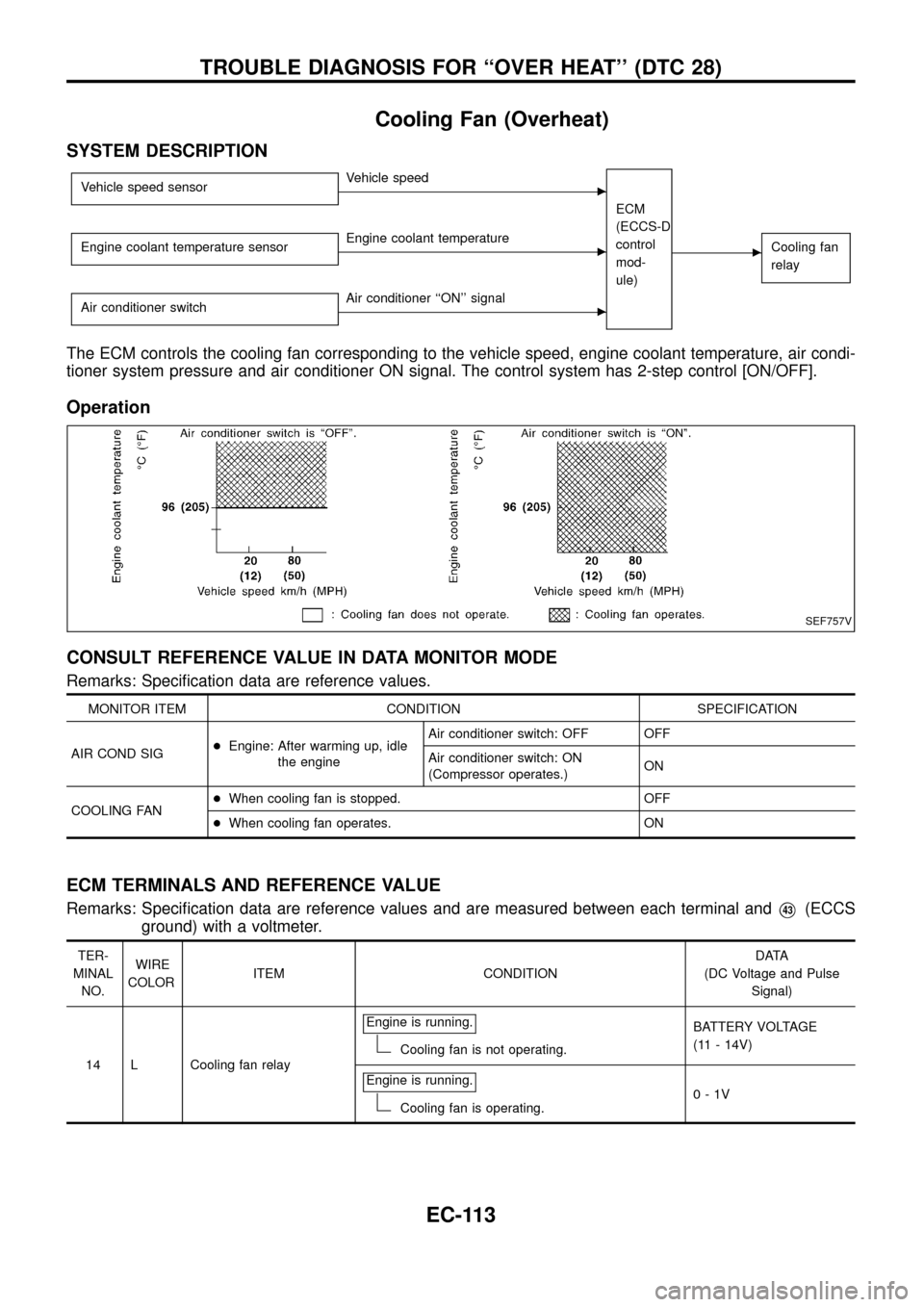
Cooling Fan (Overheat)
SYSTEM DESCRIPTION
Vehicle speed sensorcVehicle speed
ECM
(ECCS-D
control
mod-
ule)
cCooling fan
relayEngine coolant temperature sensorcEngine coolant temperature
Air conditioner switch
cAir conditioner ``ON'' signal
The ECM controls the cooling fan corresponding to the vehicle speed, engine coolant temperature, air condi-
tioner system pressure and air conditioner ON signal. The control system has 2-step control [ON/OFF].
Operation
CONSULT REFERENCE VALUE IN DATA MONITOR MODE
Remarks: Speci®cation data are reference values.
MONITOR ITEM CONDITION SPECIFICATION
AIR COND SIG+Engine: After warming up, idle
the engineAir conditioner switch: OFF OFF
Air conditioner switch: ON
(Compressor operates.)ON
COOLING FAN+When cooling fan is stopped. OFF
+When cooling fan operates. ON
ECM TERMINALS AND REFERENCE VALUE
Remarks: Speci®cation data are reference values and are measured between each terminal andV43(ECCS
ground) with a voltmeter.
TER-
MINAL
NO.WIRE
COLORITEM CONDITIONDATA
(DC Voltage and Pulse
Signal)
14 L Cooling fan relayEngine is running.
Cooling fan is not operating.BATTERY VOLTAGE
(11 - 14V)
Engine is running.
Cooling fan is operating.0-1V
SEF757V
TROUBLE DIAGNOSIS FOR ``OVER HEAT'' (DTC 28)
EC-113
Page 116 of 192
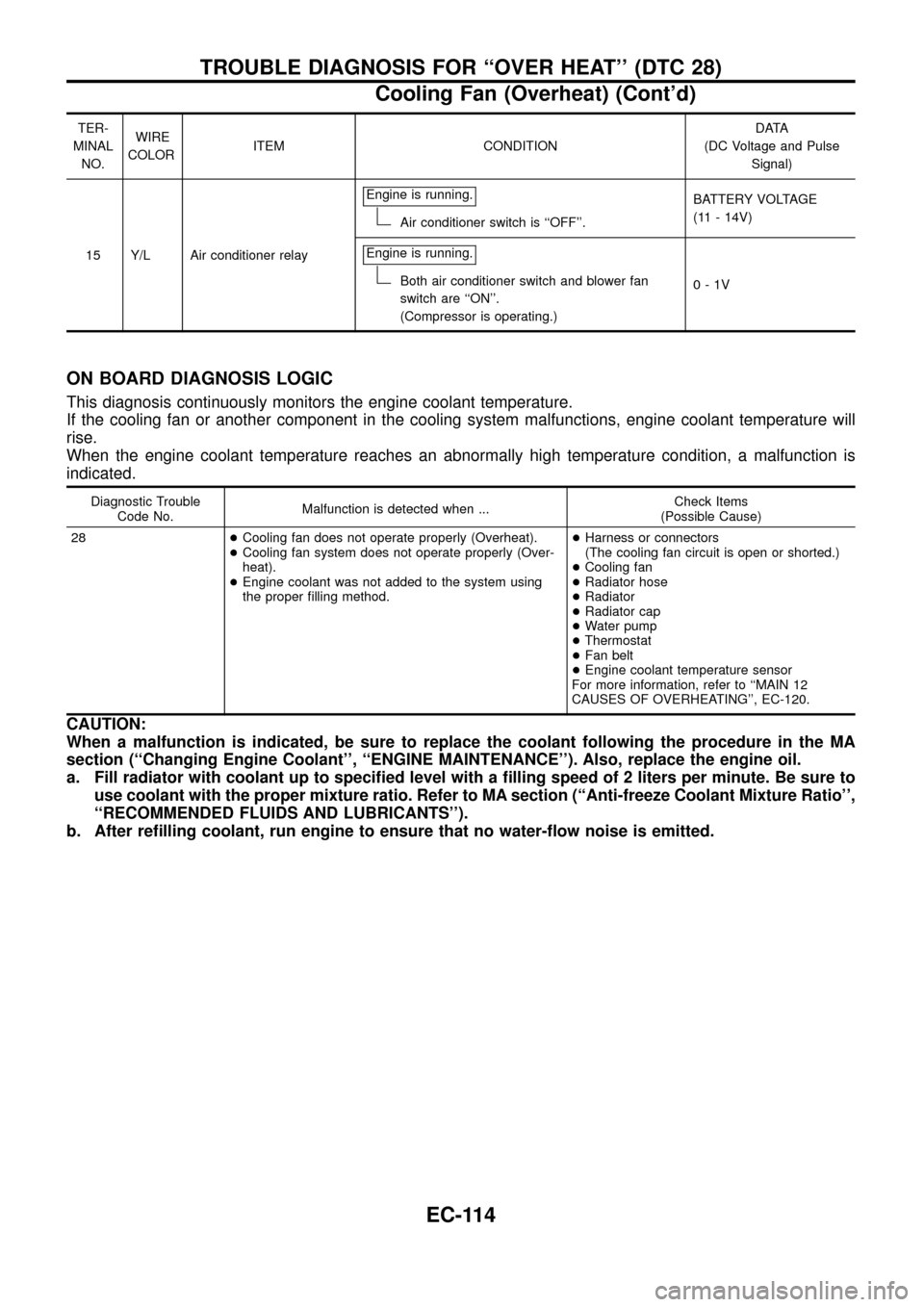
TER-
MINAL
NO.WIRE
COLORITEM CONDITIONDATA
(DC Voltage and Pulse
Signal)
15 Y/L Air conditioner relayEngine is running.
Air conditioner switch is ``OFF''.BATTERY VOLTAGE
(11 - 14V)
Engine is running.
Both air conditioner switch and blower fan
switch are ``ON''.
(Compressor is operating.)0-1V
ON BOARD DIAGNOSIS LOGIC
This diagnosis continuously monitors the engine coolant temperature.
If the cooling fan or another component in the cooling system malfunctions, engine coolant temperature will
rise.
When the engine coolant temperature reaches an abnormally high temperature condition, a malfunction is
indicated.
Diagnostic Trouble
Code No.Malfunction is detected when ...Check Items
(Possible Cause)
28+Cooling fan does not operate properly (Overheat).
+Cooling fan system does not operate properly (Over-
heat).
+Engine coolant was not added to the system using
the proper ®lling method.+Harness or connectors
(The cooling fan circuit is open or shorted.)
+Cooling fan
+Radiator hose
+Radiator
+Radiator cap
+Water pump
+Thermostat
+Fan belt
+Engine coolant temperature sensor
For more information, refer to ``MAIN 12
CAUSES OF OVERHEATING'', EC-120.
CAUTION:
When a malfunction is indicated, be sure to replace the coolant following the procedure in the MA
section (``Changing Engine Coolant'', ``ENGINE MAINTENANCE''). Also, replace the engine oil.
a. Fill radiator with coolant up to speci®ed level with a ®lling speed of 2 liters per minute. Be sure to
use coolant with the proper mixture ratio. Refer to MA section (``Anti-freeze Coolant Mixture Ratio'',
``RECOMMENDED FLUIDS AND LUBRICANTS'').
b. After re®lling coolant, run engine to ensure that no water-¯ow noise is emitted.
TROUBLE DIAGNOSIS FOR ``OVER HEAT'' (DTC 28)
Cooling Fan (Overheat) (Cont'd)
EC-114