NISSAN PATROL 2000 Electronic Repair Manual
PATROL 2000
NISSAN
NISSAN
https://www.carmanualsonline.info/img/5/57367/w960_57367-0.png
NISSAN PATROL 2000 Electronic Repair Manual
Trending: refrigerant type, SOLENOID, wheel bolts, engine oil capacity, overheating, Audio, heater
Page 211 of 1033
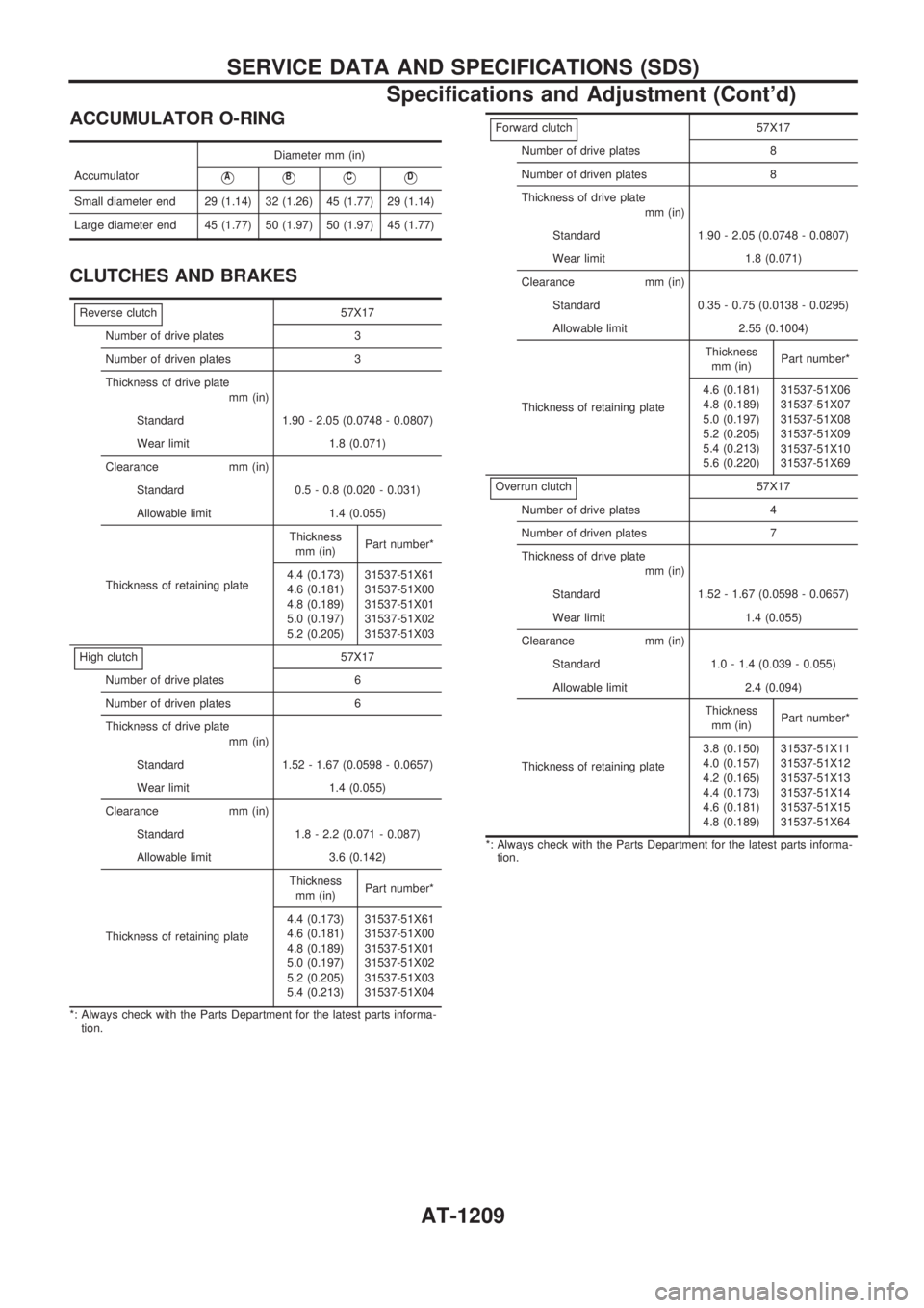
ACCUMULATOR O-RING
AccumulatorDiameter mm (in)VAVBVCVD
Small diameter end 29 (1.14) 32 (1.26) 45 (1.77) 29 (1.14)
Large diameter end 45 (1.77) 50 (1.97) 50 (1.97) 45 (1.77)
CLUTCHES AND BRAKES
Reverse clutch57X17
Number of drive plates 3
Number of driven plates 3
Thickness of drive plate
mm (in)
Standard 1.90 - 2.05 (0.0748 - 0.0807)
Wear limit 1.8 (0.071)
Clearance mm (in)
Standard 0.5 - 0.8 (0.020 - 0.031)
Allowable limit 1.4 (0.055)
Thickness of retaining plateThickness
mm (in)Part number*
4.4 (0.173)
4.6 (0.181)
4.8 (0.189)
5.0 (0.197)
5.2 (0.205)31537-51X61
31537-51X00
31537-51X01
31537-51X02
31537-51X03
High clutch
57X17
Number of drive plates 6
Number of driven plates 6
Thickness of drive plate
mm (in)
Standard 1.52 - 1.67 (0.0598 - 0.0657)
Wear limit 1.4 (0.055)
Clearance mm (in)
Standard 1.8 - 2.2 (0.071 - 0.087)
Allowable limit 3.6 (0.142)
Thickness of retaining plateThickness
mm (in)Part number*
4.4 (0.173)
4.6 (0.181)
4.8 (0.189)
5.0 (0.197)
5.2 (0.205)
5.4 (0.213)31537-51X61
31537-51X00
31537-51X01
31537-51X02
31537-51X03
31537-51X04
*: Always check with the Parts Department for the latest parts informa-
tion.
Forward clutch57X17
Number of drive plates 8
Number of driven plates 8
Thickness of drive plate
mm (in)
Standard 1.90 - 2.05 (0.0748 - 0.0807)
Wear limit 1.8 (0.071)
Clearance mm (in)
Standard 0.35 - 0.75 (0.0138 - 0.0295)
Allowable limit 2.55 (0.1004)
Thickness of retaining plateThickness
mm (in)Part number*
4.6 (0.181)
4.8 (0.189)
5.0 (0.197)
5.2 (0.205)
5.4 (0.213)
5.6 (0.220)31537-51X06
31537-51X07
31537-51X08
31537-51X09
31537-51X10
31537-51X69
Overrun clutch
57X17
Number of drive plates 4
Number of driven plates 7
Thickness of drive plate
mm (in)
Standard 1.52 - 1.67 (0.0598 - 0.0657)
Wear limit 1.4 (0.055)
Clearance mm (in)
Standard 1.0 - 1.4 (0.039 - 0.055)
Allowable limit 2.4 (0.094)
Thickness of retaining plateThickness
mm (in)Part number*
3.8 (0.150)
4.0 (0.157)
4.2 (0.165)
4.4 (0.173)
4.6 (0.181)
4.8 (0.189)31537-51X11
31537-51X12
31537-51X13
31537-51X14
31537-51X15
31537-51X64
*: Always check with the Parts Department for the latest parts informa-
tion.
SERVICE DATA AND SPECIFICATIONS (SDS)
Specifications and Adjustment (Cont'd)
AT-1209
Page 212 of 1033
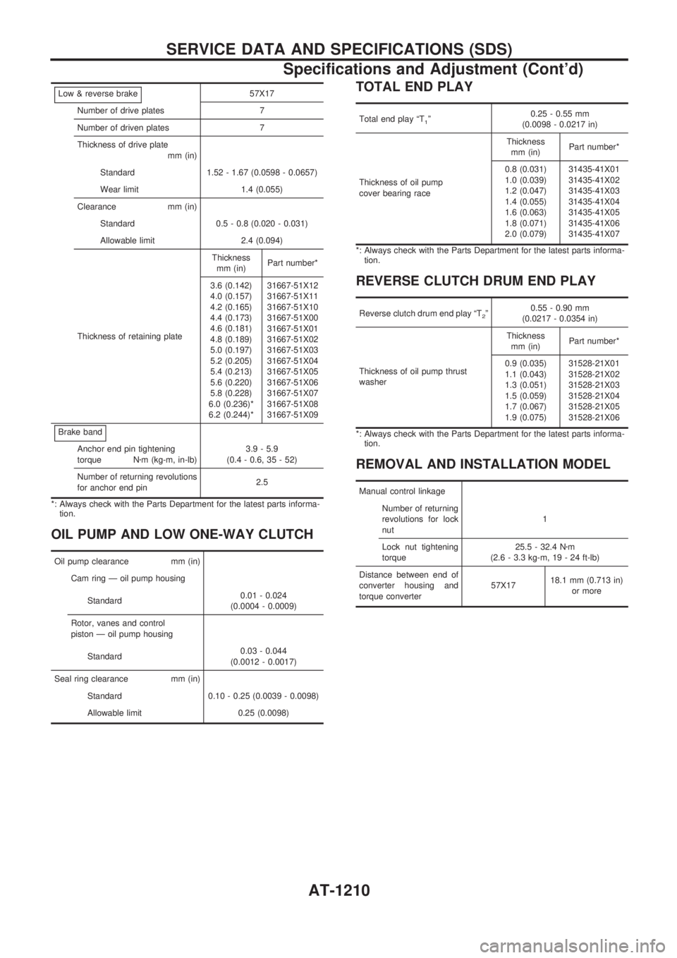
Low & reverse brake57X17
Number of drive plates 7
Number of driven plates 7
Thickness of drive plate
mm (in)
Standard 1.52 - 1.67 (0.0598 - 0.0657)
Wear limit 1.4 (0.055)
Clearance mm (in)
Standard 0.5 - 0.8 (0.020 - 0.031)
Allowable limit 2.4 (0.094)
Thickness of retaining plateThickness
mm (in)Part number*
3.6 (0.142)
4.0 (0.157)
4.2 (0.165)
4.4 (0.173)
4.6 (0.181)
4.8 (0.189)
5.0 (0.197)
5.2 (0.205)
5.4 (0.213)
5.6 (0.220)
5.8 (0.228)
6.0 (0.236)*
6.2 (0.244)*31667-51X12
31667-51X11
31667-51X10
31667-51X00
31667-51X01
31667-51X02
31667-51X03
31667-51X04
31667-51X05
31667-51X06
31667-51X07
31667-51X08
31667-51X09
Brake band
Anchor end pin tightening
torque Nzm (kg-m, in-lb)3.9 - 5.9
(0.4 - 0.6, 35 - 52)
Number of returning revolutions
for anchor end pin2.5
*: Always check with the Parts Department for the latest parts informa-
tion.
OIL PUMP AND LOW ONE-WAY CLUTCH
Oil pump clearance mm (in)
Cam ring Ð oil pump housing
Standard0.01 - 0.024
(0.0004 - 0.0009)
Rotor, vanes and control
piston Ð oil pump housing
Standard0.03 - 0.044
(0.0012 - 0.0017)
Seal ring clearance mm (in)
Standard 0.10 - 0.25 (0.0039 - 0.0098)
Allowable limit 0.25 (0.0098)
TOTAL END PLAY
Total end play ªT1º0.25 - 0.55 mm
(0.0098 - 0.0217 in)
Thickness of oil pump
cover bearing raceThickness
mm (in)Part number*
0.8 (0.031)
1.0 (0.039)
1.2 (0.047)
1.4 (0.055)
1.6 (0.063)
1.8 (0.071)
2.0 (0.079)31435-41X01
31435-41X02
31435-41X03
31435-41X04
31435-41X05
31435-41X06
31435-41X07
*: Always check with the Parts Department for the latest parts informa-
tion.
REVERSE CLUTCH DRUM END PLAY
Reverse clutch drum end play ªT2º0.55 - 0.90 mm
(0.0217 - 0.0354 in)
Thickness of oil pump thrust
washerThickness
mm (in)Part number*
0.9 (0.035)
1.1 (0.043)
1.3 (0.051)
1.5 (0.059)
1.7 (0.067)
1.9 (0.075)31528-21X01
31528-21X02
31528-21X03
31528-21X04
31528-21X05
31528-21X06
*: Always check with the Parts Department for the latest parts informa-
tion.
REMOVAL AND INSTALLATION MODEL
Manual control linkage
Number of returning
revolutions for lock
nut1
Lock nut tightening
torque25.5 - 32.4 Nzm
(2.6 - 3.3 kg-m, 19 - 24 ft-lb)
Distance between end of
converter housing and
torque converter57X1718.1 mm (0.713 in)
or more
SERVICE DATA AND SPECIFICATIONS (SDS)
Specifications and Adjustment (Cont'd)
AT-1210
Page 213 of 1033
BRAKE SYSTEM
SECTION
BR
MODIFICATION NOTICE:
+CONSULT-II is available for all models.
+Service Data and Specifications (SDS) have been changed.
+Wiring Diagrams have been changed.
CONTENTS
TROUBLE DIAGNOSES..................................... 1002
Schematic ........................................................ 1002
Wiring Diagram Ð ABS Ð .............................. 1003Self-diagnosis................................................... 1008
SERVICE DATA AND SPECIFICATIONS (SDS)1010
General Specifications ..................................... 1010
BR
Page 214 of 1033
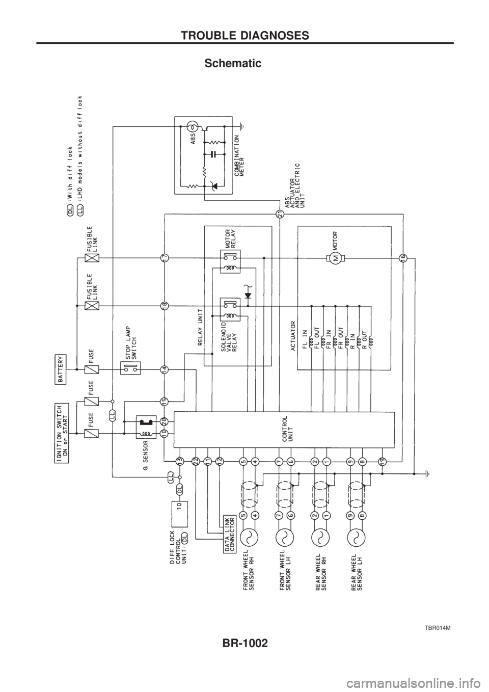
Schematic
TBR014M
TROUBLE DIAGNOSES
BR-1002
Page 215 of 1033
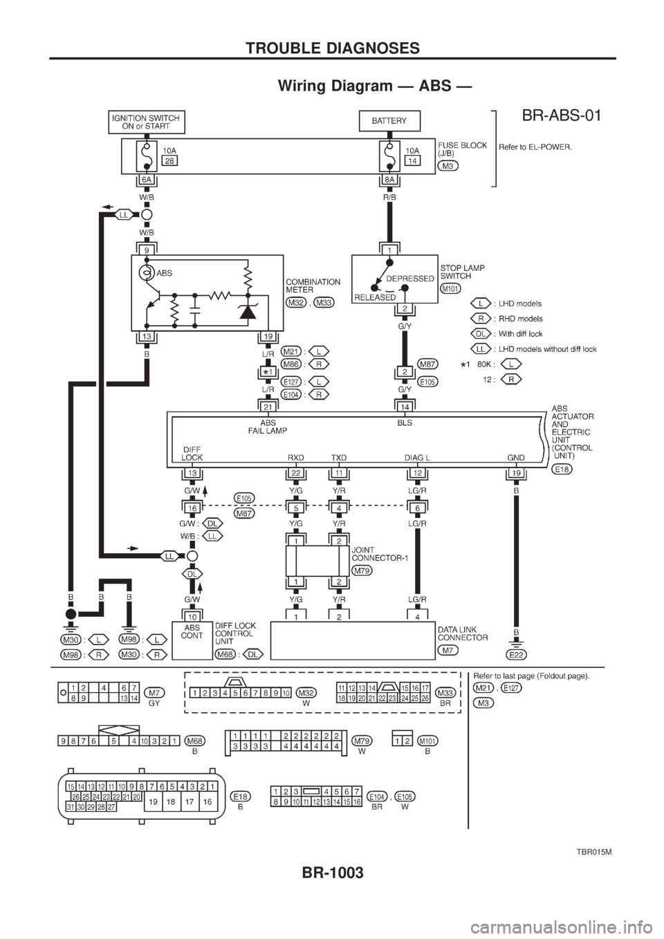
Wiring Diagram Ð ABS Ð
TBR015M
TROUBLE DIAGNOSES
BR-1003
Page 216 of 1033
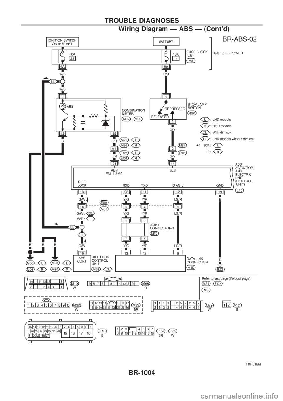
TBR016M
TROUBLE DIAGNOSES
Wiring Diagram Ð ABS Ð (Cont'd)
BR-1004
Page 217 of 1033
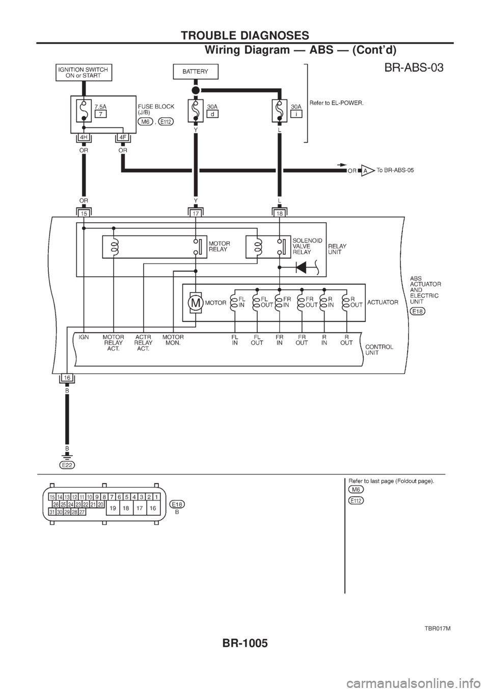
TBR017M
TROUBLE DIAGNOSES
Wiring Diagram Ð ABS Ð (Cont'd)
BR-1005
Page 218 of 1033
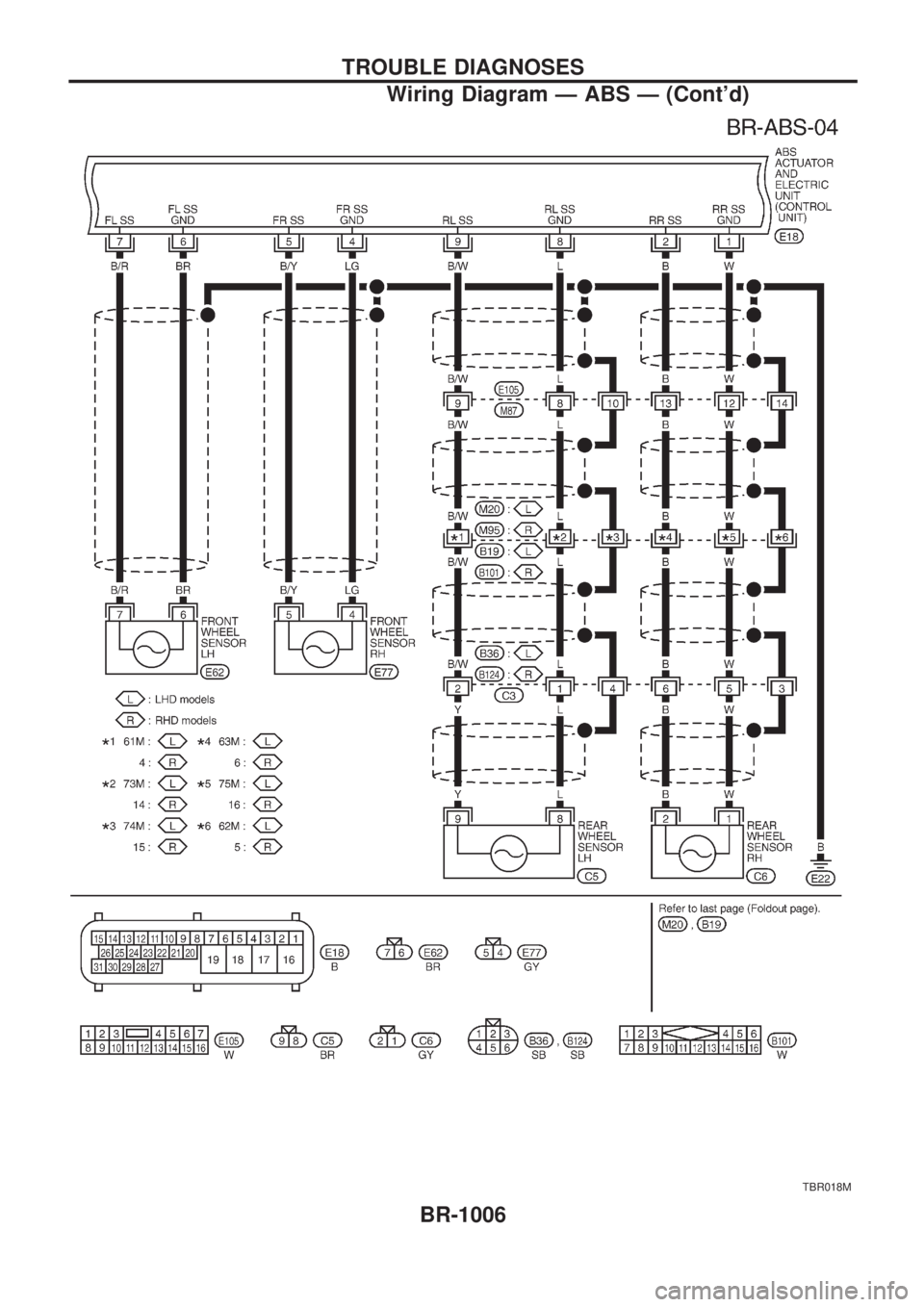
TBR018M
TROUBLE DIAGNOSES
Wiring Diagram Ð ABS Ð (Cont'd)
BR-1006
Page 219 of 1033
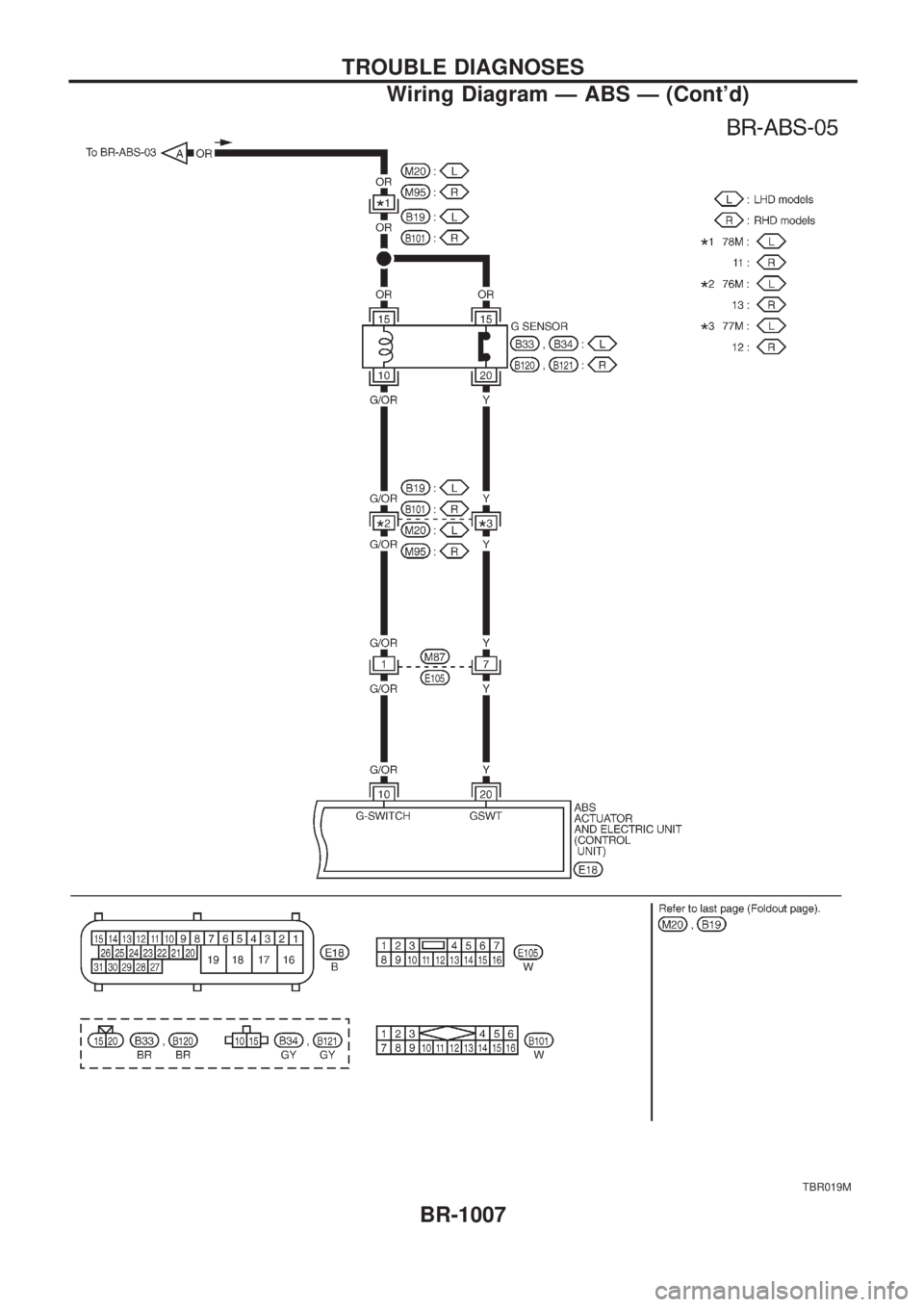
TBR019M
TROUBLE DIAGNOSES
Wiring Diagram Ð ABS Ð (Cont'd)
BR-1007
Page 220 of 1033
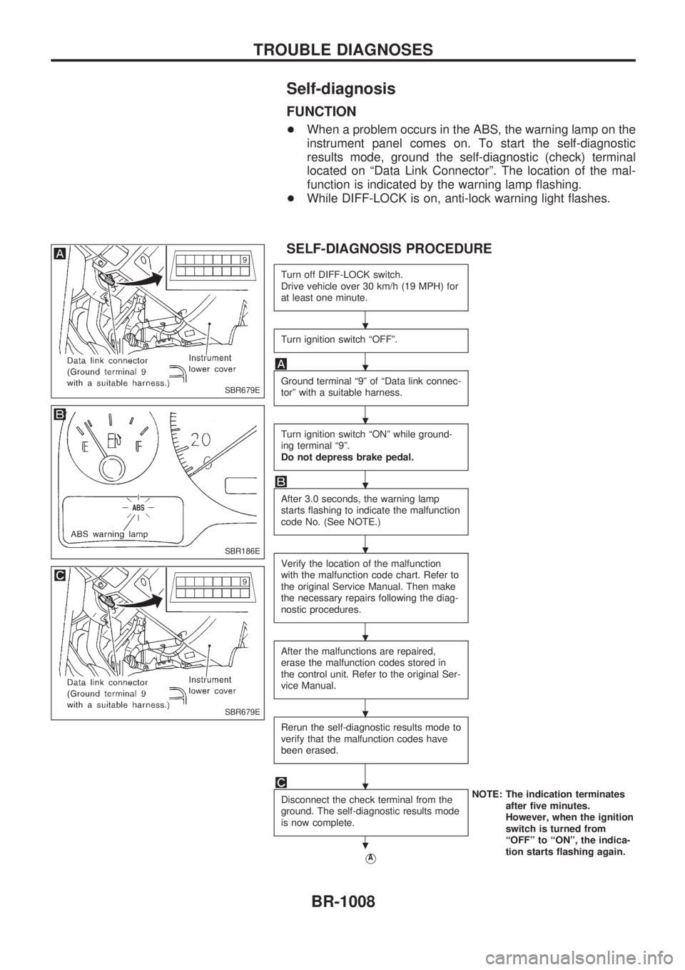
Self-diagnosis
FUNCTION
+When a problem occurs in the ABS, the warning lamp on the
instrument panel comes on. To start the self-diagnostic
results mode, ground the self-diagnostic (check) terminal
located on ªData Link Connectorº. The location of the mal-
function is indicated by the warning lamp flashing.
+While DIFF-LOCK is on, anti-lock warning light flashes.
SELF-DIAGNOSIS PROCEDURE
Turn off DIFF-LOCK switch.
Drive vehicle over 30 km/h (19 MPH) for
at least one minute.
Turn ignition switch ªOFFº.
Ground terminal ª9º of ªData link connec-
torº with a suitable harness.
Turn ignition switch ªONº while ground-
ing terminal ª9º.
Do not depress brake pedal.
After 3.0 seconds, the warning lamp
starts flashing to indicate the malfunction
code No. (See NOTE.)
Verify the location of the malfunction
with the malfunction code chart. Refer to
the original Service Manual. Then make
the necessary repairs following the diag-
nostic procedures.
After the malfunctions are repaired,
erase the malfunction codes stored in
the control unit. Refer to the original Ser-
vice Manual.
Rerun the self-diagnostic results mode to
verify that the malfunction codes have
been erased.
Disconnect the check terminal from the
ground. The self-diagnostic results mode
is now complete.NOTE: The indication terminates
after five minutes.
However, when the ignition
switch is turned from
ªOFFº to ªONº, the indica-
tion starts flashing again.
VA
SBR679E
SBR186E
SBR679E
.
.
.
.
.
.
.
.
.
TROUBLE DIAGNOSES
BR-1008
Trending: diagram, power steering, fuel consumption, ground clearance, tire type, change time, brakes


