NISSAN PATROL 2000 Electronic Repair Manual
PATROL 2000
NISSAN
NISSAN
https://www.carmanualsonline.info/img/5/57367/w960_57367-0.png
NISSAN PATROL 2000 Electronic Repair Manual
Trending: coolant reservoir, service indicator, Audio, ground clearance, oil pressure, radiator, sensor
Page 601 of 1033
System Description
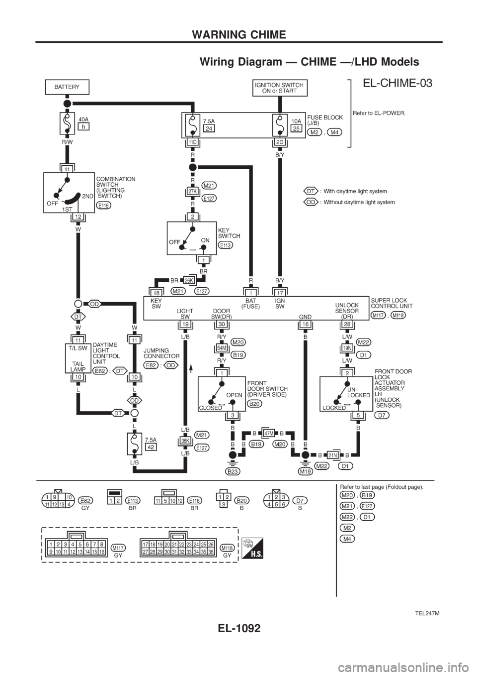
The warning chime is combined with the super lock control unit.
Both the ignition key and light warning chime will not sound, when ignition switch in the ON or START posi-
tion (when power supply exists at super lock control unit terminal
V17).
IGNITION KEY WARNING CHIME
With the key in the ignition key cylinder, the ignition switch in the OFF or ACC position, and the driver's door
open and locked, the warning chime will sound. Power is supplied
+from key switch terminal
V1
+to super lock control unit terminalV18.
Ground is supplied
+through driver front door switch terminal
V1
+to super lock control unit terminalV30, and
+through front door lock actuator assembly (driver side) (unlock sensor) terminal
V2
+to super lock control unit terminalV28.
LIGHT WARNING CHIME
With ignition switch in the OFF or ACC position, driver's door open, and lighting switch in 1ST or 2ND
position, warning chime will sound. Power is supplied
+from combination switch terminal
V12
+to super lock control unit terminalV19.
Ground is supplied
+through driver front door switch terminal
V1
+to super lock control unit terminalV30.
WARNING CHIME
EL-1091
Page 602 of 1033
Wiring Diagram Ð CHIME Ð/LHD Models
TEL247M
WARNING CHIME
EL-1092
Page 603 of 1033
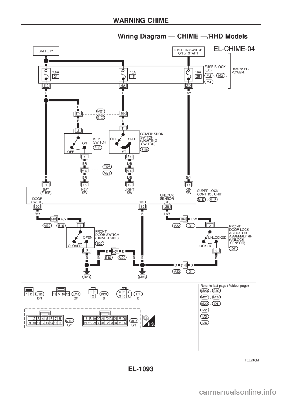
Wiring Diagram Ð CHIME Ð/RHD Models
TEL248M
WARNING CHIME
EL-1093
Page 604 of 1033
Trouble Diagnoses
SYMPTOM CHART
REFERENCE PAGE EL-1094 EL-1095 EL-1095 EL-1096
SYMPTOM
DIAGNOSTIC PROCEDURE 1
(Lighting switch input signal check)
DIAGNOSTIC PROCEDURE 2
(Key switch input signal check)
DIAGNOSTIC PROCEDURE 3
(Door unlock sensor check)
DIAGNOSTIC PROCEDURE 4
Light warning chime does not acti-
vate.XX
Ignition key warning chime does not
activate.XXX
All warning chimes do not activate.X
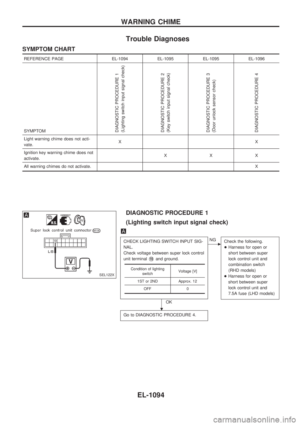
DIAGNOSTIC PROCEDURE 1
(Lighting switch input signal check)
CHECK LIGHTING SWITCH INPUT SIG-
NAL.
Check voltage between super lock control
unit terminal
V19and ground.
OK
cNG
Check the following.
+Harness for open or
short between super
lock control unit and
combination switch
(RHD models)
+Harness for open or
short between super
lock control unit and
7.5A fuse (LHD models)
Go to DIAGNOSTIC PROCEDURE 4.
Condition of lighting
switchVoltage [V]
1ST or 2ND Approx. 12
OFF 0
SEL122X
.
WARNING CHIME
EL-1094
Page 605 of 1033
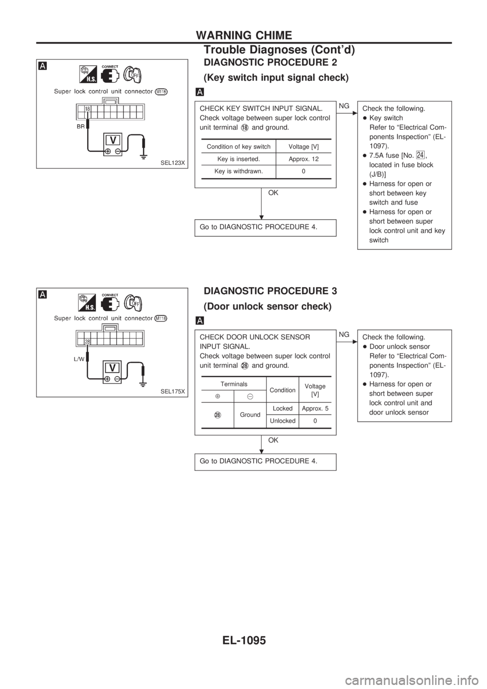
DIAGNOSTIC PROCEDURE 2
(Key switch input signal check)
CHECK KEY SWITCH INPUT SIGNAL.
Check voltage between super lock control
unit terminal
V18and ground.
OK
cNG
Check the following.
+Key switch
Refer to ªElectrical Com-
ponents Inspectionº (EL-
1097).
+7.5A fuse [No.
24,
located in fuse block
(J/B)]
+Harness for open or
short between key
switch and fuse
+Harness for open or
short between super
lock control unit and key
switch
Go to DIAGNOSTIC PROCEDURE 4.
Condition of key switch Voltage [V]
Key is inserted. Approx. 12
Key is withdrawn. 0
DIAGNOSTIC PROCEDURE 3
(Door unlock sensor check)
CHECK DOOR UNLOCK SENSOR
INPUT SIGNAL.
Check voltage between super lock control
unit terminal
V28and ground.
OK
cNG
Check the following.
+Door unlock sensor
Refer to ªElectrical Com-
ponents Inspectionº (EL-
1097).
+Harness for open or
short between super
lock control unit and
door unlock sensor
Go to DIAGNOSTIC PROCEDURE 4.
Terminals
ConditionVoltage
[V]
Å@
V28GroundLocked Approx. 5
Unlocked 0
SEL123X
SEL175X
.
.
WARNING CHIME
Trouble Diagnoses (Cont'd)
EL-1095
Page 606 of 1033
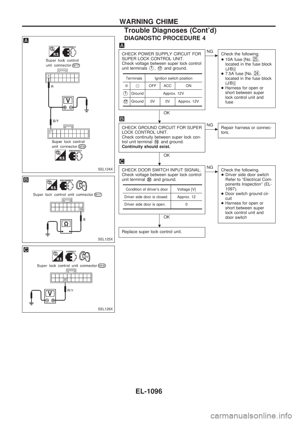
DIAGNOSTIC PROCEDURE 4
CHECK POWER SUPPLY CIRCUIT FOR
SUPER LOCK CONTROL UNIT.
Check voltage between super lock control
unit terminals
V1,V17and ground.
OK
cNG
Check the following.
+10A fuse [No.
25,
located in the fuse block
(J/B)]
+7.5A fuse [No.
24,
located in the fuse block
(J/B)]
+Harness for open or
short between super
lock control unit and
fuse
CHECK GROUND CIRCUIT FOR SUPER
LOCK CONTROL UNIT.
Check continuity between super lock con-
trol unit terminal
V16and ground.
Continuity should exist.
OK
cNG
Repair harness or connec-
tors.
CHECK DOOR SWITCH INPUT SIGNAL.
Check voltage between super lock control
unit terminal
V30and ground.
OK
cNG
Check the following.
+Driver side door switch
Refer to ªElectrical Com-
ponents Inspectionº (EL-
1097).
+Door switch ground cir-
cuit
+Harness for open or
short between super
lock control unit and
door switch
Replace super lock control unit.
Terminals Ignition switch position
Å@OFF ACC ON
V1Ground Approx. 12V
V17Ground 0V 0V Approx. 12V
Condition of driver's door Voltage [V]
Driver side door is closed. Approx. 12
Driver side door is open. 0
SEL124X
SEL125X
SEL126X
.
.
.
WARNING CHIME
Trouble Diagnoses (Cont'd)
EL-1096
Page 607 of 1033
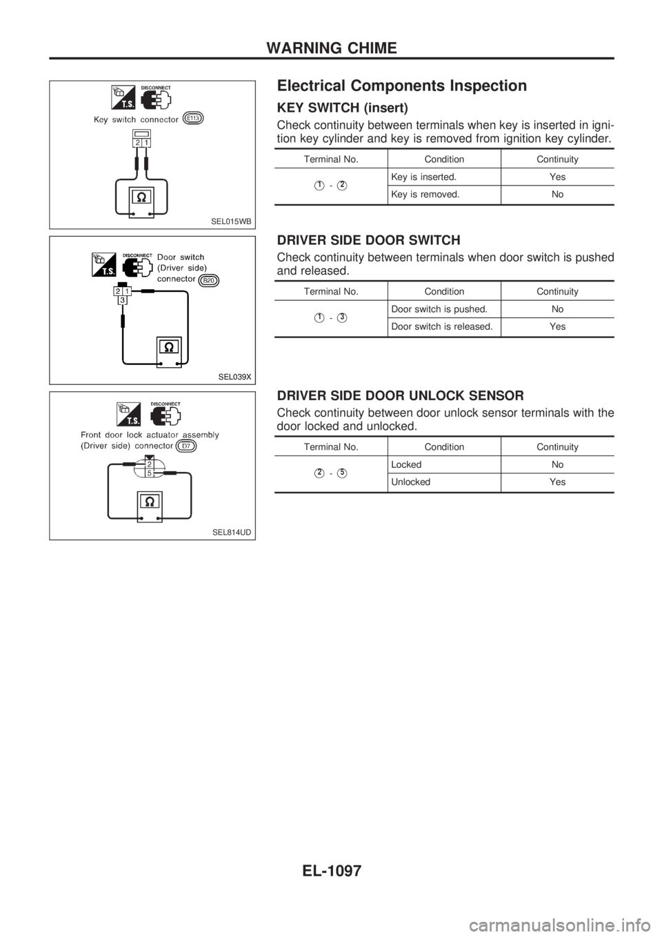
Electrical Components Inspection
KEY SWITCH (insert)
Check continuity between terminals when key is inserted in igni-
tion key cylinder and key is removed from ignition key cylinder.
Terminal No. Condition Continuity
V1-V2Key is inserted. Yes
Key is removed. No
DRIVER SIDE DOOR SWITCH
Check continuity between terminals when door switch is pushed
and released.
Terminal No. Condition Continuity
V1-V3Door switch is pushed. No
Door switch is released. Yes
DRIVER SIDE DOOR UNLOCK SENSOR
Check continuity between door unlock sensor terminals with the
door locked and unlocked.
Terminal No. Condition Continuity
V2-V5Locked No
Unlocked Yes
SEL015WB
SEL039X
SEL814UD
WARNING CHIME
EL-1097
Page 608 of 1033
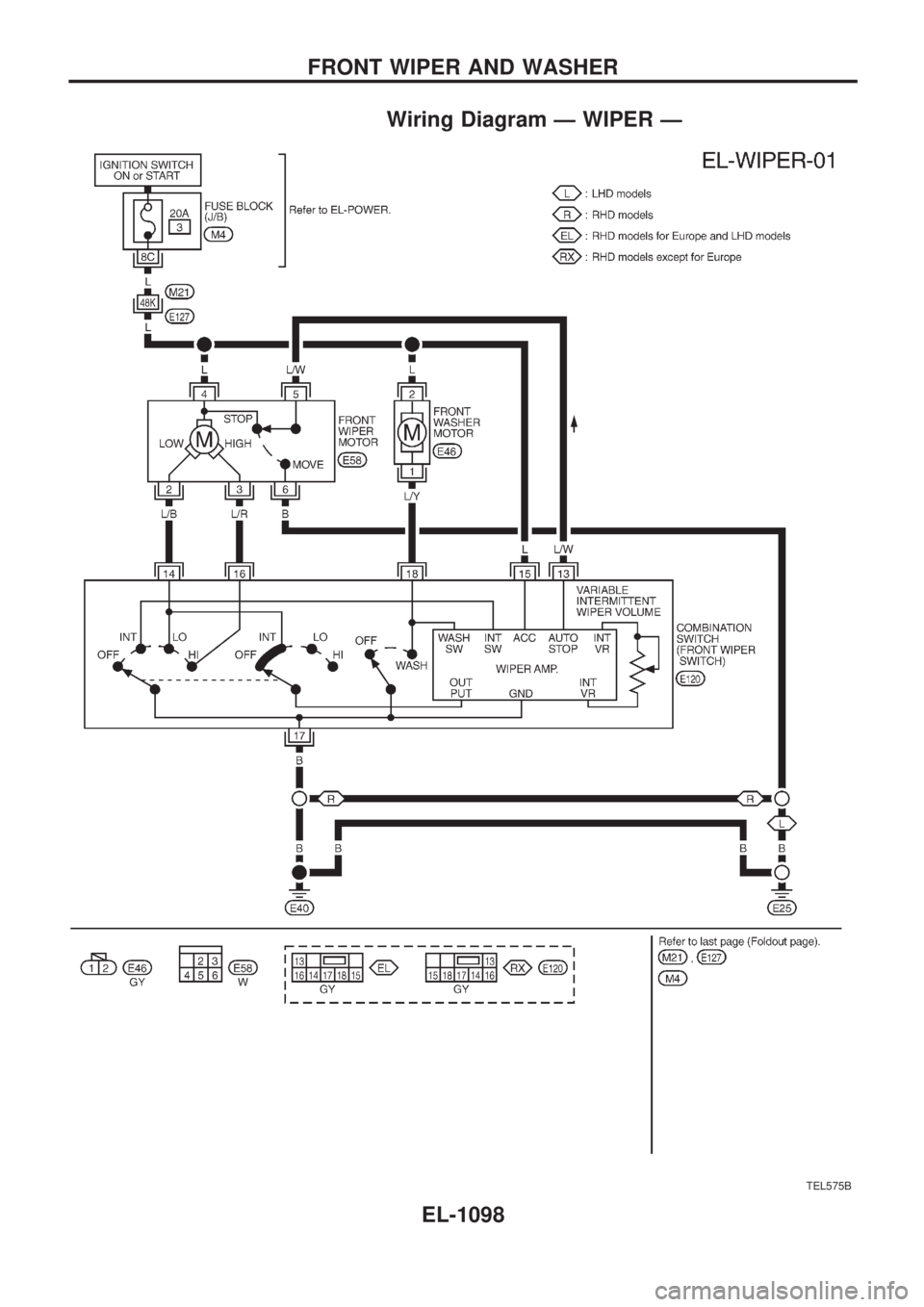
Wiring Diagram Ð WIPER Ð
TEL575B
FRONT WIPER AND WASHER
EL-1098
Page 609 of 1033
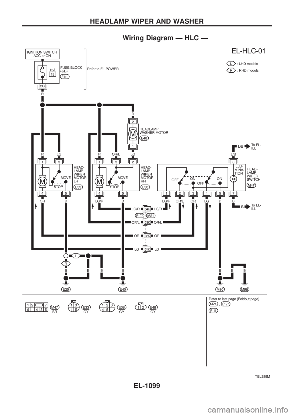
Wiring Diagram Ð HLC Ð
TEL289M
HEADLAMP WIPER AND WASHER
EL-1099
Page 610 of 1033
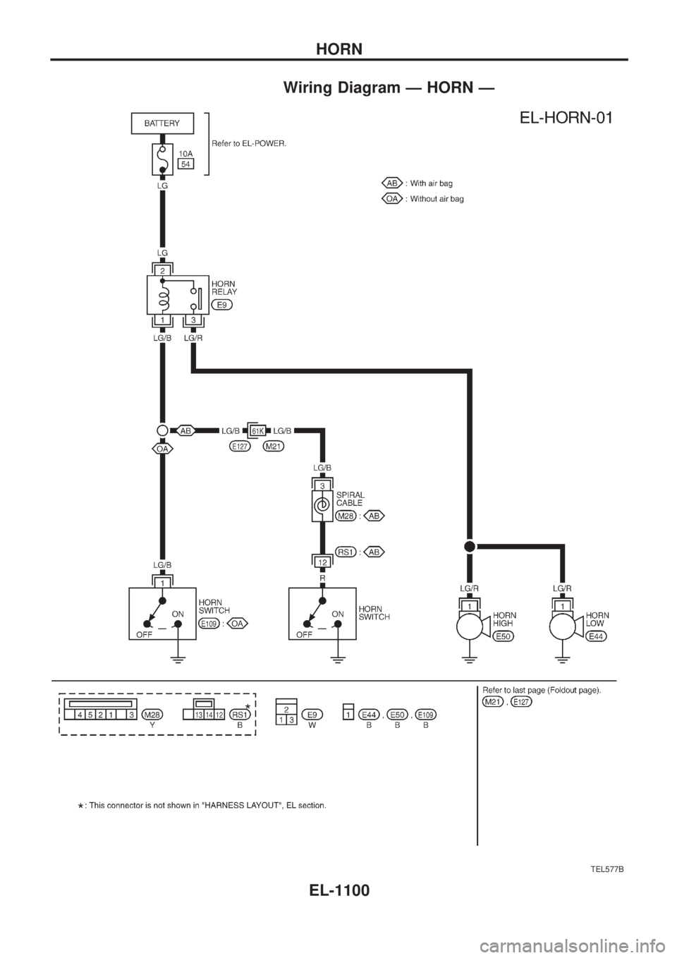
Wiring Diagram Ð HORN Ð
TEL577B
HORN
EL-1100
Trending: length, horn, service schedule, compression ratio, checking oil, jump start, SOLENOID

