NISSAN PATROL 2000 Electronic Repair Manual
PATROL 2000
NISSAN
NISSAN
https://www.carmanualsonline.info/img/5/57367/w960_57367-0.png
NISSAN PATROL 2000 Electronic Repair Manual
Trending: headlamp, fuel pressure, coolant, wheel torque, mirror, clutch, wheel bolts
Page 611 of 1033
System Description
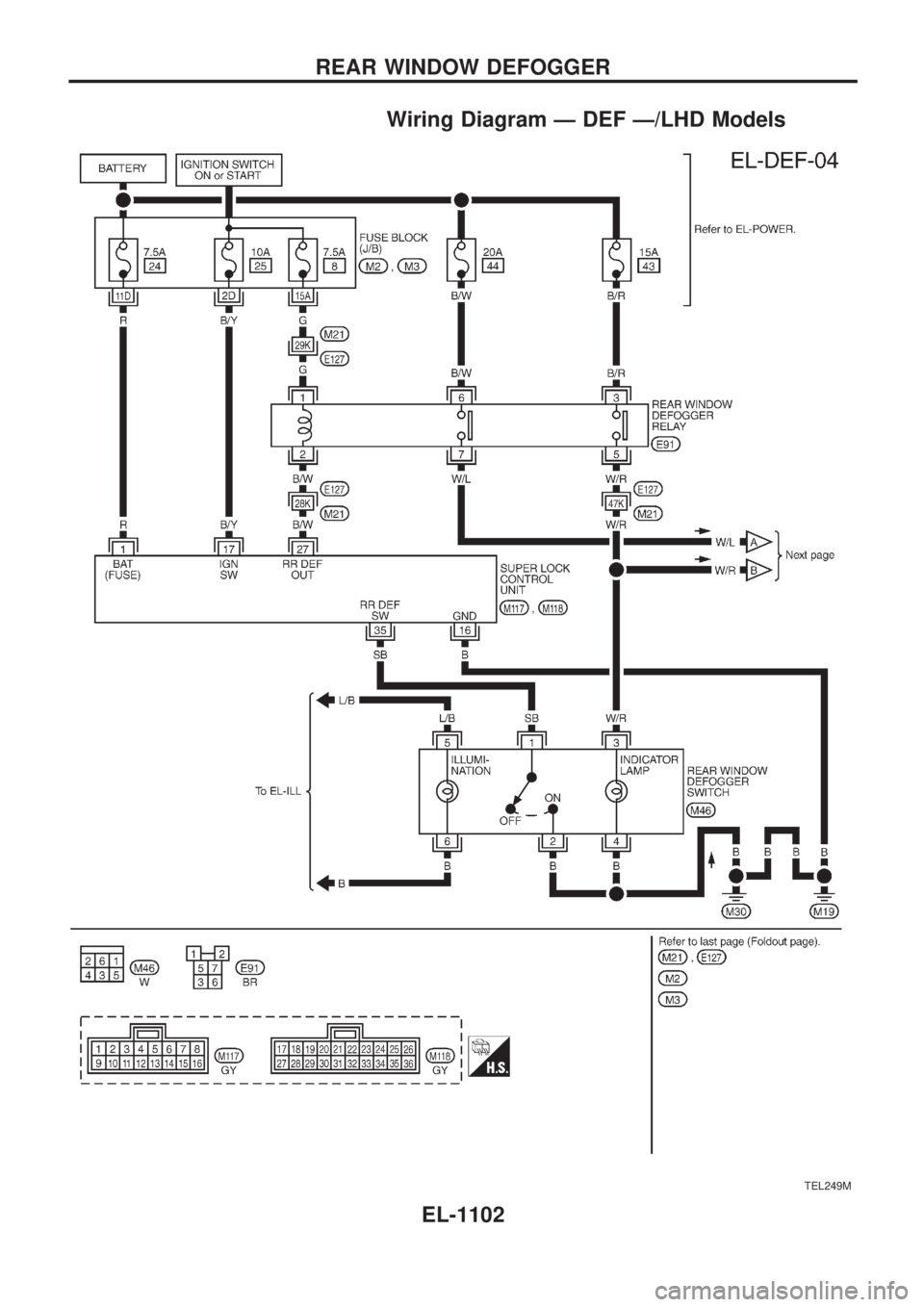
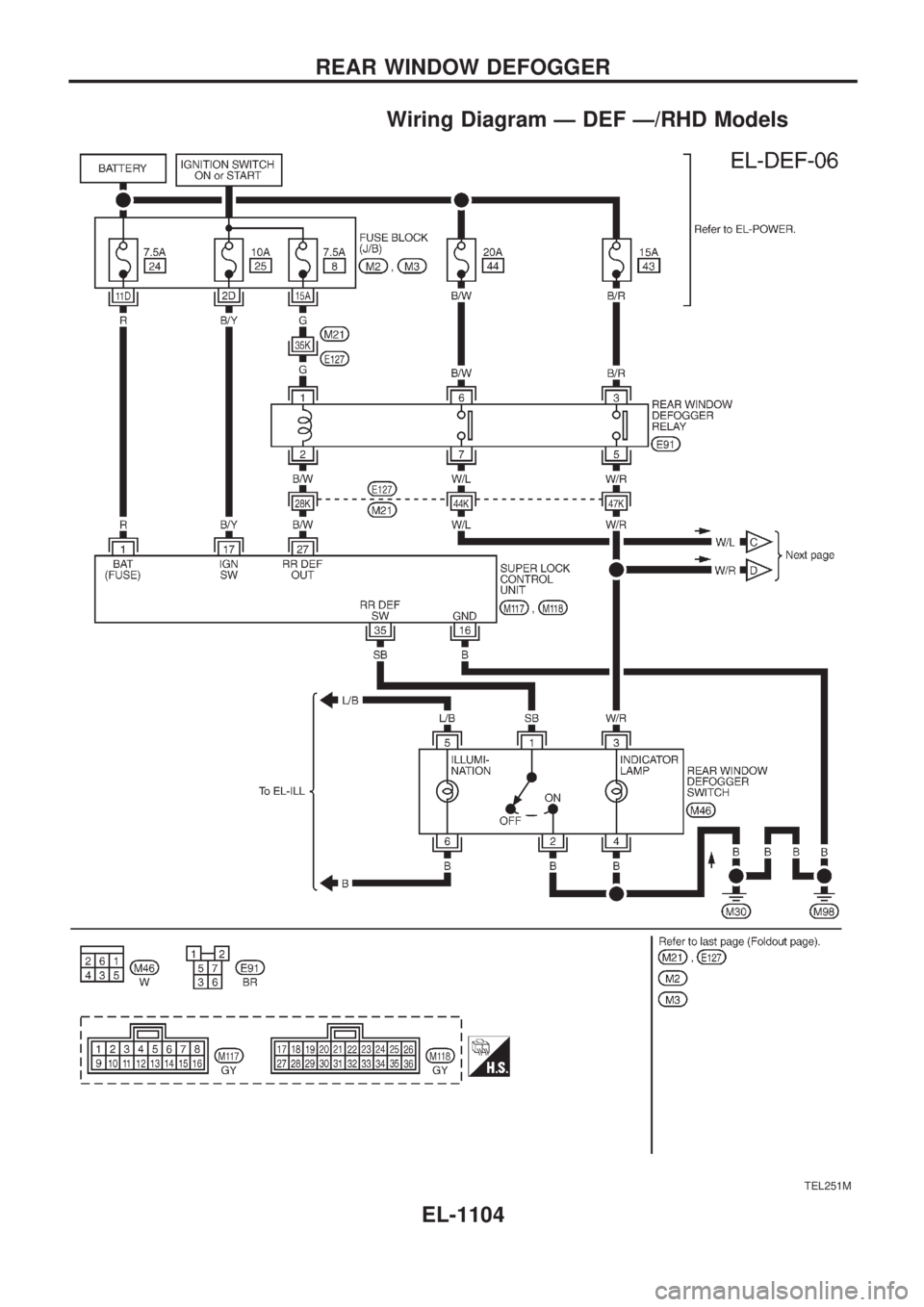
The rear window defogger system is controlled by the super lock control unit. The rear window defogger
operates only for approximately 15 minutes.
Power is supplied at all times
+to rear window defogger relay terminal
V3
+through 15A fuse (No.43, located in the fuse and fusible link box),
+to rear window defogger relay terminal
V6
+through 20A fuse (No.44, located in the fuse and fusible link box) and
+to super lock control unit terminal
V1
+through 7.5A fuse [No.24, located in the fuse block (J/B)].
With the ignition switch in the ON or START position, power is supplied
+to the rear window defogger relay terminal
V1
+through 7.5A fuse [No.8, located in the fuse block (J/B)] and
+to super lock control unit terminal
V17
+through 10A fuse [No.25, located in the fuse block (J/B)].
Ground is supplied to terminal
V2of the rear window defogger switch through body grounds.
When the rear window defogger switch is turned ON, ground is supplied
+through terminal
V1of the rear window defogger switch
+to super lock control unit terminal
V35.
Terminal
V27of the super lock control unit then supplies ground to the rear window defogger relay terminal
V2.
With power and ground supplied, the rear window defogger relay is energized.
Power is supplied
+through terminals
V5andV7of the rear window defogger relay
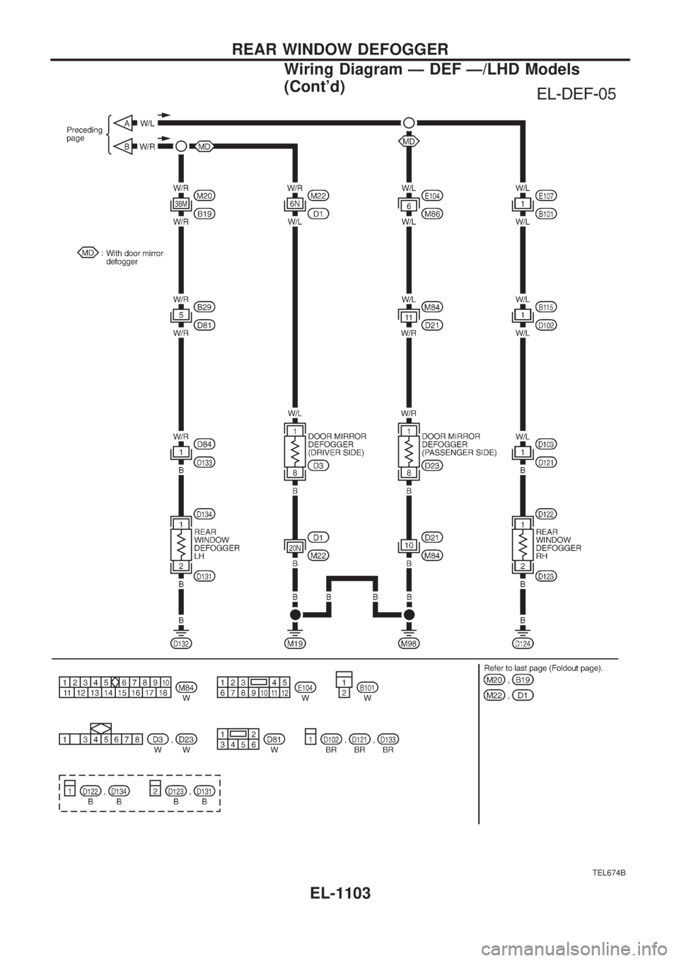
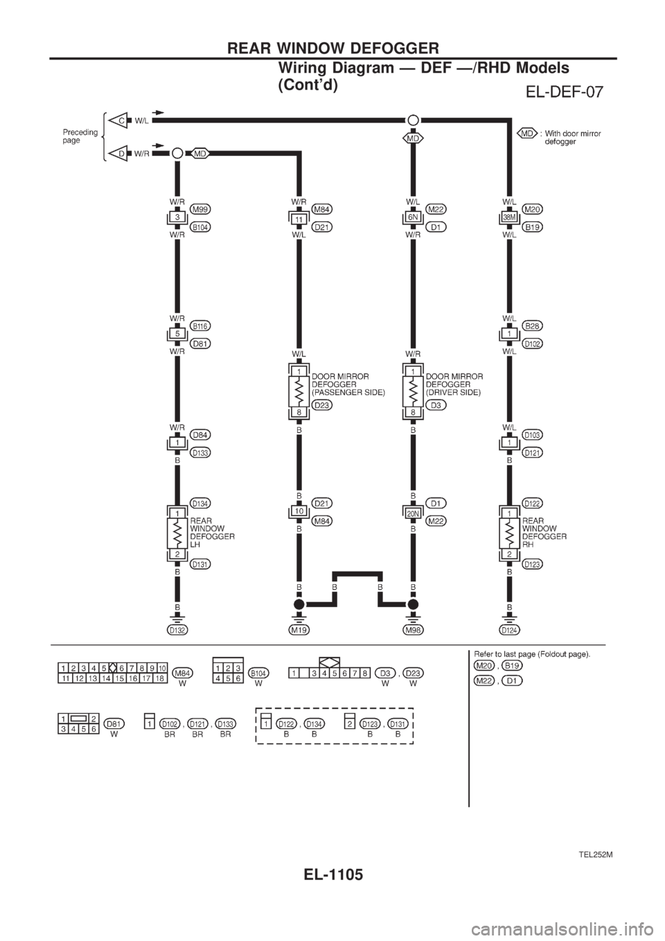
+to the rear window defogger and door mirror defogger (with door mirror defogger).
The rear window defogger has an independent ground.
With power and ground supplied, the rear window defogger filaments heat and defog the rear window.
When the system is activated, the rear window defogger indicator illuminates in the rear window defogger
switch.
Power is supplied
+to terminal
V3of the rear window defogger switch
+from terminal
V5of the rear window defogger relay.
Terminal
V4of the rear window defogger switch is grounded through body grounds.
REAR WINDOW DEFOGGER
EL-1101
Page 612 of 1033
Wiring Diagram Ð DEF Ð/LHD Models
TEL249M
REAR WINDOW DEFOGGER
EL-1102
Page 613 of 1033
TEL674B
REAR WINDOW DEFOGGER
Wiring Diagram Ð DEF Ð/LHD Models
(Cont'd)
EL-1103
Page 614 of 1033
Wiring Diagram Ð DEF Ð/RHD Models
TEL251M
REAR WINDOW DEFOGGER
EL-1104
Page 615 of 1033
TEL252M
REAR WINDOW DEFOGGER
Wiring Diagram Ð DEF Ð/RHD Models
(Cont'd)
EL-1105
Page 616 of 1033
Trouble Diagnoses
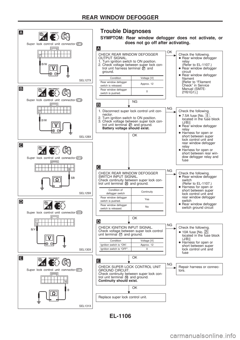
SYMPTOM: Rear window defogger does not activate, or
does not go off after activating.
CHECK REAR WINDOW DEFOGGER
OUTPUT SIGNAL.
1. Turn ignition switch to ON position.
2. Check voltage between super lock con-
trol unit harness terminal
V27and
ground.
NG
cOK
Check the following.
+Rear window defogger
relay
(Refer to EL-1107.)
+Rear window defogger
circuit
+Rear window defogger
filament
[Refer to ªFilament
Checkº in Service
Manual (SM7E-
2Y61G1).]
1. Disconnect super lock control unit con-
nector.
2. Turn ignition switch to ON position.
3. Check voltage between super lock con-
trol unit terminal
V27and ground.
Battery voltage should exist.
OK
cNG
Check the following.
+7.5A fuse [No.
8,
located in the fuse block
(J/B)]
+Rear window defogger
relay
+Harness for open or
short between super
lock control unit and
rear window defogger
relay
+Harness for open or
short between rear win-
dow defogger relay and
fuse
CHECK REAR WINDOW DEFOGGER
SWITCH INPUT SIGNAL.
Check continuity between super lock con-
trol unit terminal
V35and ground.
OK
cNG
Check the following.
+Rear window defogger
switch
(Refer to EL-1107.)
+Harness for open or
short between super
lock control unit and
rear window defogger
switch
+Rear window defogger
switch ground circuit
CHECK IGNITION INPUT SIGNAL.
Check voltage between super lock control
unit terminal
V17and ground.
OK
cNG
Check the following.
+10A fuse [No.
25located in the fuse block
(J/B)]
+Harness for open or
short between super
lock control unit and
fuse
CHECK SUPER LOCK CONTROL UNIT
GROUND CIRCUIT.
Check continuity between super lock con-
trol unit terminal
V16and ground.
Continuity should exist.
OK
cNG
Repair harness or connec-
tors.
Replace super lock control unit.
Condition Voltage [V]
Rear window defogger
switch is released.Approx. 12
Rear window defogger
switch is pushed.0
Condition of
defogger switchContinuity
Rear window defogger
switch is pushed.Yes
Rear window defogger
switch is released.No
Condition Voltage [V]
Ignition switch is ªONº. Approx. 12
Ignition switch is ªOFFº. 0
SEL127X
SEL128X
SEL129X
SEL130X
SEL131X
.
.
.
.
.
REAR WINDOW DEFOGGER
EL-1106
Page 617 of 1033
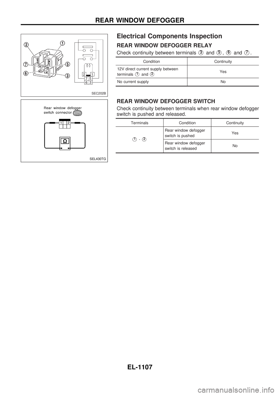
Electrical Components Inspection
REAR WINDOW DEFOGGER RELAY
Check continuity between terminalsV3andV5,V6andV7.
Condition Continuity
12V direct current supply between
terminals
V1andV2Yes
No current supply No
REAR WINDOW DEFOGGER SWITCH
Check continuity between terminals when rear window defogger
switch is pushed and released.
Terminals Condition Continuity
V1-V2
Rear window defogger
switch is pushedYes
Rear window defogger
switch is releasedNo
SEC202B
SEL430TG
REAR WINDOW DEFOGGER
EL-1107
Page 618 of 1033
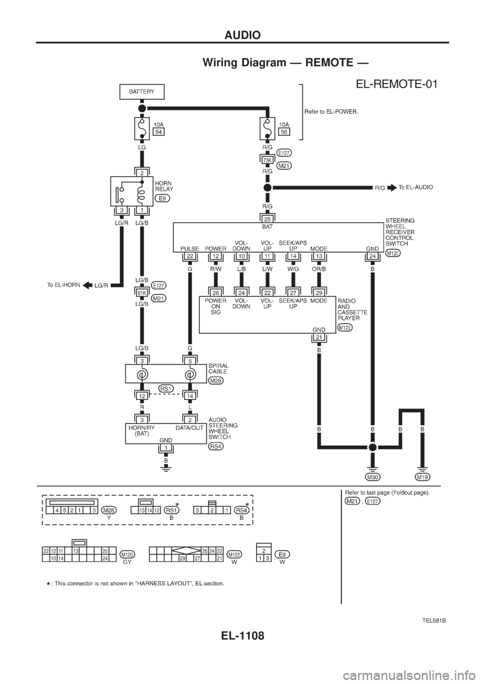
Wiring Diagram Ð REMOTE Ð
TEL581B
AUDIO
EL-1108
Page 619 of 1033
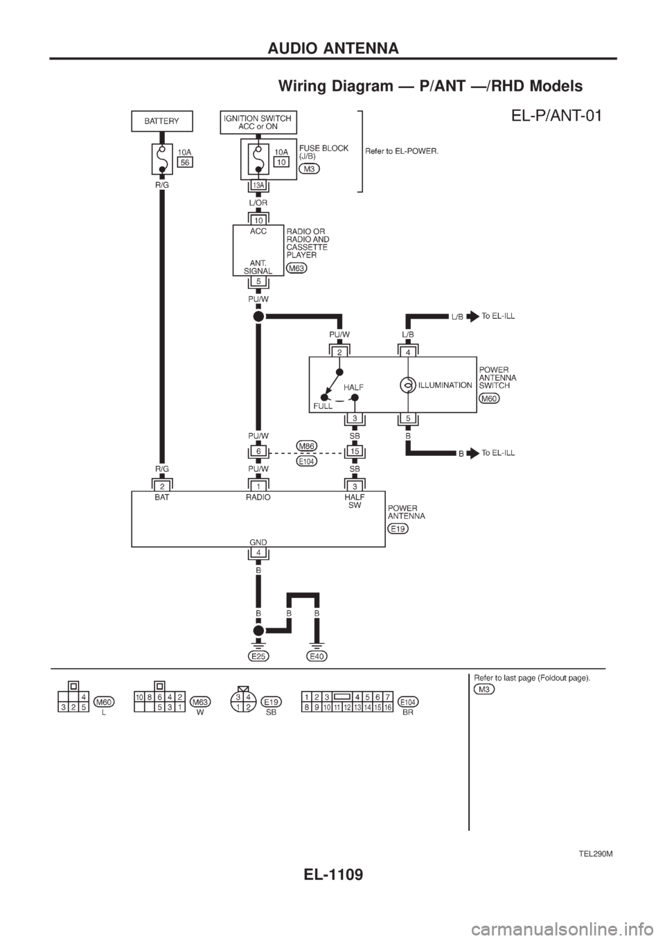
Wiring Diagram Ð P/ANT Ð/RHD Models
TEL290M
AUDIO ANTENNA
EL-1109
Page 620 of 1033
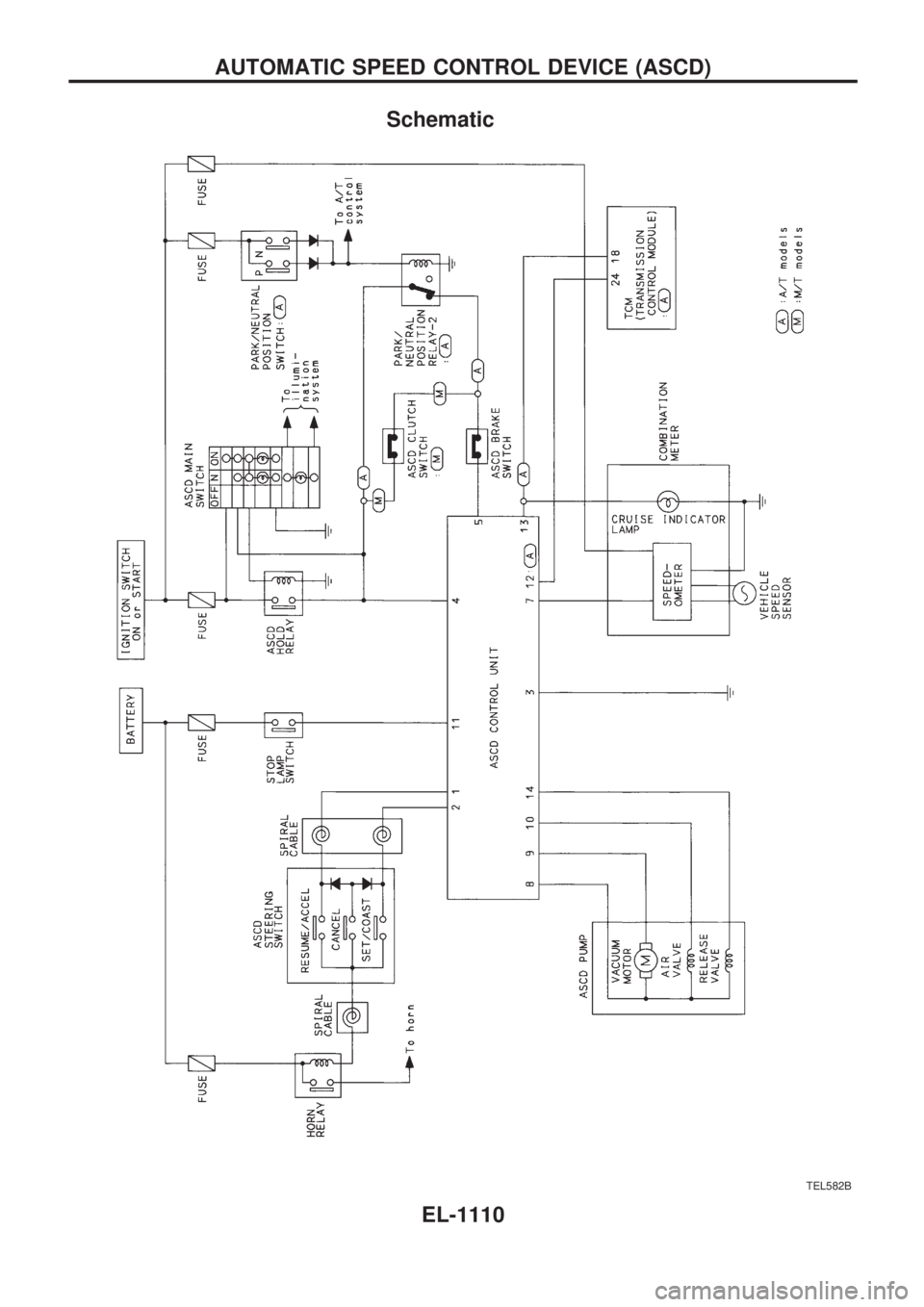
Schematic
TEL582B
AUTOMATIC SPEED CONTROL DEVICE (ASCD)
EL-1110
Trending: checking oil, tires, wiring diagram, jack points, sensor, emergency towing, suspension

