NISSAN PATROL 2000 Electronic Repair Manual
Manufacturer: NISSAN, Model Year: 2000, Model line: PATROL, Model: NISSAN PATROL 2000Pages: 1033, PDF Size: 30.71 MB
Page 651 of 1033
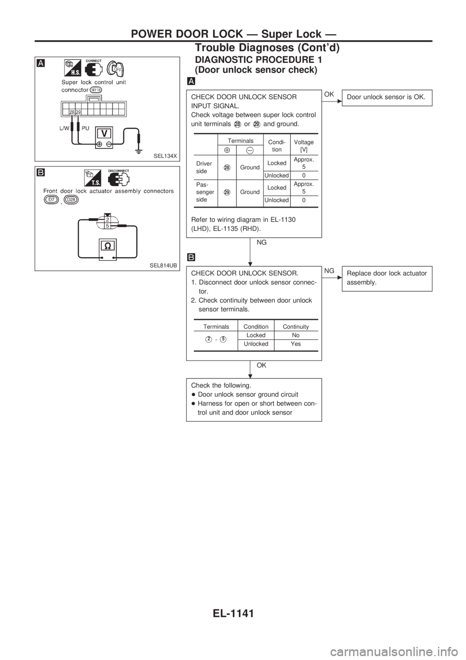
DIAGNOSTIC PROCEDURE 1
(Door unlock sensor check)
CHECK DOOR UNLOCK SENSOR
INPUT SIGNAL.
Check voltage between super lock control
unit terminals
V28orV29and ground.
Refer to wiring diagram in EL-1130
(LHD), EL-1135 (RHD).
NG
cOK
Door unlock sensor is OK.
CHECK DOOR UNLOCK SENSOR.
1. Disconnect door unlock sensor connec-
tor.
2. Check continuity between door unlock
sensor terminals.
OK
cNG
Replace door lock actuator
assembly.
Check the following.
+Door unlock sensor ground circuit
+Harness for open or short between con-
trol unit and door unlock sensor
Terminals
Condi-
tionVoltage
[V]
Å@
Driver
sideV28GroundLockedApprox.
5
Unlocked 0
Pas-
senger
side
V29GroundLockedApprox.
5
Unlocked 0
Terminals Condition Continuity
V2-V5Locked No
Unlocked Yes
SEL134X
SEL814UB.
.
POWER DOOR LOCK Ð Super Lock Ð
Trouble Diagnoses (Cont'd)
EL-1141
Page 652 of 1033
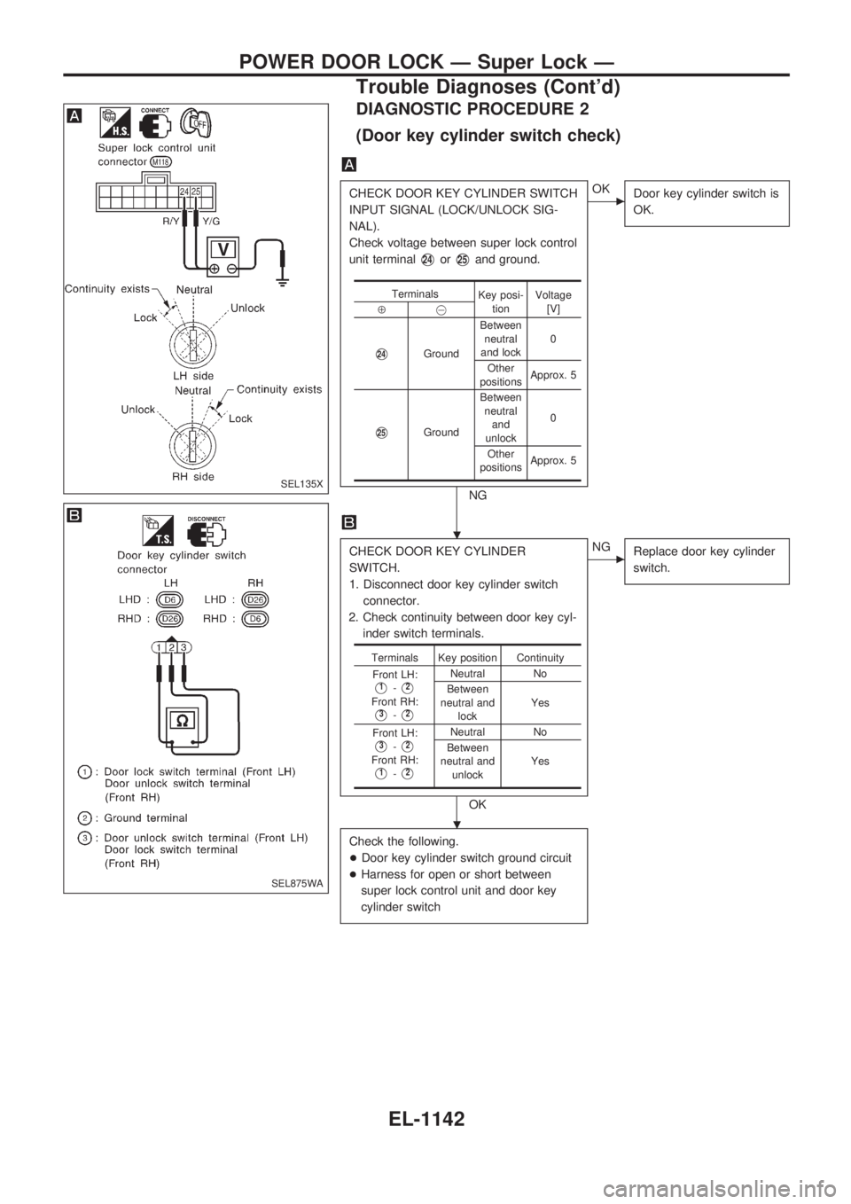
DIAGNOSTIC PROCEDURE 2
(Door key cylinder switch check)
CHECK DOOR KEY CYLINDER SWITCH
INPUT SIGNAL (LOCK/UNLOCK SIG-
NAL).
Check voltage between super lock control
unit terminal
V24orV25and ground.
NG
cOK
Door key cylinder switch is
OK.
CHECK DOOR KEY CYLINDER
SWITCH.
1. Disconnect door key cylinder switch
connector.
2. Check continuity between door key cyl-
inder switch terminals.
OK
cNG
Replace door key cylinder
switch.
Check the following.
+Door key cylinder switch ground circuit
+Harness for open or short between
super lock control unit and door key
cylinder switch
Terminals
Key posi-
tionVoltage
[V]
Å@
V24GroundBetween
neutral
and lock0
Other
positionsApprox. 5
V25GroundBetween
neutral
and
unlock0
Other
positionsApprox. 5
Terminals Key position Continuity
Front LH:
V1-V2
Front RH:
V3-V2
Neutral No
Between
neutral and
lockYes
Front LH:
V3-V2
Front RH:
V1-V2
Neutral No
Between
neutral and
unlockYes
SEL135X
SEL875WA
.
.
POWER DOOR LOCK Ð Super Lock Ð
Trouble Diagnoses (Cont'd)
EL-1142
Page 653 of 1033
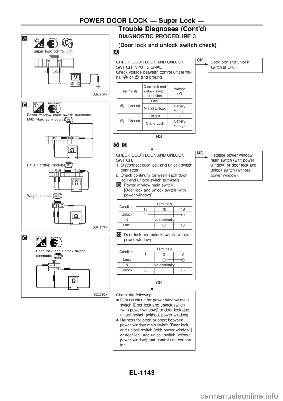
DIAGNOSTIC PROCEDURE 3
(Door lock and unlock switch check)
CHECK DOOR LOCK AND UNLOCK
SWITCH INPUT SIGNAL.
Check voltage between control unit termi-
nal
V20orV23and ground.
NG
cOK
Door lock and unlock
switch is OK.
CHECK DOOR LOCK AND UNLOCK
SWITCH.
1. Disconnect door lock and unlock switch
connector.
2. Check continuity between each door
lock and unlock switch terminals.
Power window main switch
[Door lock and unlock switch (with
power window)]
Door lock and unlock switch (without
power window)
OK
cNG
Replace power window
main switch (with power
window) or door lock and
unlock switch (without
power window).
Check the following.
+Ground circuit for power window main
switch [Door lock and unlock switch
(with power window)] or door lock and
unlock switch (without power window)
+Harness for open or short between
power window main switch [Door lock
and unlock switch (with power window)]
or door lock and unlock switch (without
power window) and control unit connec-
tor
TerminalsDoor lock and
unlock switch
conditionVoltage
(V)
V20- GroundLock 0
N and UnlockBattery
voltage
V23- GroundUnlock 0
N and LockBattery
voltage
ConditionTerminals17 18 19
Unlockjj
N No continuity
Lockjj
ConditionTerminals123
Lockjj
N No continuity
Unlockjj
SEL626X
SEL627X
SEL628X
.
.
POWER DOOR LOCK Ð Super Lock Ð
Trouble Diagnoses (Cont'd)
EL-1143
Page 654 of 1033
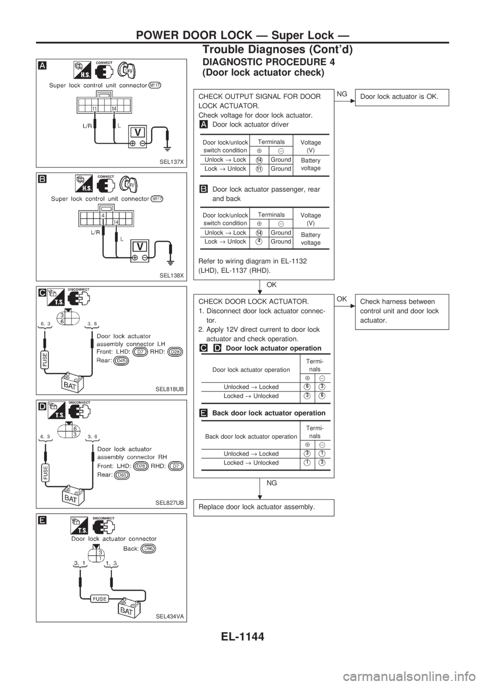
DIAGNOSTIC PROCEDURE 4
(Door lock actuator check)
CHECK OUTPUT SIGNAL FOR DOOR
LOCK ACTUATOR.
Check voltage for door lock actuator.
Door lock actuator driver
Door lock actuator passenger, rear
and back
Refer to wiring diagram in EL-1132
(LHD), EL-1137 (RHD).
OK
cNG
Door lock actuator is OK.
CHECK DOOR LOCK ACTUATOR.
1. Disconnect door lock actuator connec-
tor.
2. Apply 12V direct current to door lock
actuator and check operation.
Door lock actuator operation
Back door lock actuator operation
NG
cOK
Check harness between
control unit and door lock
actuator.
Replace door lock actuator assembly.
Door lock/unlock
switch conditionTerminals
Voltage
(V)
Å@
Unlock®Lock
V14Ground
Battery
voltage
Lock®Unlock
V11Ground
Door lock/unlock
switch conditionTerminals
Voltage
(V)
Å@
Unlock®Lock
V14Ground
Battery
voltage Lock®Unlock
V4Ground
Door lock actuator operationTermi-
nals
Å@
Unlocked®Locked
V6V3
Locked®UnlockedV3V6
Back door lock actuator operationTermi-
nals
Å@
Unlocked®Locked
V3V1
Locked®UnlockedV1V3
SEL137X
SEL138X
SEL818UB
SEL827UB
SEL434VA
.
.
POWER DOOR LOCK Ð Super Lock Ð
Trouble Diagnoses (Cont'd)
EL-1144
Page 655 of 1033
![NISSAN PATROL 2000 Electronic Repair Manual DIAGNOSTIC PROCEDURE 5
[Super lock actuator (in door lock actuator assembly)
check]
CHECK OUTPUT SIGNAL FOR SUPER
LOCK ACTUATOR.
Check voltage for super lock actuator.
Put the system in set condition NISSAN PATROL 2000 Electronic Repair Manual DIAGNOSTIC PROCEDURE 5
[Super lock actuator (in door lock actuator assembly)
check]
CHECK OUTPUT SIGNAL FOR SUPER
LOCK ACTUATOR.
Check voltage for super lock actuator.
Put the system in set condition](/img/5/57367/w960_57367-654.png)
DIAGNOSTIC PROCEDURE 5
[Super lock actuator (in door lock actuator assembly)
check]
CHECK OUTPUT SIGNAL FOR SUPER
LOCK ACTUATOR.
Check voltage for super lock actuator.
Put the system in set condition before
checking release signal.
Refer to wiring diagram in EL-1131
(LHD), EL-1136 (RHD).
OK
cNG
Super lock actuator is OK.
CHECK SUPER LOCK ACTUATOR.
1. Disconnect door lock actuator assem-
bly connector.
2. Set lever A in Lock position.
3. Apply 12V direct current to door lock
actuator assembly and check opera-
tion.
NG
cOK
Check harness between
control unit and door lock
actuator assembly.
Replace door lock actuator assembly.
Door key cylin-
der switch con-
ditionTerminals
Voltage
(V)
Å@
Lock (Set)
V6Ground
Approx. 12
Unlock
(Released)
V3Ground
Super lock
actuator opera-
tionTermi-
nalsConnection from
lever B to lever
A
Å@
Released®Set
V1V4Disconnect
Set®Released
V4V1Connect
SEL139X
SEL820UB
.
.
POWER DOOR LOCK Ð Super Lock Ð
Trouble Diagnoses (Cont'd)
EL-1145
Page 656 of 1033
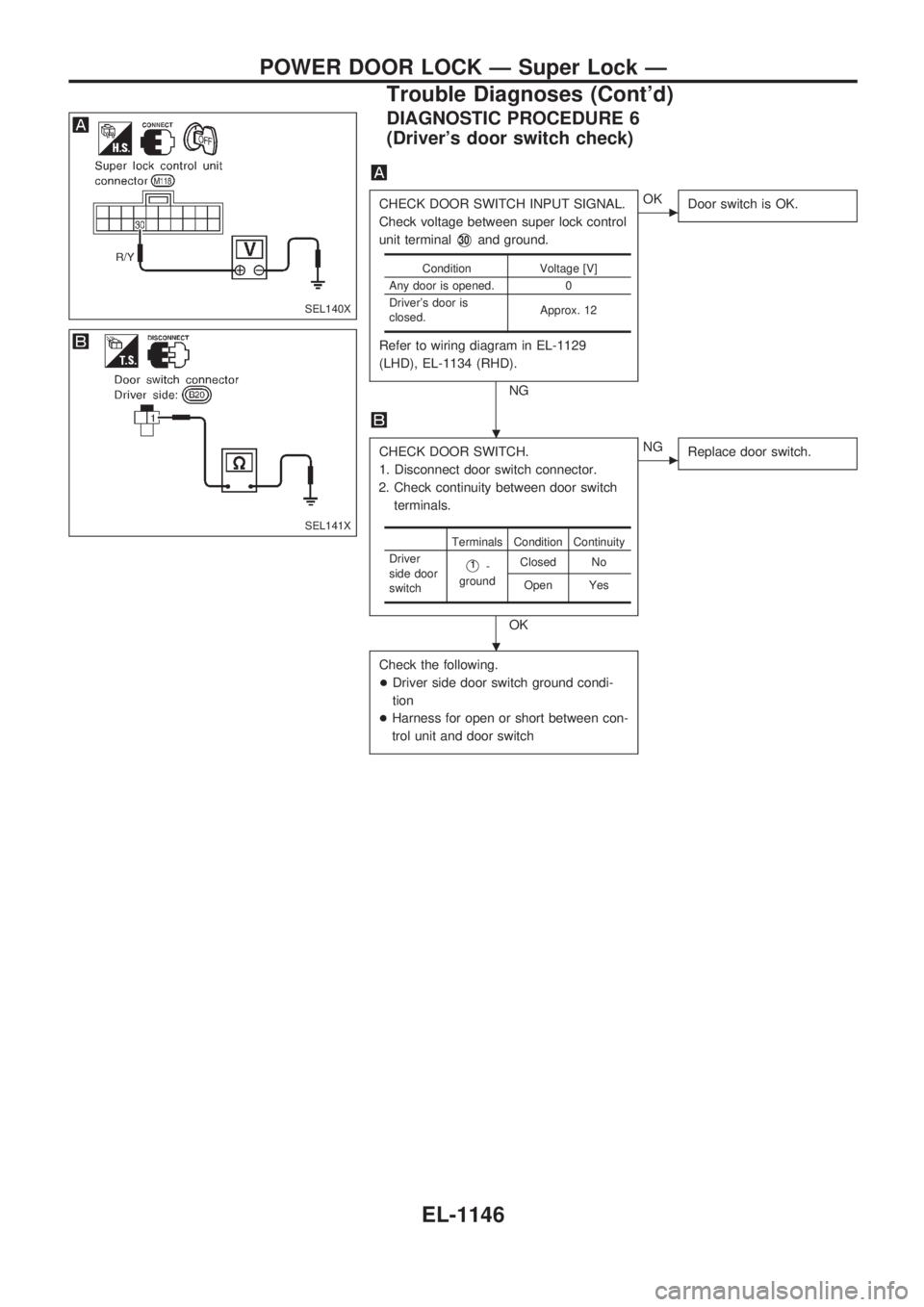
DIAGNOSTIC PROCEDURE 6
(Driver's door switch check)
CHECK DOOR SWITCH INPUT SIGNAL.
Check voltage between super lock control
unit terminal
V30and ground.
Refer to wiring diagram in EL-1129
(LHD), EL-1134 (RHD).
NG
cOK
Door switch is OK.
CHECK DOOR SWITCH.
1. Disconnect door switch connector.
2. Check continuity between door switch
terminals.
OK
cNG
Replace door switch.
Check the following.
+Driver side door switch ground condi-
tion
+Harness for open or short between con-
trol unit and door switch
Condition Voltage [V]
Any door is opened. 0
Driver's door is
closed.Approx. 12
Terminals Condition Continuity
Driver
side door
switch
V1-
groundClosed No
Open Yes
SEL140X
SEL141X
.
.
POWER DOOR LOCK Ð Super Lock Ð
Trouble Diagnoses (Cont'd)
EL-1146
Page 657 of 1033
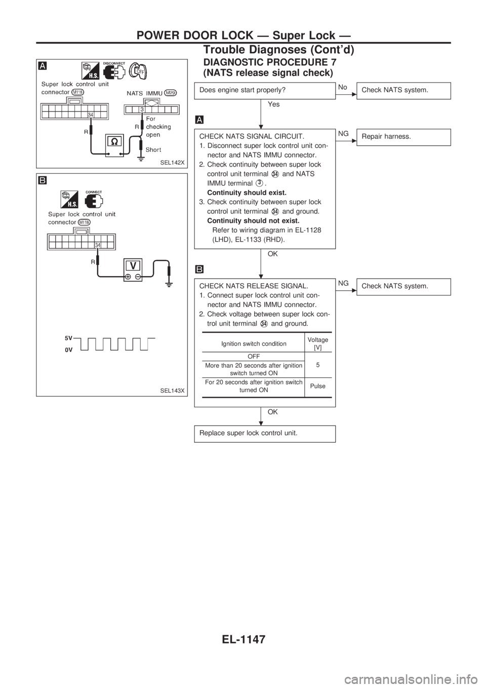
DIAGNOSTIC PROCEDURE 7
(NATS release signal check)
Does engine start properly?
Yes
cNo
Check NATS system.
CHECK NATS SIGNAL CIRCUIT.
1. Disconnect super lock control unit con-
nector and NATS IMMU connector.
2. Check continuity between super lock
control unit terminal
V34and NATS
IMMU terminal
V3.
Continuity should exist.
3. Check continuity between super lock
control unit terminal
V34and ground.
Continuity should not exist.
Refer to wiring diagram in EL-1128
(LHD), EL-1133 (RHD).
OK
cNG
Repair harness.
CHECK NATS RELEASE SIGNAL.
1. Connect super lock control unit con-
nector and NATS IMMU connector.
2. Check voltage between super lock con-
trol unit terminal
V34and ground.
OK
cNG
Check NATS system.
Replace super lock control unit.
Ignition switch conditionVoltage
[V]
OFF
5
More than 20 seconds after ignition
switch turned ON
For 20 seconds after ignition switch
turned ONPulse
SEL142X
SEL143X
.
.
.
POWER DOOR LOCK Ð Super Lock Ð
Trouble Diagnoses (Cont'd)
EL-1147
Page 658 of 1033
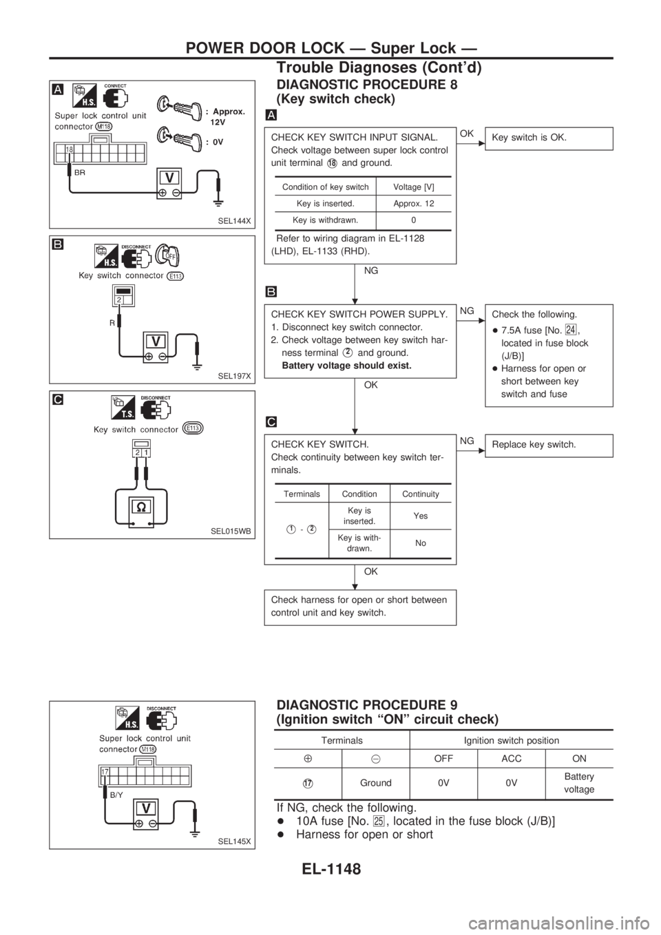
DIAGNOSTIC PROCEDURE 8
(Key switch check)
CHECK KEY SWITCH INPUT SIGNAL.
Check voltage between super lock control
unit terminal
V18and ground.
Refer to wiring diagram in EL-1128
(LHD), EL-1133 (RHD).
NG
cOK
Key switch is OK.
CHECK KEY SWITCH POWER SUPPLY.
1. Disconnect key switch connector.
2. Check voltage between key switch har-
ness terminal
V2and ground.
Battery voltage should exist.
OK
cNG
Check the following.
+7.5A fuse [No.
24,
located in fuse block
(J/B)]
+Harness for open or
short between key
switch and fuse
CHECK KEY SWITCH.
Check continuity between key switch ter-
minals.
OK
cNG
Replace key switch.
Check harness for open or short between
control unit and key switch.
Condition of key switch Voltage [V]
Key is inserted. Approx. 12
Key is withdrawn. 0
Terminals Condition Continuity
V1-V2
Key is
inserted.Yes
Key is with-
drawn.No
DIAGNOSTIC PROCEDURE 9
(Ignition switch ªONº circuit check)
Terminals Ignition switch position
Å@OFF ACC ON
V17Ground 0V 0VBattery
voltage
If NG, check the following.
+10A fuse [No.
25, located in the fuse block (J/B)]
+Harness for open or short
SEL144X
SEL197X
SEL015WB
SEL145X
.
.
.
POWER DOOR LOCK Ð Super Lock Ð
Trouble Diagnoses (Cont'd)
EL-1148
Page 659 of 1033
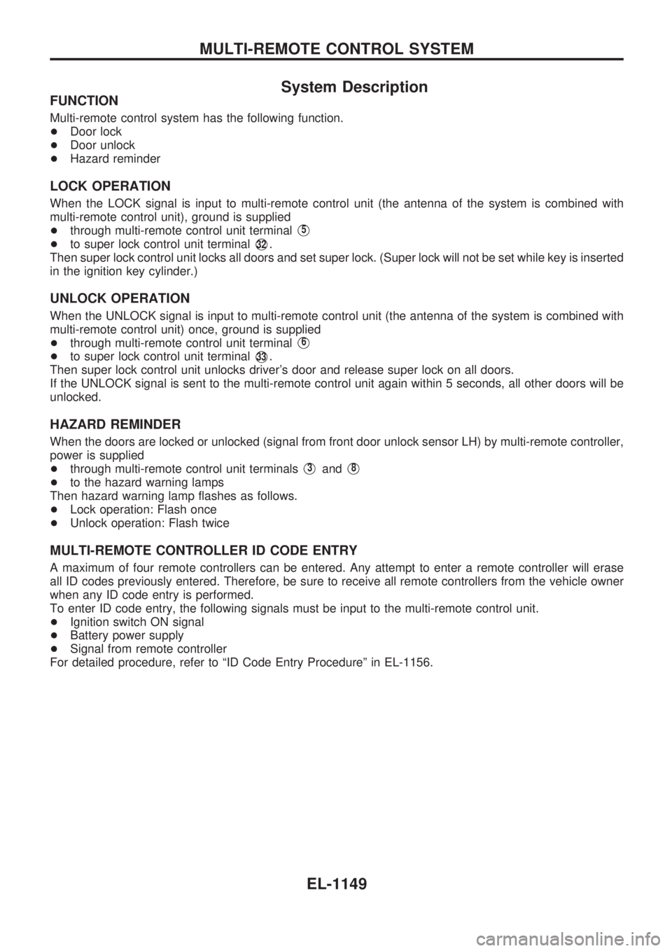
System Description
FUNCTION
Multi-remote control system has the following function.
+Door lock
+Door unlock
+Hazard reminder
LOCK OPERATION
When the LOCK signal is input to multi-remote control unit (the antenna of the system is combined with
multi-remote control unit), ground is supplied
+through multi-remote control unit terminal
V5
+to super lock control unit terminalV32.
Then super lock control unit locks all doors and set super lock. (Super lock will not be set while key is inserted
in the ignition key cylinder.)
UNLOCK OPERATION
When the UNLOCK signal is input to multi-remote control unit (the antenna of the system is combined with
multi-remote control unit) once, ground is supplied
+through multi-remote control unit terminal
V6
+to super lock control unit terminalV33.
Then super lock control unit unlocks driver's door and release super lock on all doors.
If the UNLOCK signal is sent to the multi-remote control unit again within 5 seconds, all other doors will be
unlocked.
HAZARD REMINDER
When the doors are locked or unlocked (signal from front door unlock sensor LH) by multi-remote controller,
power is supplied
+through multi-remote control unit terminals
V3andV8
+to the hazard warning lamps
Then hazard warning lamp flashes as follows.
+Lock operation: Flash once
+Unlock operation: Flash twice
MULTI-REMOTE CONTROLLER ID CODE ENTRY
A maximum of four remote controllers can be entered. Any attempt to enter a remote controller will erase
all ID codes previously entered. Therefore, be sure to receive all remote controllers from the vehicle owner
when any ID code entry is performed.
To enter ID code entry, the following signals must be input to the multi-remote control unit.
+Ignition switch ON signal
+Battery power supply
+Signal from remote controller
For detailed procedure, refer to ªID Code Entry Procedureº in EL-1156.
MULTI-REMOTE CONTROL SYSTEM
EL-1149
Page 660 of 1033
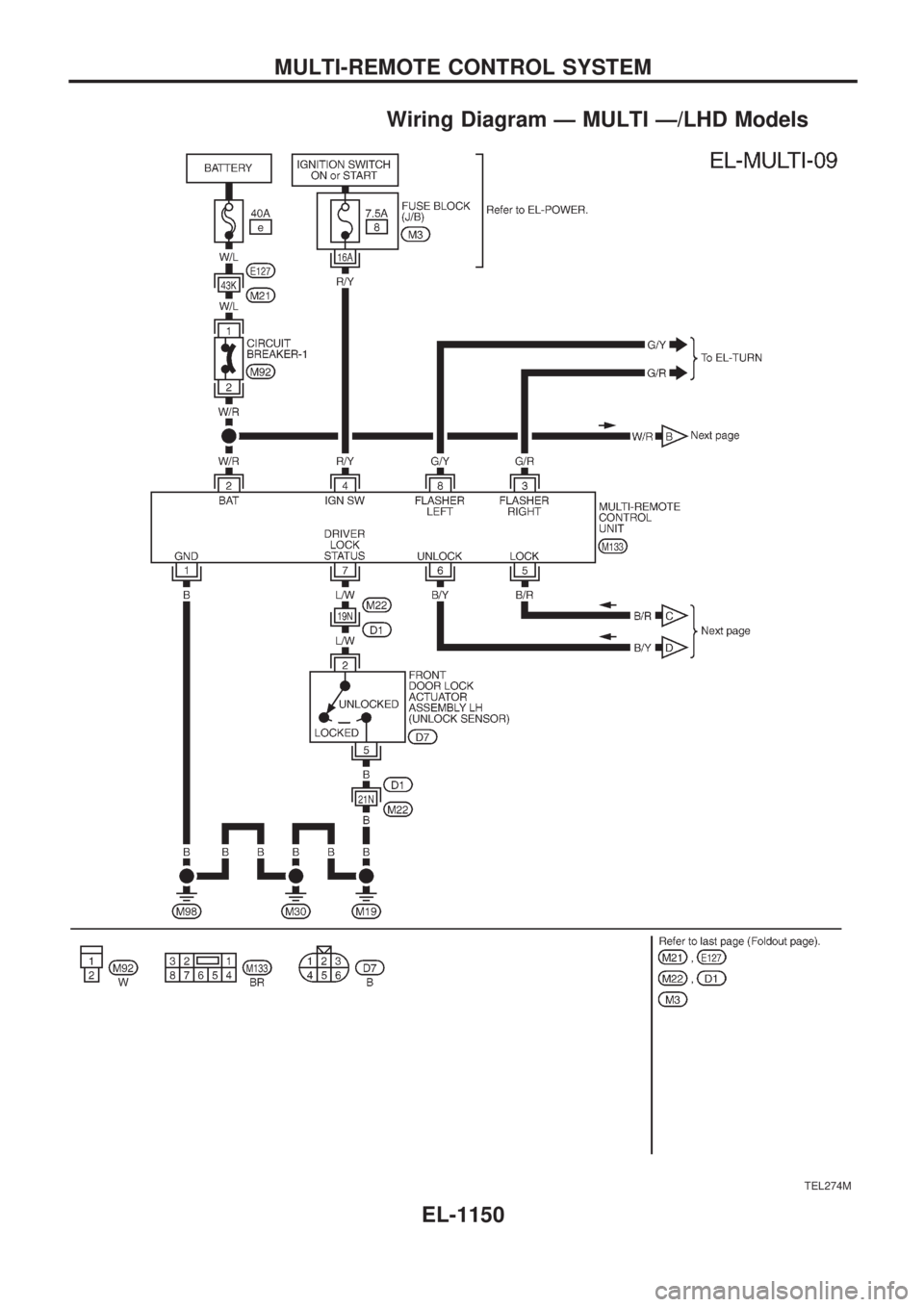
Wiring Diagram Ð MULTI Ð/LHD Models
TEL274M
MULTI-REMOTE CONTROL SYSTEM
EL-1150