NISSAN PICK-UP 1998 Repair Manual
PICK-UP 1998
NISSAN
NISSAN
https://www.carmanualsonline.info/img/5/57374/w960_57374-0.png
NISSAN PICK-UP 1998 Repair Manual
Trending: low beam, transmission fluid, height, run flat, radiator, battery location, diagram
Page 1131 of 1659
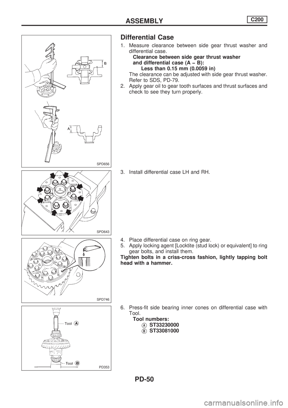
Differential Case
1. Measure clearance between side gear thrust washer and
differential case.
Clearance between side gear thrust washer
and differential case (A þ B):
Less than 0.15 mm (0.0059 in)
The clearance can be adjusted with side gear thrust washer.
Refer to SDS, PD-79.
2. Apply gear oil to gear tooth surfaces and thrust surfaces and
check to see they turn properly.
3. Install differential case LH and RH.
4. Place differential case on ring gear.
5. Apply locking agent [Locktite (stud lock) or equivalent] to ring
gear bolts, and install them.
Tighten bolts in a criss-cross fashion, lightly tapping bolt
head with a hammer.
6. Press-fit side bearing inner cones on differential case with
Tool.
Tool numbers:
VAST33230000
VBST33081000
SPD656
SPD643
SPD746
PD353
ASSEMBLYC200
PD-50
Page 1132 of 1659
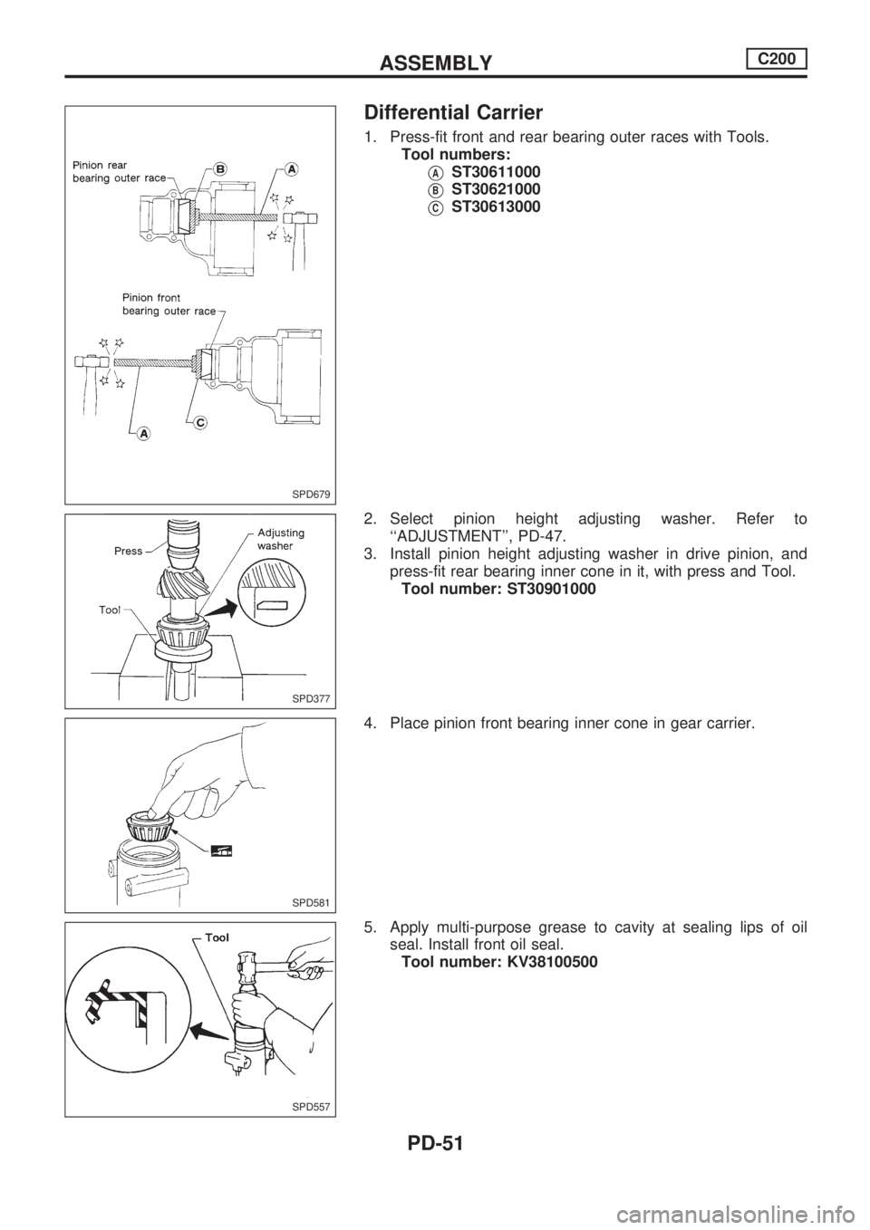
Differential Carrier
1. Press-fit front and rear bearing outer races with Tools.
Tool numbers:
VAST30611000
VBST30621000
VCST30613000
2. Select pinion height adjusting washer. Refer to
``ADJUSTMENT'', PD-47.
3. Install pinion height adjusting washer in drive pinion, and
press-fit rear bearing inner cone in it, with press and Tool.
Tool number: ST30901000
4. Place pinion front bearing inner cone in gear carrier.
5. Apply multi-purpose grease to cavity at sealing lips of oil
seal. Install front oil seal.
Tool number: KV38100500
SPD679
SPD377
SPD581
SPD557
ASSEMBLYC200
PD-51
Page 1133 of 1659
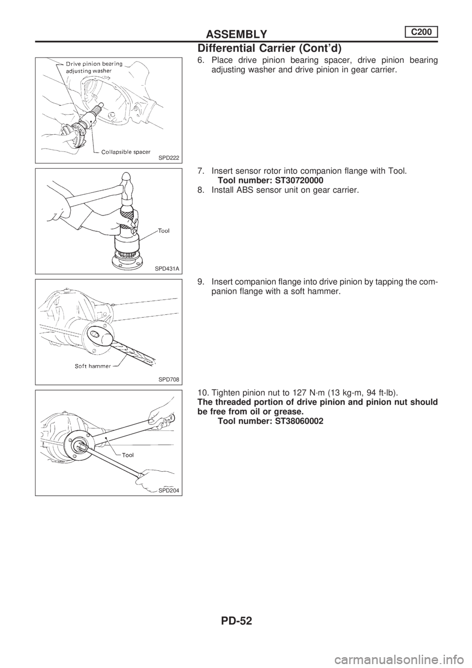
6. Place drive pinion bearing spacer, drive pinion bearing
adjusting washer and drive pinion in gear carrier.
7. Insert sensor rotor into companion flange with Tool.
Tool number: ST30720000
8. Install ABS sensor unit on gear carrier.
9. Insert companion flange into drive pinion by tapping the com-
panion flange with a soft hammer.
10. Tighten pinion nut to 127 N´m (13 kg-m, 94 ft-lb).
The threaded portion of drive pinion and pinion nut should
be free from oil or grease.
Tool number: ST38060002
SPD222
SPD431A
SPD708
SPD204.SPD204
ASSEMBLYC200
Differential Carrier (Cont'd)
PD-52
Page 1134 of 1659
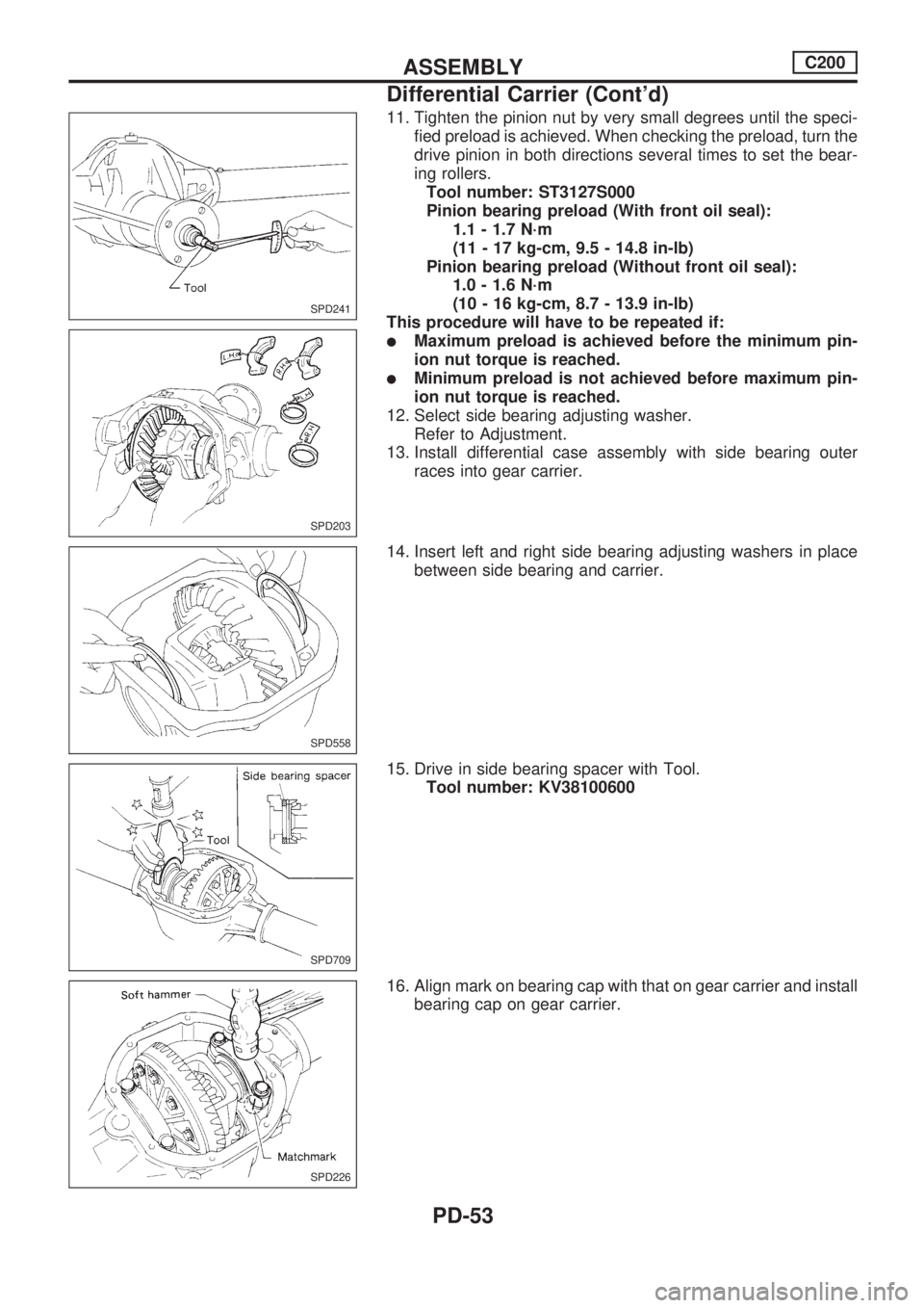
11. Tighten the pinion nut by very small degrees until the speci-
fied preload is achieved. When checking the preload, turn the
drive pinion in both directions several times to set the bear-
ing rollers.
Tool number: ST3127S000
Pinion bearing preload (With front oil seal):
1.1 - 1.7 N´m
(11 - 17 kg-cm, 9.5 - 14.8 in-lb)
Pinion bearing preload (Without front oil seal):
1.0 - 1.6 N´m
(10 - 16 kg-cm, 8.7 - 13.9 in-lb)
This procedure will have to be repeated if:
lMaximum preload is achieved before the minimum pin-
ion nut torque is reached.
lMinimum preload is not achieved before maximum pin-
ion nut torque is reached.
12. Select side bearing adjusting washer.
Refer to Adjustment.
13. Install differential case assembly with side bearing outer
races into gear carrier.
14. Insert left and right side bearing adjusting washers in place
between side bearing and carrier.
15. Drive in side bearing spacer with Tool.
Tool number: KV38100600
16. Align mark on bearing cap with that on gear carrier and install
bearing cap on gear carrier.
SPD241
SPD203
SPD558
SPD709
SPD226
ASSEMBLYC200
Differential Carrier (Cont'd)
PD-53
Page 1135 of 1659
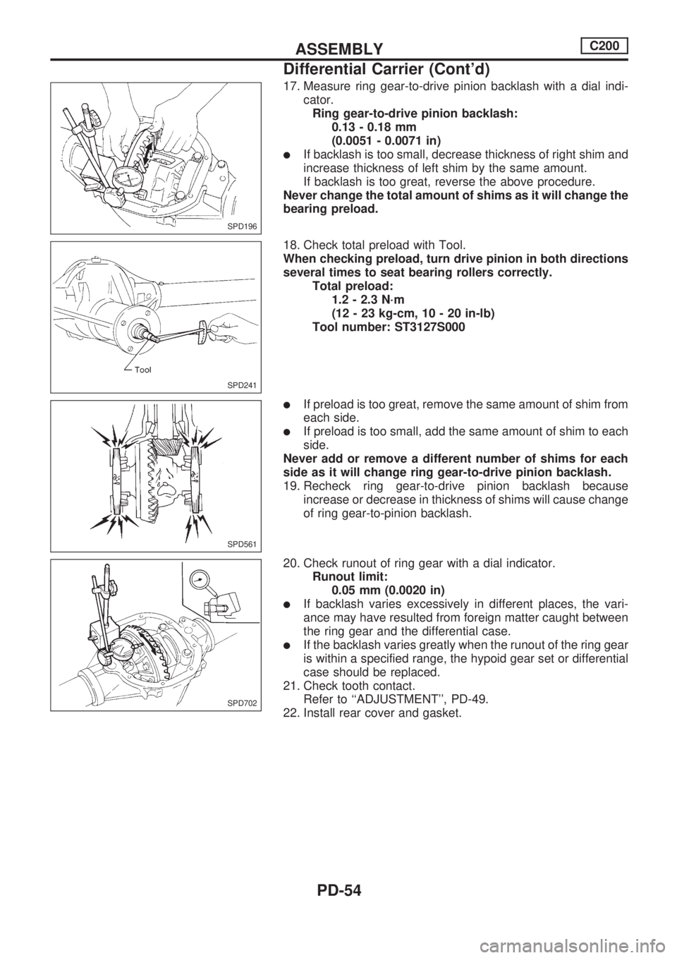
17. Measure ring gear-to-drive pinion backlash with a dial indi-
cator.
Ring gear-to-drive pinion backlash:
0.13 - 0.18 mm
(0.0051 - 0.0071 in)
lIf backlash is too small, decrease thickness of right shim and
increase thickness of left shim by the same amount.
If backlash is too great, reverse the above procedure.
Never change the total amount of shims as it will change the
bearing preload.
18. Check total preload with Tool.
When checking preload, turn drive pinion in both directions
several times to seat bearing rollers correctly.
Total preload:
1.2 - 2.3 N´m
(12 - 23 kg-cm, 10 - 20 in-lb)
Tool number: ST3127S000
lIf preload is too great, remove the same amount of shim from
each side.
lIf preload is too small, add the same amount of shim to each
side.
Never add or remove a different number of shims for each
side as it will change ring gear-to-drive pinion backlash.
19. Recheck ring gear-to-drive pinion backlash because
increase or decrease in thickness of shims will cause change
of ring gear-to-pinion backlash.
20. Check runout of ring gear with a dial indicator.
Runout limit:
0.05 mm (0.0020 in)
lIf backlash varies excessively in different places, the vari-
ance may have resulted from foreign matter caught between
the ring gear and the differential case.
lIf the backlash varies greatly when the runout of the ring gear
is within a specified range, the hypoid gear set or differential
case should be replaced.
21. Check tooth contact.
Refer to ``ADJUSTMENT'', PD-49.
22. Install rear cover and gasket.
SPD196
SPD241
SPD561
SPD702
ASSEMBLYC200
Differential Carrier (Cont'd)
PD-54
Page 1136 of 1659
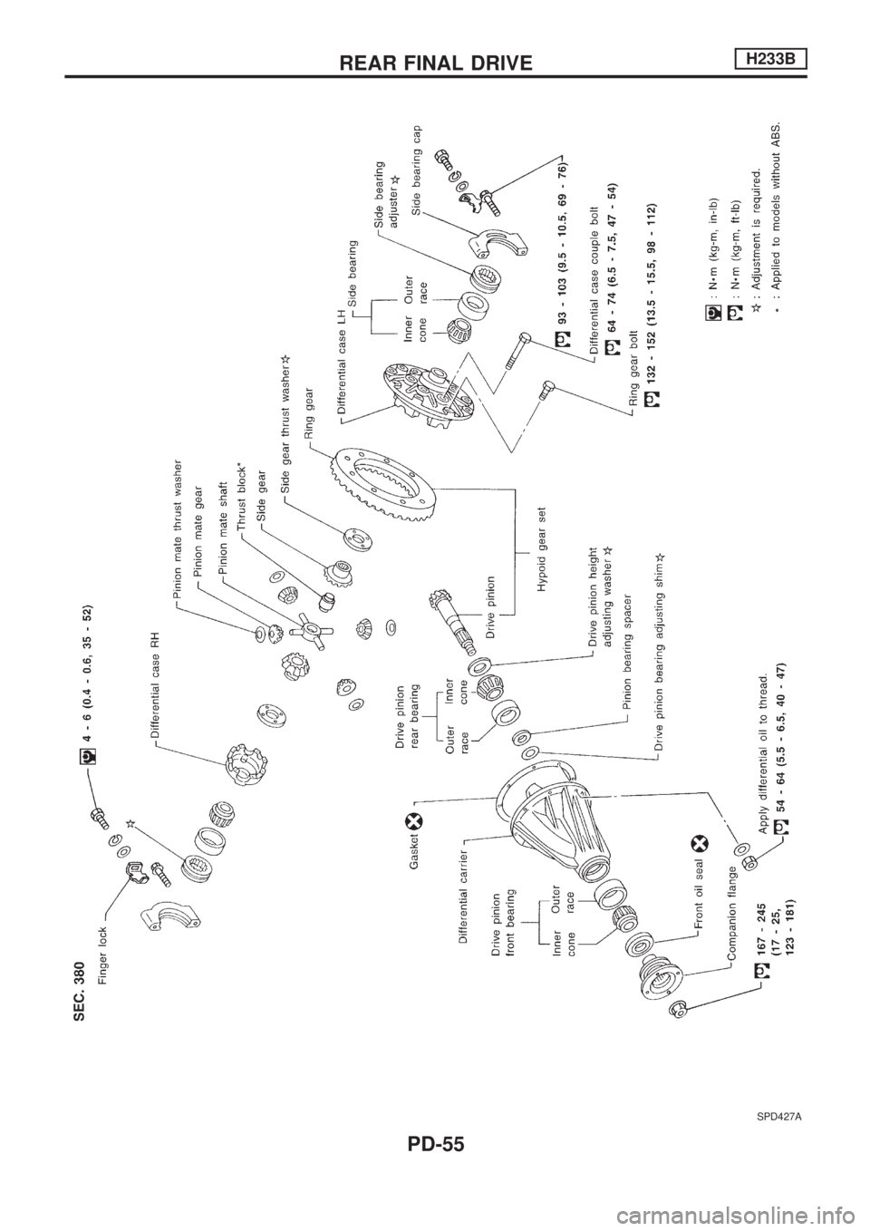
SPD427A
REAR FINAL DRIVEH233B
PD-55
Page 1137 of 1659
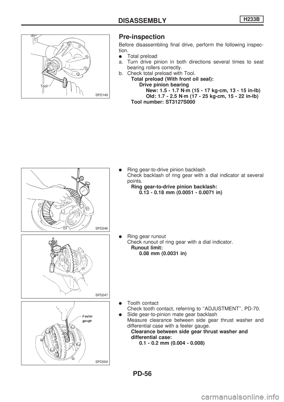
Pre-inspection
Before disassembling final drive, perform the following inspec-
tion.
lTotal preload
a. Turn drive pinion in both directions several times to seat
bearing rollers correctly.
b. Check total preload with Tool.
Total preload (With front oil seal):
Drive pinion bearing
New: 1.5 - 1.7 N´m (15 - 17 kg-cm, 13 - 15 in-lb)
Old: 1.7 - 2.5 N´m (17 - 25 kg-cm, 15 - 22 in-lb)
Tool number: ST3127S000
lRing gear-to-drive pinion backlash
Check backlash of ring gear with a dial indicator at several
points.
Ring gear-to-drive pinion backlash:
0.13 - 0.18 mm (0.0051 - 0.0071 in)
lRing gear runout
Check runout of ring gear with a dial indicator.
Runout limit:
0.08 mm (0.0031 in)
lTooth contact
Check tooth contact, referring to ``ADJUSTMENT'', PD-70.
lSide gear-to-pinion mate gear backlash
Measure clearance between side gear thrust washer and
differential case with a feeler gauge.
Clearance between side gear thrust washer and
differential case:
0.1 - 0.2 mm (0.004 - 0.008)
SPD149
SPD246
SPD247
SPD004
DISASSEMBLYH233B
PD-56
Page 1138 of 1659
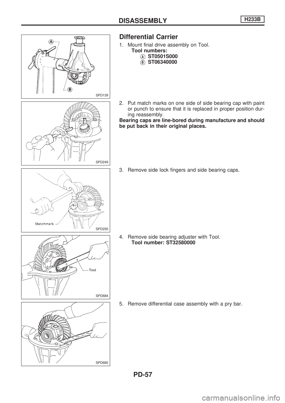
Differential Carrier
1. Mount final drive assembly on Tool.
Tool numbers:
VAST0501S000
VBST06340000
2. Put match marks on one side of side bearing cap with paint
or punch to ensure that it is replaced in proper position dur-
ing reassembly.
Bearing caps are line-bored during manufacture and should
be put back in their original places.
3. Remove side lock fingers and side bearing caps.
4. Remove side bearing adjuster with Tool.
Tool number: ST32580000
5. Remove differential case assembly with a pry bar.
SPD139
SPD249
SPD250
SPD684
SPD685
DISASSEMBLYH233B
PD-57
Page 1139 of 1659
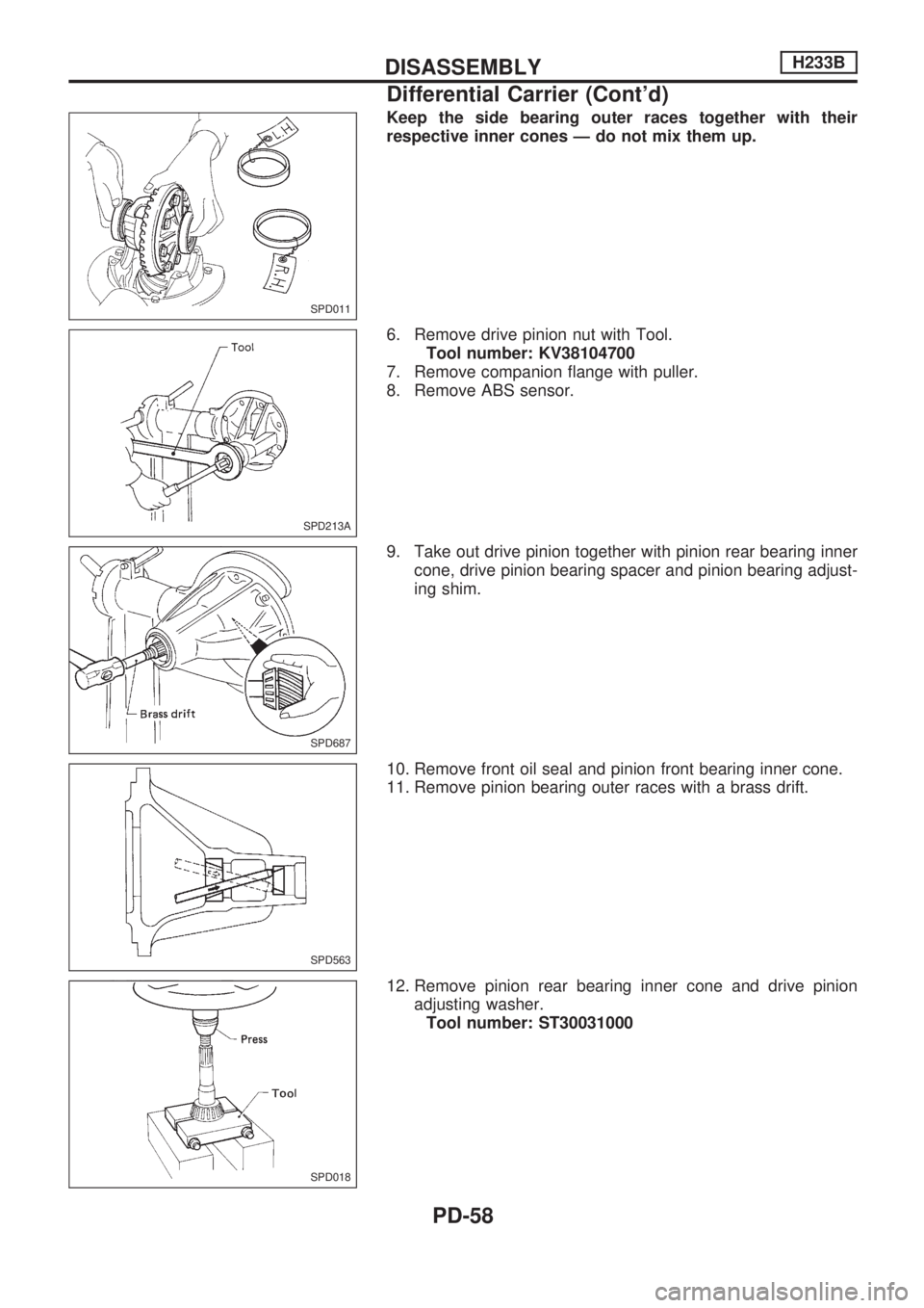
Keep the side bearing outer races together with their
respective inner cones Ð do not mix them up.
6. Remove drive pinion nut with Tool.
Tool number: KV38104700
7. Remove companion flange with puller.
8. Remove ABS sensor.
9. Take out drive pinion together with pinion rear bearing inner
cone, drive pinion bearing spacer and pinion bearing adjust-
ing shim.
10. Remove front oil seal and pinion front bearing inner cone.
11. Remove pinion bearing outer races with a brass drift.
12. Remove pinion rear bearing inner cone and drive pinion
adjusting washer.
Tool number: ST30031000
SPD011
SPD213A
SPD687
SPD563
SPD018
DISASSEMBLYH233B
Differential Carrier (Cont'd)
PD-58
Page 1140 of 1659
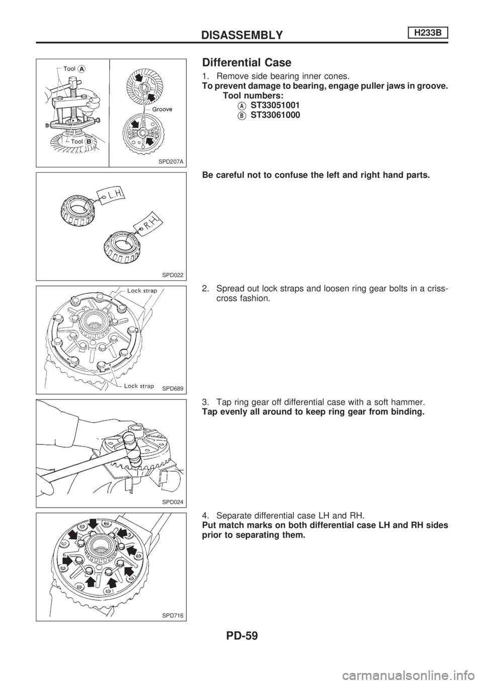
Differential Case
1. Remove side bearing inner cones.
To prevent damage to bearing, engage puller jaws in groove.
Tool numbers:
VAST33051001
VBST33061000
Be careful not to confuse the left and right hand parts.
2. Spread out lock straps and loosen ring gear bolts in a criss-
cross fashion.
3. Tap ring gear off differential case with a soft hammer.
Tap evenly all around to keep ring gear from binding.
4. Separate differential case LH and RH.
Put match marks on both differential case LH and RH sides
prior to separating them.
SPD207A
SPD022
SPD689
SPD024
SPD716
DISASSEMBLYH233B
PD-59
Trending: check transmission fluid, coolant reservoir, spark plugs, instrument panel, air condition, low oil pressure, overheating
