NISSAN PICK-UP 1998 Repair Manual
Manufacturer: NISSAN, Model Year: 1998, Model line: PICK-UP, Model: NISSAN PICK-UP 1998Pages: 1659, PDF Size: 53.39 MB
Page 1161 of 1659
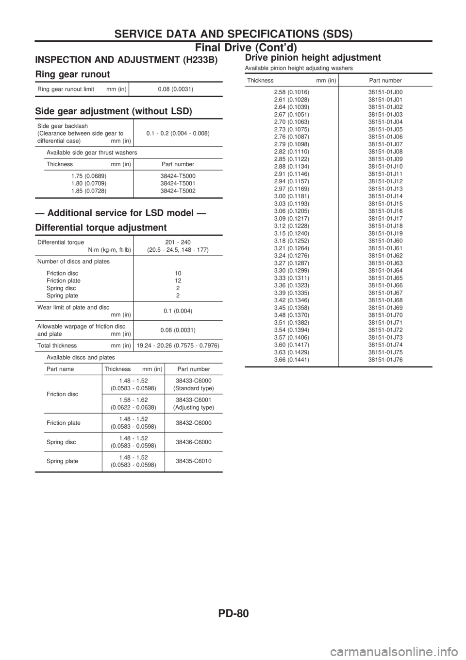
INSPECTION AND ADJUSTMENT (H233B)
Ring gear runout
Ring gear runout limit mm (in) 0.08 (0.0031)
Side gear adjustment (without LSD)
Side gear backlash
(Clearance between side gear to
differential case) mm (in)0.1 - 0.2 (0.004 - 0.008)
Available side gear thrust washers
Thickness mm (in) Part number
1.75 (0.0689)
1.80 (0.0709)
1.85 (0.0728)38424-T5000
38424-T5001
38424-T5002
Ð Additional service for LSD model Ð
Differential torque adjustment
Differential torque
N´m (kg-m, ft-lb)201 - 240
(20.5 - 24.5, 148 - 177)
Number of discs and plates
Friction disc
Friction plate
Spring disc
Spring plate10
12
2
2
Wear limit of plate and disc
mm (in)0.1 (0.004)
Allowable warpage of friction disc
and plate mm (in)0.08 (0.0031)
Total thickness mm (in) 19.24 - 20.26 (0.7575 - 0.7976)
Available discs and plates
Part name Thickness mm (in) Part number
Friction disc1.48 - 1.52
(0.0583 - 0.0598)38433-C6000
(Standard type)
1.58 - 1.62
(0.0622 - 0.0638)38433-C6001
(Adjusting type)
Friction plate1.48 - 1.52
(0.0583 - 0.0598)38432-C6000
Spring disc1.48 - 1.52
(0.0583 - 0.0598)38436-C6000
Spring plate1.48 - 1.52
(0.0583 - 0.0598)38435-C6010
Drive pinion height adjustment
Available pinion height adjusting washers
Thickness mm (in) Part number
2.58 (0.1016)
2.61 (0.1028)
2.64 (0.1039)
2.67 (0.1051)
2.70 (0.1063)
2.73 (0.1075)
2.76 (0.1087)
2.79 (0.1098)
2.82 (0.1110)
2.85 (0.1122)
2.88 (0.1134)
2.91 (0.1146)
2.94 (0.1157)
2.97 (0.1169)
3.00 (0.1181)
3.03 (0.1193)
3.06 (0.1205)
3.09 (0.1217)
3.12 (0.1228)
3.15 (0.1240)
3.18 (0.1252)
3.21 (0.1264)
3.24 (0.1276)
3.27 (0.1287)
3.30 (0.1299)
3.33 (0.1311)
3.36 (0.1323)
3.39 (0.1335)
3.42 (0.1346)
3.45 (0.1358)
3.48 (0.1370)
3.51 (0.1382)
3.54 (0.1394)
3.57 (0.1406)
3.60 (0.1417)
3.63 (0.1429)
3.66 (0.1441)38151-01J00
38151-01J01
38151-01J02
38151-01J03
38151-01J04
38151-01J05
38151-01J06
38151-01J07
38151-01J08
38151-01J09
38151-01J10
38151-01J11
38151-01J12
38151-01J13
38151-01J14
38151-01J15
38151-01J16
38151-01J17
38151-01J18
38151-01J19
38151-01J60
38151-01J61
38151-01J62
38151-01J63
38151-01J64
38151-01J65
38151-01J66
38151-01J67
38151-01J68
38151-01J69
38151-01J70
38151-01J71
38151-01J72
38151-01J73
38151-01J74
38151-01J75
38151-01J76
SERVICE DATA AND SPECIFICATIONS (SDS)
Final Drive (Cont'd)
PD-80
Page 1162 of 1659
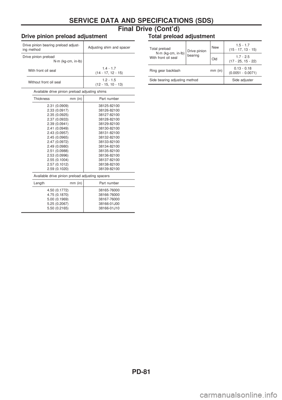
Drive pinion preload adjustment
Drive pinion bearing preload adjust-
ing methodAdjusting shim and spacer
Drive pinion preload
N´m (kg-cm, in-lb)
With front oil seal1.4 - 1.7
(14 - 17, 12 - 15)
Without front oil seal1.2 - 1.5
(12 - 15, 10 - 13)
Available drive pinion preload adjusting shims
Thickness mm (in) Part number
2.31 (0.0909)
2.33 (0.0917)
2.35 (0.0925)
2.37 (0.0933)
2.39 (0.0941)
2.41 (0.0949)
2.43 (0.0957)
2.45 (0.0965)
2.47 (0.0972)
2.49 (0.0980)
2.51 (0.0988)
2.53 (0.0996)
2.55 (0.1004)
2.57 (0.1012)
2.59 (0.1020)38125-82100
38126-82100
38127-82100
38128-82100
38129-82100
38130-82100
38131-82100
38132-82100
38133-82100
38134-82100
38135-82100
38136-82100
38137-82100
38138-82100
38139-82100
Available drive pinion preload adjusting spacers
Length mm (in) Part number
4.50 (0.1772)
4.75 (0.1870)
5.00 (0.1969)
5.25 (0.2067)
5.50 (0.2165)38165-76000
38166-76000
38167-76000
38166-01J00
38166-01J10
Total preload adjustment
Total preload
N´m (kg-cm, in-lb)
With front oil sealDrive pinion
bearingNew1.5 - 1.7
(15 - 17, 13 - 15)
Old1.7 - 2.5
(17 - 25, 15 - 22)
Ring gear backlash mm (in)0.13 - 0.18
(0.0051 - 0.0071)
Side bearing adjusting method Side adjuster
SERVICE DATA AND SPECIFICATIONS (SDS)
Final Drive (Cont'd)
PD-81
Page 1163 of 1659
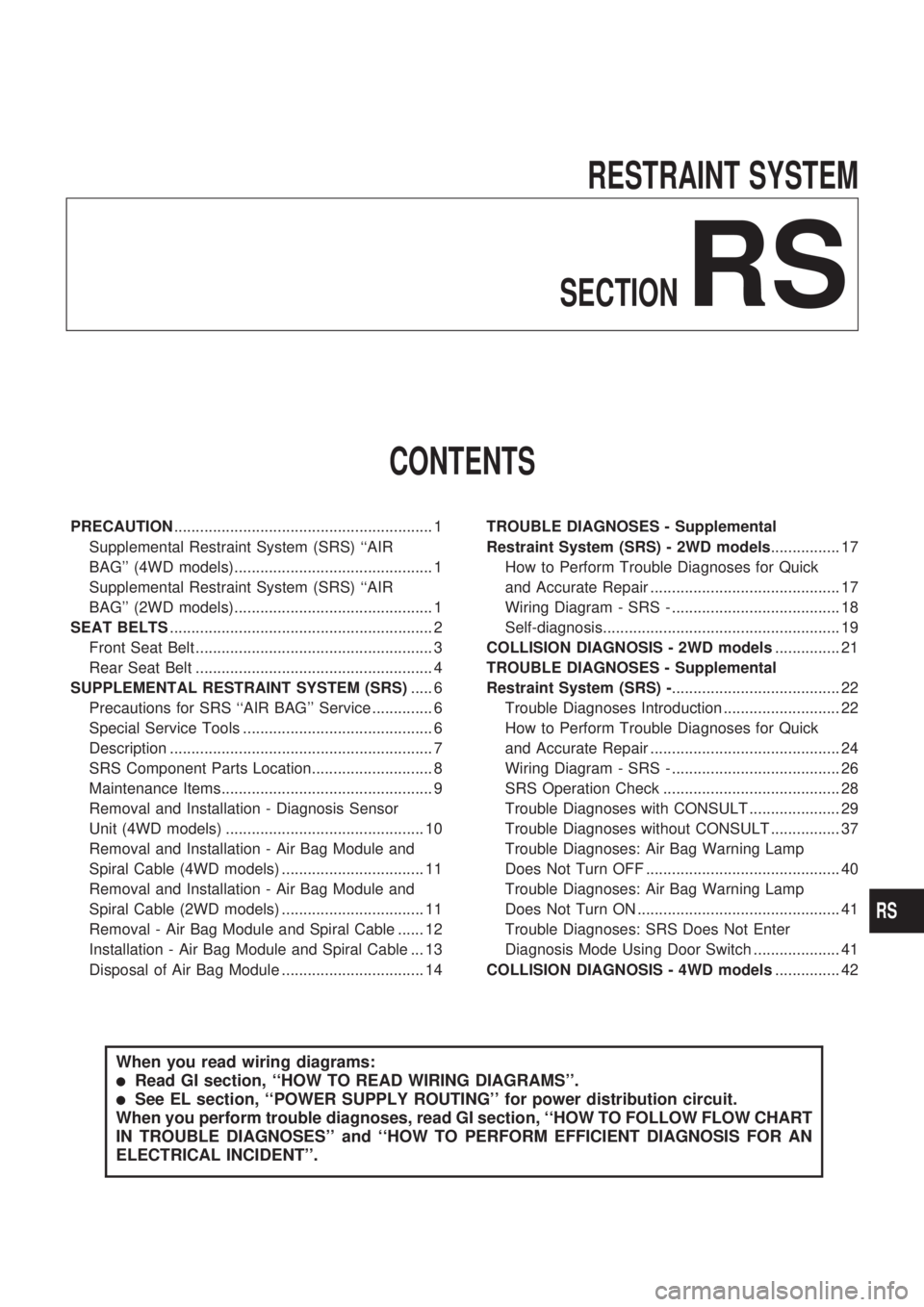
RESTRAINT SYSTEM
SECTION
RS
CONTENTS
PRECAUTION............................................................ 1
Supplemental Restraint System (SRS) ``AIR
BAG'' (4WD models).............................................. 1
Supplemental Restraint System (SRS) ``AIR
BAG'' (2WD models).............................................. 1
SEAT BELTS............................................................. 2
Front Seat Belt ....................................................... 3
Rear Seat Belt ....................................................... 4
SUPPLEMENTAL RESTRAINT SYSTEM (SRS)..... 6
Precautions for SRS ``AIR BAG'' Service .............. 6
Special Service Tools ............................................ 6
Description ............................................................. 7
SRS Component Parts Location............................ 8
Maintenance Items................................................. 9
Removal and Installation - Diagnosis Sensor
Unit (4WD models) .............................................. 10
Removal and Installation - Air Bag Module and
Spiral Cable (4WD models) ................................. 11
Removal and Installation - Air Bag Module and
Spiral Cable (2WD models) ................................. 11
Removal - Air Bag Module and Spiral Cable ...... 12
Installation - Air Bag Module and Spiral Cable ... 13
Disposal of Air Bag Module ................................. 14TROUBLE DIAGNOSES - Supplemental
Restraint System (SRS) - 2WD models................ 17
How to Perform Trouble Diagnoses for Quick
and Accurate Repair ............................................ 17
Wiring Diagram - SRS - ....................................... 18
Self-diagnosis....................................................... 19
COLLISION DIAGNOSIS - 2WD models............... 21
TROUBLE DIAGNOSES - Supplemental
Restraint System (SRS) -....................................... 22
Trouble Diagnoses Introduction ........................... 22
How to Perform Trouble Diagnoses for Quick
and Accurate Repair ............................................ 24
Wiring Diagram - SRS - ....................................... 26
SRS Operation Check ......................................... 28
Trouble Diagnoses with CONSULT ..................... 29
Trouble Diagnoses without CONSULT ................ 37
Trouble Diagnoses: Air Bag Warning Lamp
Does Not Turn OFF ............................................. 40
Trouble Diagnoses: Air Bag Warning Lamp
Does Not Turn ON ............................................... 41
Trouble Diagnoses: SRS Does Not Enter
Diagnosis Mode Using Door Switch .................... 41
COLLISION DIAGNOSIS - 4WD models............... 42
When you read wiring diagrams:
lRead GI section, ``HOW TO READ WIRING DIAGRAMS''.
lSee EL section, ``POWER SUPPLY ROUTING'' for power distribution circuit.
When you perform trouble diagnoses, read GI section, ``HOW TO FOLLOW FLOW CHART
IN TROUBLE DIAGNOSES'' and ``HOW TO PERFORM EFFICIENT DIAGNOSIS FOR AN
ELECTRICAL INCIDENT''.
RS
Page 1164 of 1659
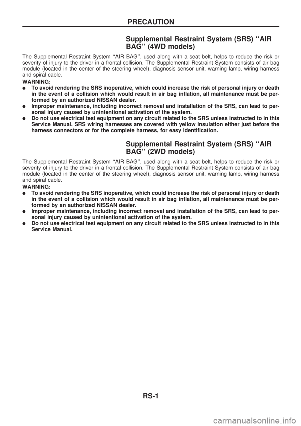
Supplemental Restraint System (SRS) ``AIR
BAG'' (4WD models)
The Supplemental Restraint System ``AIR BAG'', used along with a seat belt, helps to reduce the risk or
severity of injury to the driver in a frontal collision. The Supplemental Restraint System consists of air bag
module (located in the center of the steering wheel), diagnosis sensor unit, warning lamp, wiring harness
and spiral cable.
WARNING:
lTo avoid rendering the SRS inoperative, which could increase the risk of personal injury or death
in the event of a collision which would result in air bag inflation, all maintenance must be per-
formed by an authorized NISSAN dealer.
lImproper maintenance, including incorrect removal and installation of the SRS, can lead to per-
sonal injury caused by unintentional activation of the system.
lDo not use electrical test equipment on any circuit related to the SRS unless instructed to in this
Service Manual. SRS wiring harnesses are covered with yellow insulation either just before the
harness connectors or for the complete harness, for easy identification.
Supplemental Restraint System (SRS) ``AIR
BAG'' (2WD models)
The Supplemental Restraint System ``AIR BAG'', used along with a seat belt, helps to reduce the risk or
severity of injury to the driver in a frontal collision. The Supplemental Restraint System consists of air bag
module (located in the center of the steering wheel), diagnosis sensor unit, warning lamp, wiring harness
and spiral cable.
WARNING:
lTo avoid rendering the SRS inoperative, which could increase the risk of personal injury or death
in the event of a collision which would result in air bag inflation, all maintenance must be per-
formed by an authorized NISSAN dealer.
lImproper maintenance, including incorrect removal and installation of the SRS, can lead to per-
sonal injury caused by unintentional activation of the system.
lDo not use electrical test equipment on any circuit related to the SRS unless instructed to in this
Service Manual.
PRECAUTION
RS-1
Page 1165 of 1659
CAUTION:
lDo not disassemble buckle or seat belt assembly.
lReplace anchor bolts if they are deformed or worn out.
lNever oil tongue and buckle.
lIf any component of seat belt assembly is questionable, do not repair. Replace the whole seat
belt assembly.
lIf webbing is cut, frayed, or damaged, replace seat belt assembly.
lWhen replacing seat belt assembly, use a genuine seat belt assembly.
lAfter any collision, inspect all seat belt assemblies, including retractors and other attached
hardwares.
SEAT BELTS
RS-2
Page 1166 of 1659
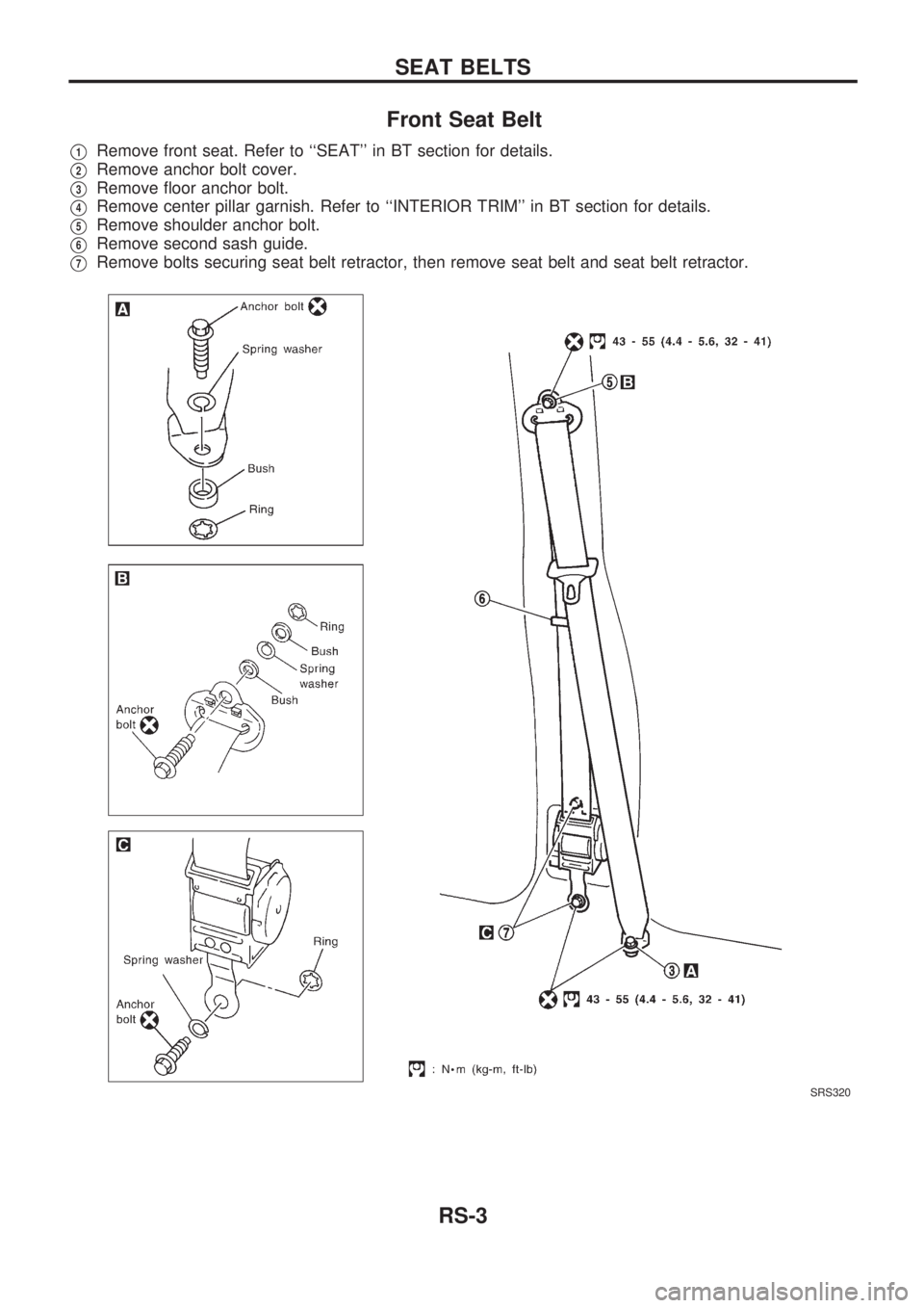
Front Seat Belt
V1Remove front seat. Refer to ``SEAT'' in BT section for details.
V2Remove anchor bolt cover.
V3Remove floor anchor bolt.
V4Remove center pillar garnish. Refer to ``INTERIOR TRIM'' in BT section for details.
V5Remove shoulder anchor bolt.
V6Remove second sash guide.
V7Remove bolts securing seat belt retractor, then remove seat belt and seat belt retractor.
SRS320
SEAT BELTS
RS-3
Page 1167 of 1659
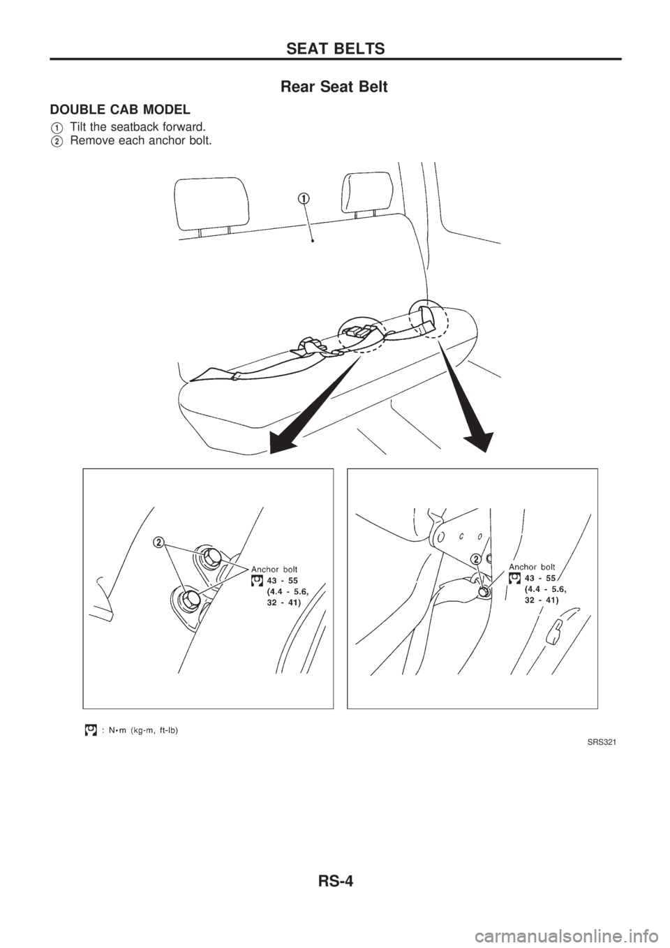
Rear Seat Belt
DOUBLE CAB MODEL
V1Tilt the seatback forward.
V2Remove each anchor bolt.
SRS321
SEAT BELTS
RS-4
Page 1168 of 1659
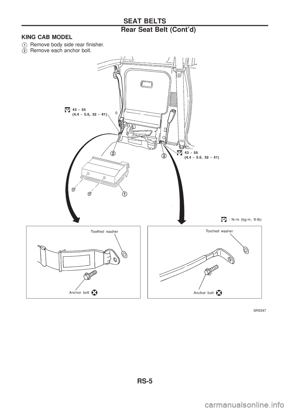
KING CAB MODEL
V1Remove body side rear finisher.
V2Remove each anchor bolt.
SRS547
SEAT BELTS
Rear Seat Belt (Cont'd)
RS-5
Page 1169 of 1659
Precautions for SRS ``AIR BAG'' Service
lDo not use a circuit tester to check SRS circuits unless instructed to in this Service Manual.
lBefore servicing the SRS, turn ignition switch ``OFF'', disconnect both battery cables and wait for at least
3 minutes.
For approximately 3 minutes after the cables are removed, it is still possible for the air bag to deploy.
Therefore, do not work on any SRS connectors or wires until at least 3 minutes have passed.
lFor 2WD models, do not separate diagnosis sensor unit from steering wheel.
lFor 4WD models, diagnosis sensor unit must always be installed with their arrow marks ``S'' pointing
towards the front of the vehicle for proper operation. Also check diagnosis sensor unit for cracks,
deformities or rust before installation and replace as required.
lThe spiral cable must be aligned with the neutral position since its rotations are limited. Do not attempt
to turn steering wheel or column after removal of steering gear.
lHandle air bag module carefully. Always place it with the pad side facing upward.
lConduct self-diagnosis to check entire SRS for proper function after replacing any components.
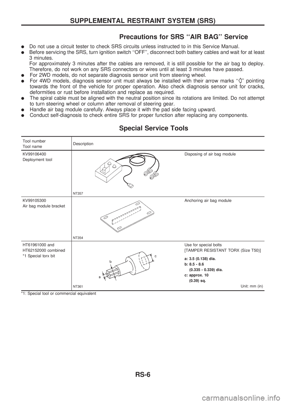
Special Service Tools
Tool number
Tool nameDescription
KV99106400
Deployment tool
NT357
Disposing of air bag module
KV99105300
Air bag module bracket
NT354
Anchoring air bag module
HT61961000 and
HT62152000 combined
*1 Special torx bit
NT361
Use for special bolts
[TAMPER RESISTANT TORX (Size T50)]
a: 3.5 (0.138) dia.
b: 8.5 - 8.6
(0.335 - 0.339) dia.
c: approx. 10
(0.39) sq.
Unit: mm (in)
*1: Special tool or commercial equivalent
SUPPLEMENTAL RESTRAINT SYSTEM (SRS)
RS-6
Page 1170 of 1659
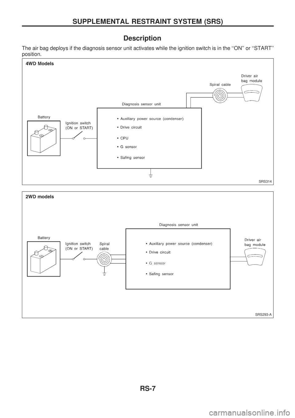
Description
The air bag deploys if the diagnosis sensor unit activates while the ignition switch is in the ``ON'' or ``START''
position.
SRS314
SRS293-A
SUPPLEMENTAL RESTRAINT SYSTEM (SRS)
RS-7