NISSAN PICK-UP 1998 Repair Manual
PICK-UP 1998
NISSAN
NISSAN
https://www.carmanualsonline.info/img/5/57374/w960_57374-0.png
NISSAN PICK-UP 1998 Repair Manual
Trending: octane, load capacity, 4WD, coolant capacity, sensor, wheel torque, towing
Page 1091 of 1659
JOURNAL
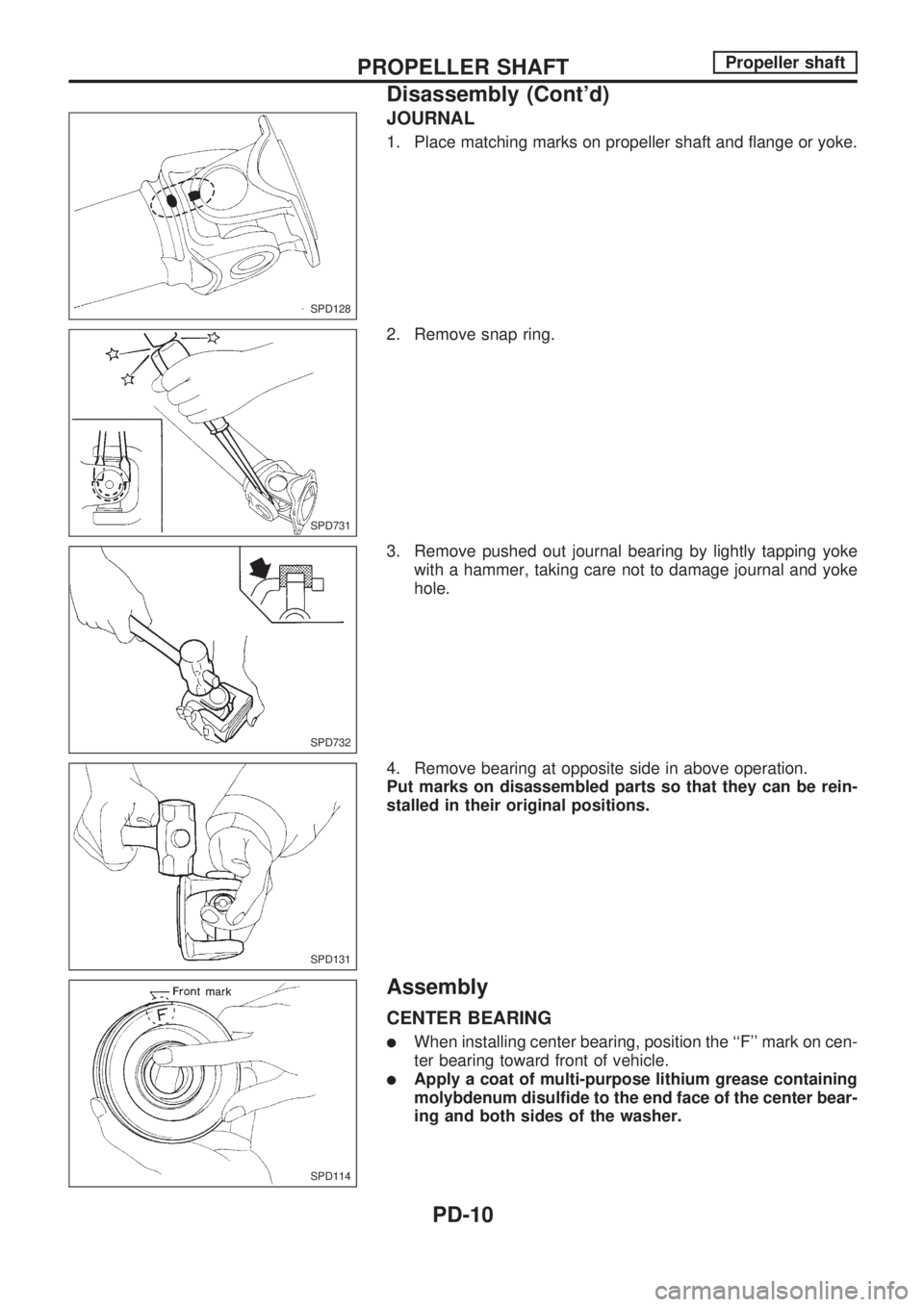
1. Place matching marks on propeller shaft and flange or yoke.
2. Remove snap ring.
3. Remove pushed out journal bearing by lightly tapping yoke
with a hammer, taking care not to damage journal and yoke
hole.
4. Remove bearing at opposite side in above operation.
Put marks on disassembled parts so that they can be rein-
stalled in their original positions.
Assembly
CENTER BEARING
lWhen installing center bearing, position the ``F'' mark on cen-
ter bearing toward front of vehicle.
lApply a coat of multi-purpose lithium grease containing
molybdenum disulfide to the end face of the center bear-
ing and both sides of the washer.
SPD128
SPD731
SPD732
SPD131
SPD114
PROPELLER SHAFTPropeller shaft
Disassembly (Cont'd)
PD-10
Page 1092 of 1659
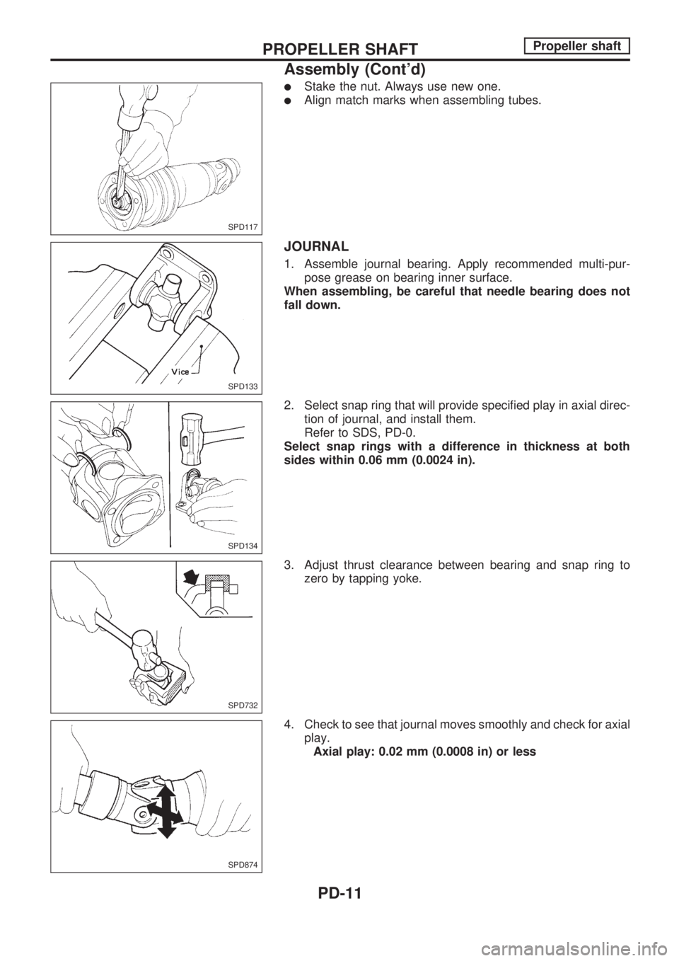
lStake the nut. Always use new one.
lAlign match marks when assembling tubes.
JOURNAL
1. Assemble journal bearing. Apply recommended multi-pur-
pose grease on bearing inner surface.
When assembling, be careful that needle bearing does not
fall down.
2. Select snap ring that will provide specified play in axial direc-
tion of journal, and install them.
Refer to SDS, PD-0.
Select snap rings with a difference in thickness at both
sides within 0.06 mm (0.0024 in).
3. Adjust thrust clearance between bearing and snap ring to
zero by tapping yoke.
4. Check to see that journal moves smoothly and check for axial
play.
Axial play: 0.02 mm (0.0008 in) or less
SPD117
SPD133
SPD134
SPD732
SPD874
PROPELLER SHAFTPropeller shaft
Assembly (Cont'd)
PD-11
Page 1093 of 1659
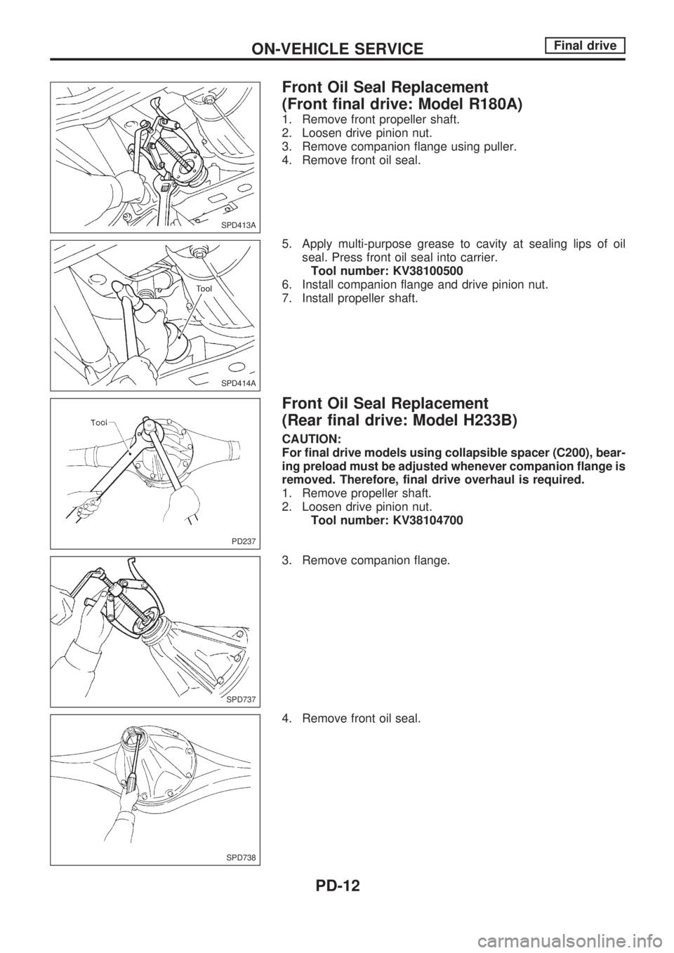
Front Oil Seal Replacement
(Front final drive: Model R180A)
1. Remove front propeller shaft.
2. Loosen drive pinion nut.
3. Remove companion flange using puller.
4. Remove front oil seal.
5. Apply multi-purpose grease to cavity at sealing lips of oil
seal. Press front oil seal into carrier.
Tool number: KV38100500
6. Install companion flange and drive pinion nut.
7. Install propeller shaft.
Front Oil Seal Replacement
(Rear final drive: Model H233B)
CAUTION:
For final drive models using collapsible spacer (C200), bear-
ing preload must be adjusted whenever companion flange is
removed. Therefore, final drive overhaul is required.
1. Remove propeller shaft.
2. Loosen drive pinion nut.
Tool number: KV38104700
3. Remove companion flange.
4. Remove front oil seal.
SPD413A
SPD414A
PD237
SPD737
SPD738
ON-VEHICLE SERVICEFinal drive
PD-12
Page 1094 of 1659
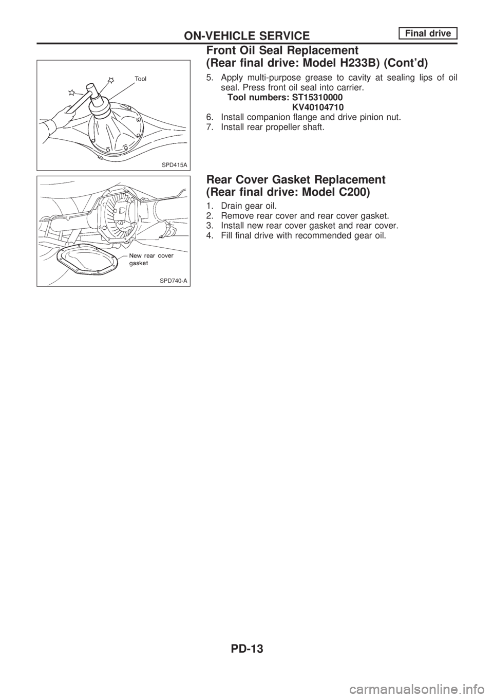
5. Apply multi-purpose grease to cavity at sealing lips of oil
seal. Press front oil seal into carrier.
Tool numbers: ST15310000
KV40104710
6. Install companion flange and drive pinion nut.
7. Install rear propeller shaft.
Rear Cover Gasket Replacement
(Rear final drive: Model C200)
1. Drain gear oil.
2. Remove rear cover and rear cover gasket.
3. Install new rear cover gasket and rear cover.
4. Fill final drive with recommended gear oil.
SPD415A
SPD740-A
ON-VEHICLE SERVICEFinal drive
Front Oil Seal Replacement
(Rear final drive: Model H233B) (Cont'd)
PD-13
Page 1095 of 1659
![NISSAN PICK-UP 1998 Repair Manual Removal
1. Remove front propeller shaft.
2. Remove drive shaft. Refer to FA section [``Drive Shaft,
``FRONT AXLE (4WD)].
3. Remove engine mounting bolts and raise up engine.
4. Remove front final NISSAN PICK-UP 1998 Repair Manual Removal
1. Remove front propeller shaft.
2. Remove drive shaft. Refer to FA section [``Drive Shaft,
``FRONT AXLE (4WD)].
3. Remove engine mounting bolts and raise up engine.
4. Remove front final](/img/5/57374/w960_57374-1094.png)
Removal
1. Remove front propeller shaft.
2. Remove drive shaft. Refer to FA section [``Drive Shaft'',
``FRONT AXLE (4WD)''].
3. Remove engine mounting bolts and raise up engine.
4. Remove front final drive together with differential mounting
member.
Installation
1. Install front final drive assembly together with differential
mounting member.
2. Tighten front final drive securing bolts and nuts by following
the procedure to prevent drive train vibration.
a. Temporarily tighten nut
VA.
b. Temporarily tighten nut
VB.
c. Tighten bolt
VCto the torque of 68 to 87 N´m (6.9 to 8.9 kg-m,
50 to 64 ft-lb).
d. Tighten bolt
VDto the torque of 68 to 87 N´m (6.9 to 8.9 kg-m,
50 to 64 ft-lb).
e. Tighten nut
VAto the torque of 68 to 87 N´m (6.9 to 8.9 kg-m,
50 to 64 ft-lb).
f. Tighten nut
VBto the torque of 68 to 87 N´m (6.9 to 8.9 kg-m,
50 to 64 ft-lb).
g. Tighten nut
VEto the torque of 68 to 87 N´m (6.9 to 8.9 kg-m,
50 to 64 ft-lb).
3. Install drive shaft. Refer to FA section [``Drive Shaft'',
``FRONT AXLE (4WD)''].
4. Install front propeller shaft.
SPD416A
SPD417A
SPD743
REMOVAL AND INSTALLATION (Front final drive)Final drive
PD-14
Page 1096 of 1659
Removal
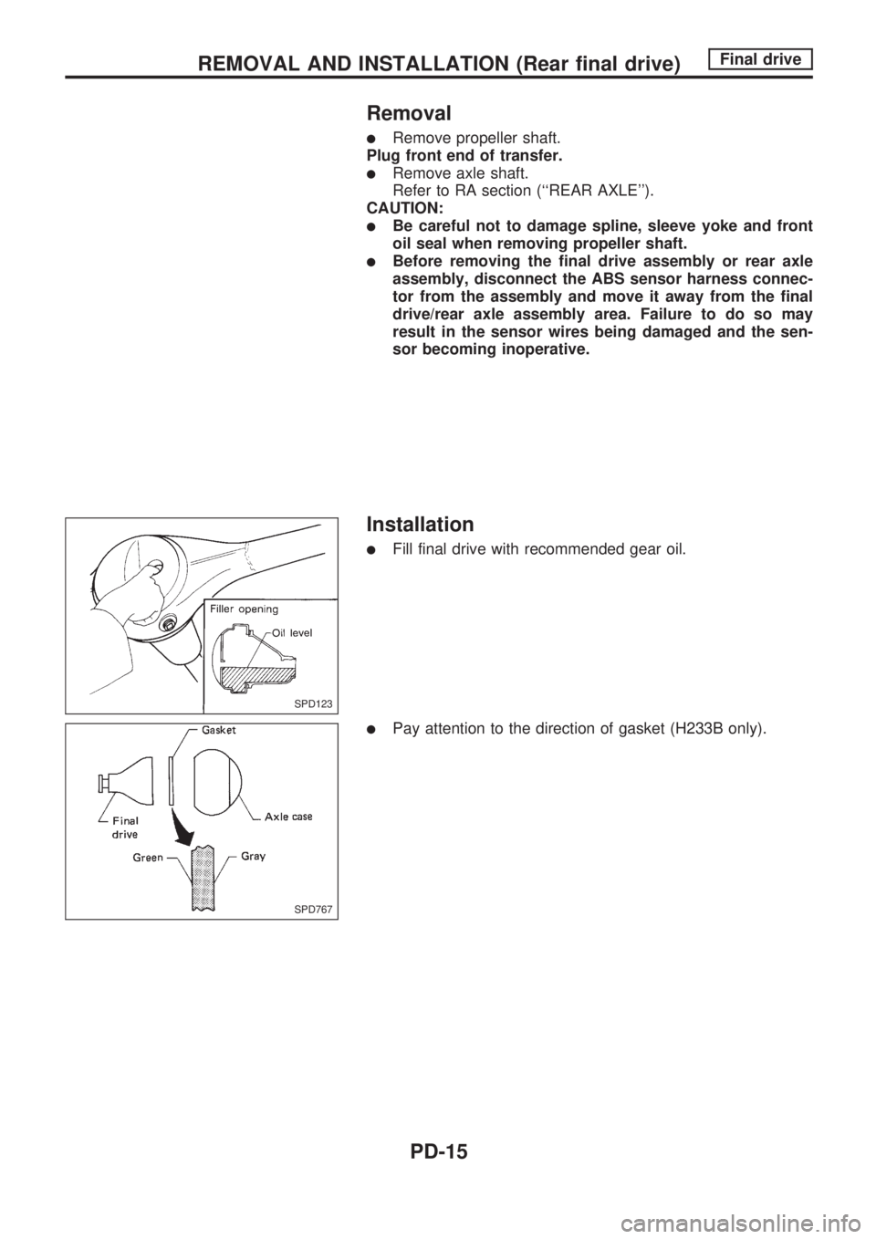
lRemove propeller shaft.
Plug front end of transfer.
lRemove axle shaft.
Refer to RA section (``REAR AXLE'').
CAUTION:
lBe careful not to damage spline, sleeve yoke and front
oil seal when removing propeller shaft.
lBefore removing the final drive assembly or rear axle
assembly, disconnect the ABS sensor harness connec-
tor from the assembly and move it away from the final
drive/rear axle assembly area. Failure to do so may
result in the sensor wires being damaged and the sen-
sor becoming inoperative.
Installation
lFill final drive with recommended gear oil.
lPay attention to the direction of gasket (H233B only).
SPD123
SPD767
REMOVAL AND INSTALLATION (Rear final drive)Final drive
PD-15
Page 1097 of 1659
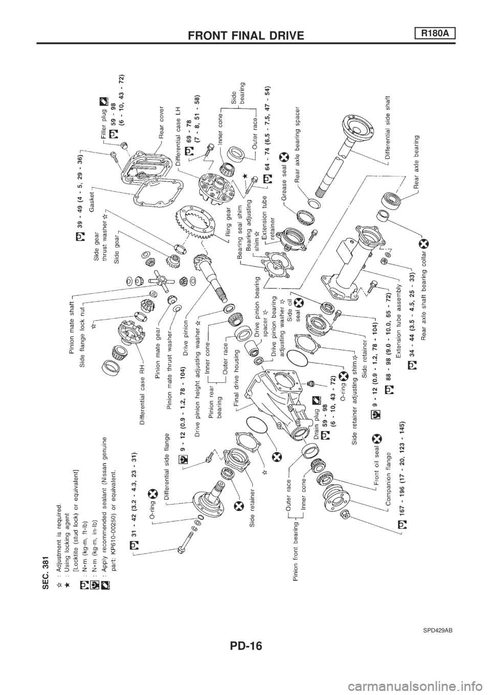
SPD429AB
FRONT FINAL DRIVER180A
PD-16
Page 1098 of 1659
Pre-inspection
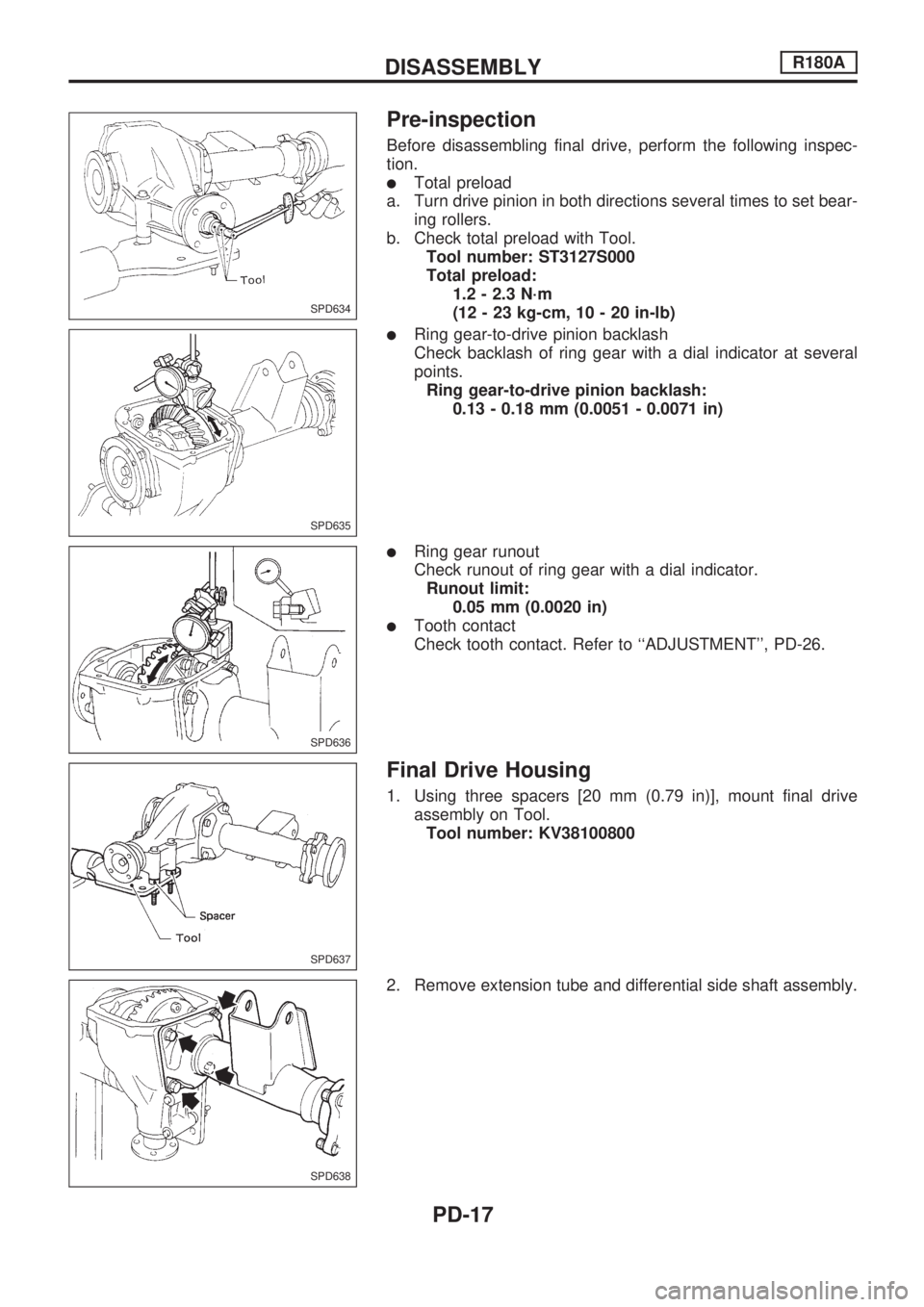
Before disassembling final drive, perform the following inspec-
tion.
lTotal preload
a. Turn drive pinion in both directions several times to set bear-
ing rollers.
b. Check total preload with Tool.
Tool number: ST3127S000
Total preload:
1.2 - 2.3 N´m
(12 - 23 kg-cm, 10 - 20 in-lb)
lRing gear-to-drive pinion backlash
Check backlash of ring gear with a dial indicator at several
points.
Ring gear-to-drive pinion backlash:
0.13 - 0.18 mm (0.0051 - 0.0071 in)
lRing gear runout
Check runout of ring gear with a dial indicator.
Runout limit:
0.05 mm (0.0020 in)
lTooth contact
Check tooth contact. Refer to ``ADJUSTMENT'', PD-26.
Final Drive Housing
1. Using three spacers [20 mm (0.79 in)], mount final drive
assembly on Tool.
Tool number: KV38100800
2. Remove extension tube and differential side shaft assembly.
SPD634
SPD635
SPD636
SPD637
SPD638
DISASSEMBLYR180A
PD-17
Page 1099 of 1659
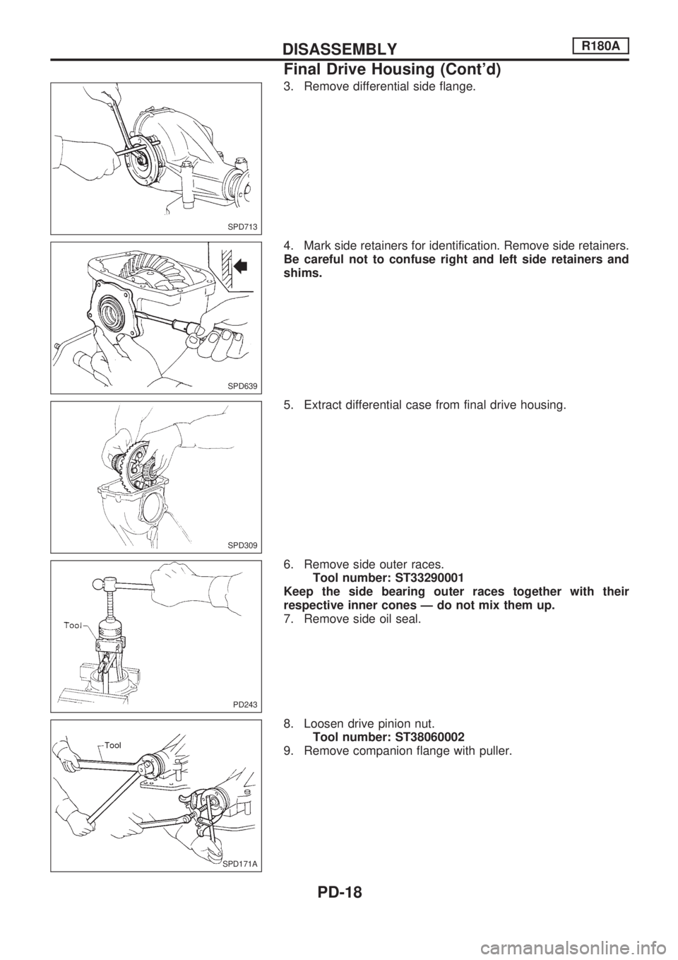
3. Remove differential side flange.
4. Mark side retainers for identification. Remove side retainers.
Be careful not to confuse right and left side retainers and
shims.
5. Extract differential case from final drive housing.
6. Remove side outer races.
Tool number: ST33290001
Keep the side bearing outer races together with their
respective inner cones Ð do not mix them up.
7. Remove side oil seal.
8. Loosen drive pinion nut.
Tool number: ST38060002
9. Remove companion flange with puller.
SPD713
SPD639
SPD309
PD243
SPD171A
DISASSEMBLYR180A
Final Drive Housing (Cont'd)
PD-18
Page 1100 of 1659
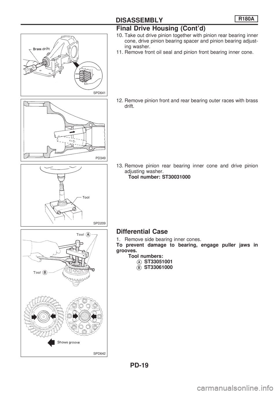
10. Take out drive pinion together with pinion rear bearing inner
cone, drive pinion bearing spacer and pinion bearing adjust-
ing washer.
11. Remove front oil seal and pinion front bearing inner cone.
12. Remove pinion front and rear bearing outer races with brass
drift.
13. Remove pinion rear bearing inner cone and drive pinion
adjusting washer.
Tool number: ST30031000
Differential Case
1. Remove side bearing inner cones.
To prevent damage to bearing, engage puller jaws in
grooves.
Tool numbers:
VAST33051001
VBST33061000
SPD641
PD349
SPD209
SPD642
DISASSEMBLYR180A
Final Drive Housing (Cont'd)
PD-19
Trending: EL 132, torque, fog light, relay, fuse box location, wheel torque, mileage
![NISSAN PICK-UP 1998 Repair Manual Removal
1. Remove front propeller shaft.
2. Remove drive shaft. Refer to FA section [``Drive Shaft,
``FRONT AXLE (4WD)].
3. Remove engine mounting bolts and raise up engine.
4. Remove front final NISSAN PICK-UP 1998 Repair Manual Removal
1. Remove front propeller shaft.
2. Remove drive shaft. Refer to FA section [``Drive Shaft,
``FRONT AXLE (4WD)].
3. Remove engine mounting bolts and raise up engine.
4. Remove front final](/img/5/57374/w960_57374-1094.png)
