NISSAN PICK-UP 1998 Repair Manual
Manufacturer: NISSAN, Model Year: 1998, Model line: PICK-UP, Model: NISSAN PICK-UP 1998Pages: 1659, PDF Size: 53.39 MB
Page 1441 of 1659
CATS (Code) System/For Europe RHD
NOTE:
lThis system is used for code indicator-equipped radios on all models.
lThe Europe LHD model with KA24E engine has a NATS-linked anti-theft function with radio as
optional equipment that renders the code system inoperable.
DESCRIPTION
By using a personal 4-digit code known only to the vehicle owner, the possibility of the audio unit being sto-
len is effectively reduced, because without the code the unit can not be activated. When in normal use, the
unit is unlocked and accessible in the usual way.
If however, someone attempts to remove the unit or the battery cable is disconnected, the anti-theft system
activates and the unit ``locks''. The only way it can be unlocked is by entering a personal code number known
only by the owner.
UNLOCKING THE UNIT (How to enter a personal code number)
lIf the battery supply to the vehicle is interrupted by accident for some reason, the unit will lock.
To unlock the unit, proceed as follows:
1. Press the power/volume control knob to turn the unit on.
2. ``CODE IN'' is displayed.
3. Input your personal code by pressing the preset buttons (1 to 4).
4. Press the
button.
5. If the entered code number is correct, the radio turns on.
When the code is incorrect
1. If the entered code is incorrect, the unit becomes inoperable for 10 seconds for the first three attempts,
then the code input mode is automatically set (``CODE IN'' is displayed).
2. If the code is incorrect the fourth time, the unit becomes inoperable for 60 minutes and ``
'' is dis-
played. After 60 minutes, the code input mode is automatically set (``CODE IN'' is displayed).
NOTE:
If the above is repeated 17 times, the unit will lock and ``LOCKED'' is displayed.
3. After ``LOCKED'' is displayed, radio can be returned to the code input mode only within three attempts
as follows. (Only three attempts are allowed to unlock the unit.)
a. Press the power/volume control knob while pushing both the MOD and TA switches.
b. The unit then returns to the code input mode.
CAUTION:
If the third attempt is unsuccessful, the unit will lock permanently.
AUDIO
EL-143
Page 1442 of 1659
NATS Audio Link/For Europe LHD (KA24E)
DESCRIPTION
The Europe LHD model with KA24E engine has a NATS-linked anti-theft function with radio as optional
equipment.
The link with the NATS IMMU implies that the radio can basically only be operated if connected to the
matching NATS IMMU to which the radio was initially fitted on the production line.
Since radio operation is impossible after the link with the NATS is disrupted theft of the radio unit is basi-
cally useless since special equipment is required to reset the radio.
Initialisation process for radios that are linked to the NATS IMMU
New radios will be delivered to the factories in the ``NEW'' state, i.e. ready to be linked with the vehicle's
NATS.
When the radio in ``NEW'' state is first switched on at the factory, it will start up communication with the
vehicle's immobiliser control unit (IMMU) and send a code (the ``Radio Code'') to the IMMU. The IMMU will
then store this code, which is unique to each radio, in its (permanent) memory.
Upon receipt of the code by the IMMU, the NATS will confirm correct receipt of the radio code to the radio.
Hereafter, the radio will operate as normal.
During the initialisation process, ``NEW'' is displayed on the radio display. Normally though, communication
between Radio and IMMU takes such a short time (300 ms) that the radio seems to switch on directly with-
out showing ``NEW'' on its display.
Normal operation
Each time the radio is switched on afterwards, the radio code will be verified between the radio unit and the
NATS before the radio becomes operational. During the code verification process, ``WAIT'' is shown on the
radio display. Again, the communication takes such a short time (300 ms) that the radio seems to switch on
directly without showing ``WAIT'' on its display.
When the radio is locked
In case of a radio being linked with the vehicle's NATS (immobiliser system), disconnection of the link
between the radio and the IMMU will cause the radio to switch into the lock (``SECURE'') mode in which the
radio unit is fully inoperative. Hence, repair of the radio is basically impossible, unless the radio is reset to
the ``NEW'' state for which special decoding equipment is required.
Both Blaupunkt and Clarion have provided their authorized service representatives with so called ``decoder
boxes'' which can bring the radio unit back to the ``NEW'' state, enabling the radio to be switched on after
which repair can be carried out. Subsequently, when the repaired radio is delivered to the final user again,
it will be in the ``NEW'' state as to enable re-linking the radio to the vehicle's immobiliser system. As a result
of the above, repair of the radio can only be done by an authorized Blaupunkt or Clarion representative.
Note:
Radio manufacturer of Nissan D22 models for Europe is ``Clarion''.
SERVICE PROCEDURE
Item Service procedure Description
Battery disconnection No additional action required. Ð
Radio needs repair Repair needs to be done by authorized represen-
tative of radio manufacturer since radio cannot
be operated unless it is reset to NEW state,
using special decoding equipment.Ð
Replacement of radio by new
partNo additional action required. Radio is delivered in NEW state.
Transferring radio to another
vehicle/replacement of radio
by an ``old'' partRadio needs to be reset to NEW state by autho-
rized representative of radio manufacturer.Ð
AUDIO
EL-144
Page 1443 of 1659
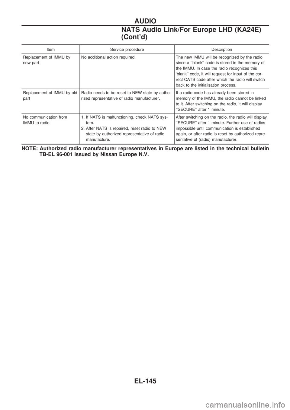
Item Service procedure Description
Replacement of IMMU by
new partNo additional action required. The new IMMU will be recognized by the radio
since a ``blank'' code is stored in the memory of
the IMMU. In case the radio recognizes this
`blank'' code, it will request for input of the cor-
rect CATS code after which the radio will switch
back to the initialisation process.
Replacement of IMMU by old
partRadio needs to be reset to NEW state by autho-
rized representative of radio manufacturer.If a radio code has already been stored in
memory of the IMMU, the radio cannot be linked
to it. After switching on the radio, it will display
``SECURE'' after 1 minute.
No communication from
IMMU to radio1. If NATS is malfunctioning, check NATS sys-
tem.
2. After NATS is repaired, reset radio to NEW
state by authorized representative of radio
manufacture.After switching on the radio, the radio will display
``SECURE'' after 1 minute. Further use of radios
impossible until communication is established
again, or after radio is reset by authorized repre-
sentative of (radio) manufacturer.
NOTE: Authorized radio manufacturer representatives in Europe are listed in the technical bulletin
TB-EL 96-001 issued by Nissan Europe N.V.
AUDIO
NATS Audio Link/For Europe LHD (KA24E)
(Cont'd)
EL-145
Page 1444 of 1659
Manual Antenna
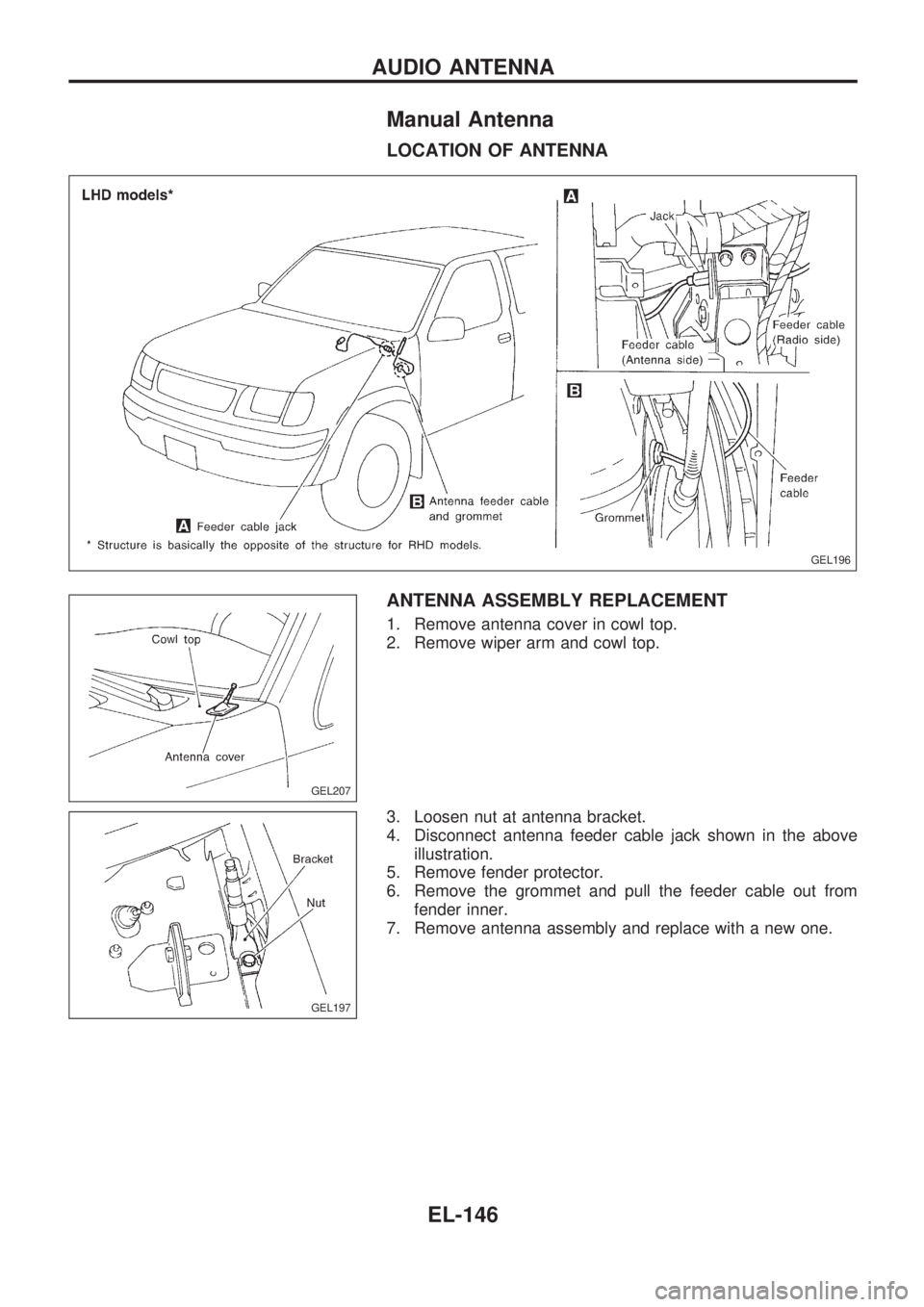
LOCATION OF ANTENNA
ANTENNA ASSEMBLY REPLACEMENT
1. Remove antenna cover in cowl top.
2. Remove wiper arm and cowl top.
3. Loosen nut at antenna bracket.
4. Disconnect antenna feeder cable jack shown in the above
illustration.
5. Remove fender protector.
6. Remove the grommet and pull the feeder cable out from
fender inner.
7. Remove antenna assembly and replace with a new one.
GEL196
GEL207
GEL197
AUDIO ANTENNA
EL-146
Page 1445 of 1659
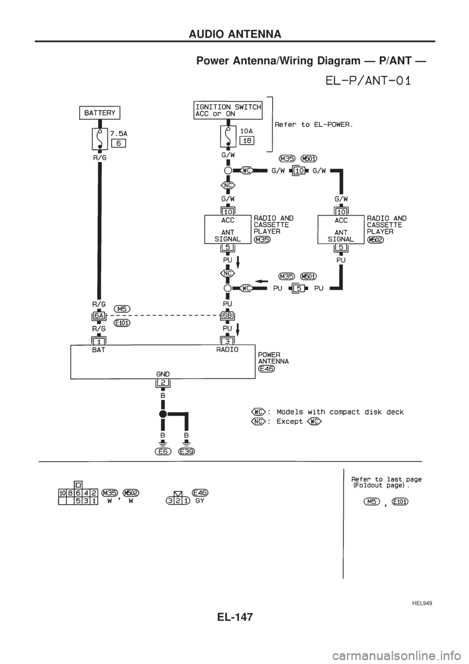
Power Antenna/Wiring Diagram Ð P/ANT Ð
HEL949
AUDIO ANTENNA
EL-147
Page 1446 of 1659
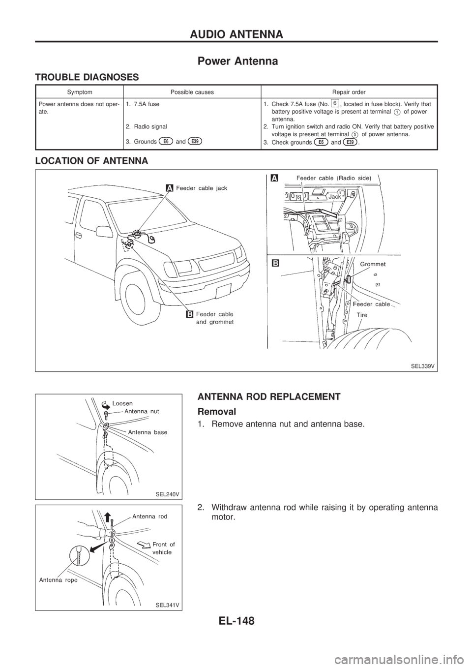
Power Antenna
TROUBLE DIAGNOSES
Symptom Possible causes Repair order
Power antenna does not oper-
ate.1. 7.5A fuse
2. Radio signal
3. Grounds
E6andE39
1. Check 7.5A fuse (No.6, located in fuse block). Verify that
battery positive voltage is present at terminal
V1of power
antenna.
2. Turn ignition switch and radio ON. Verify that battery positive
voltage is present at terminal
V3of power antenna.
3. Check groundsE6andE39.
LOCATION OF ANTENNA
ANTENNA ROD REPLACEMENT
Removal
1. Remove antenna nut and antenna base.
2. Withdraw antenna rod while raising it by operating antenna
motor.
SEL339V
SEL240V
SEL341V
AUDIO ANTENNA
EL-148
Page 1447 of 1659
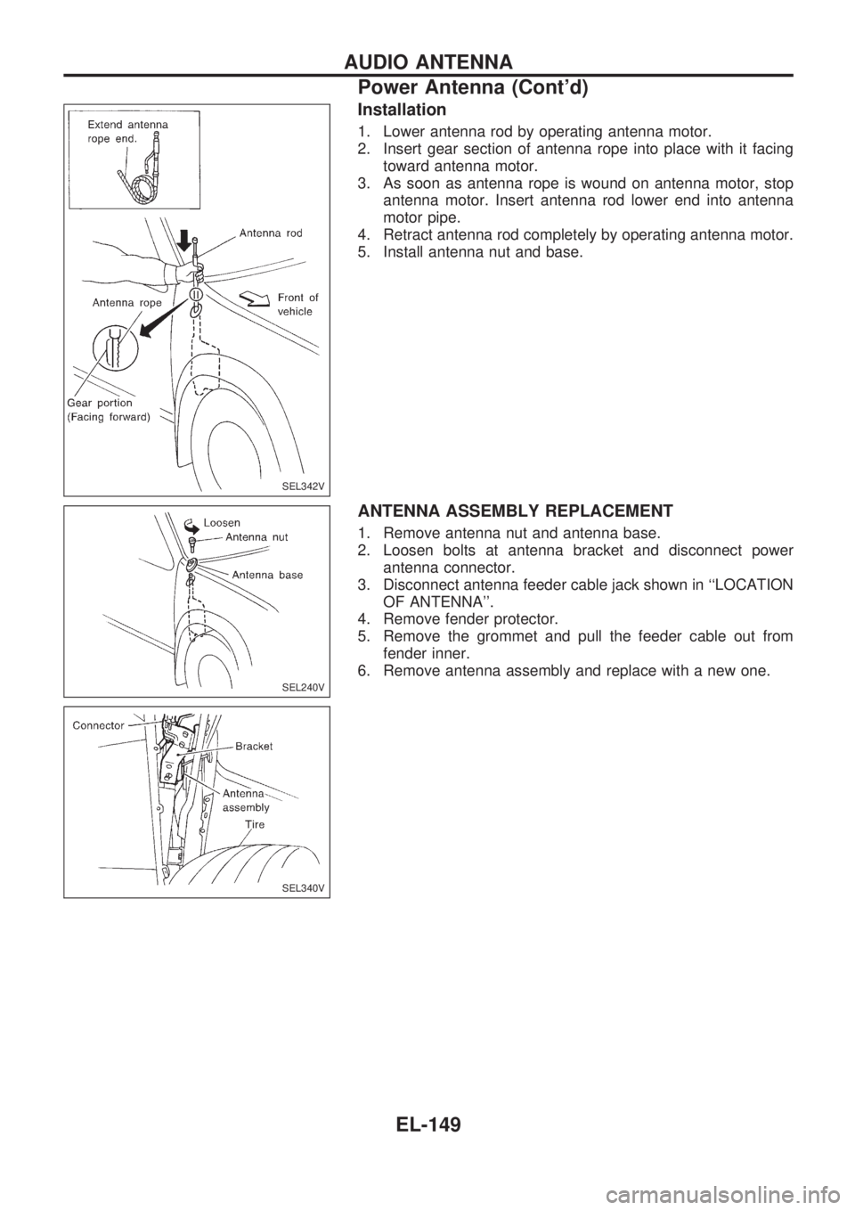
Installation
1. Lower antenna rod by operating antenna motor.
2. Insert gear section of antenna rope into place with it facing
toward antenna motor.
3. As soon as antenna rope is wound on antenna motor, stop
antenna motor. Insert antenna rod lower end into antenna
motor pipe.
4. Retract antenna rod completely by operating antenna motor.
5. Install antenna nut and base.
ANTENNA ASSEMBLY REPLACEMENT
1. Remove antenna nut and antenna base.
2. Loosen bolts at antenna bracket and disconnect power
antenna connector.
3. Disconnect antenna feeder cable jack shown in ``LOCATION
OF ANTENNA''.
4. Remove fender protector.
5. Remove the grommet and pull the feeder cable out from
fender inner.
6. Remove antenna assembly and replace with a new one.
SEL342V
SEL240V
SEL340V
AUDIO ANTENNA
Power Antenna (Cont'd)
EL-149
Page 1448 of 1659
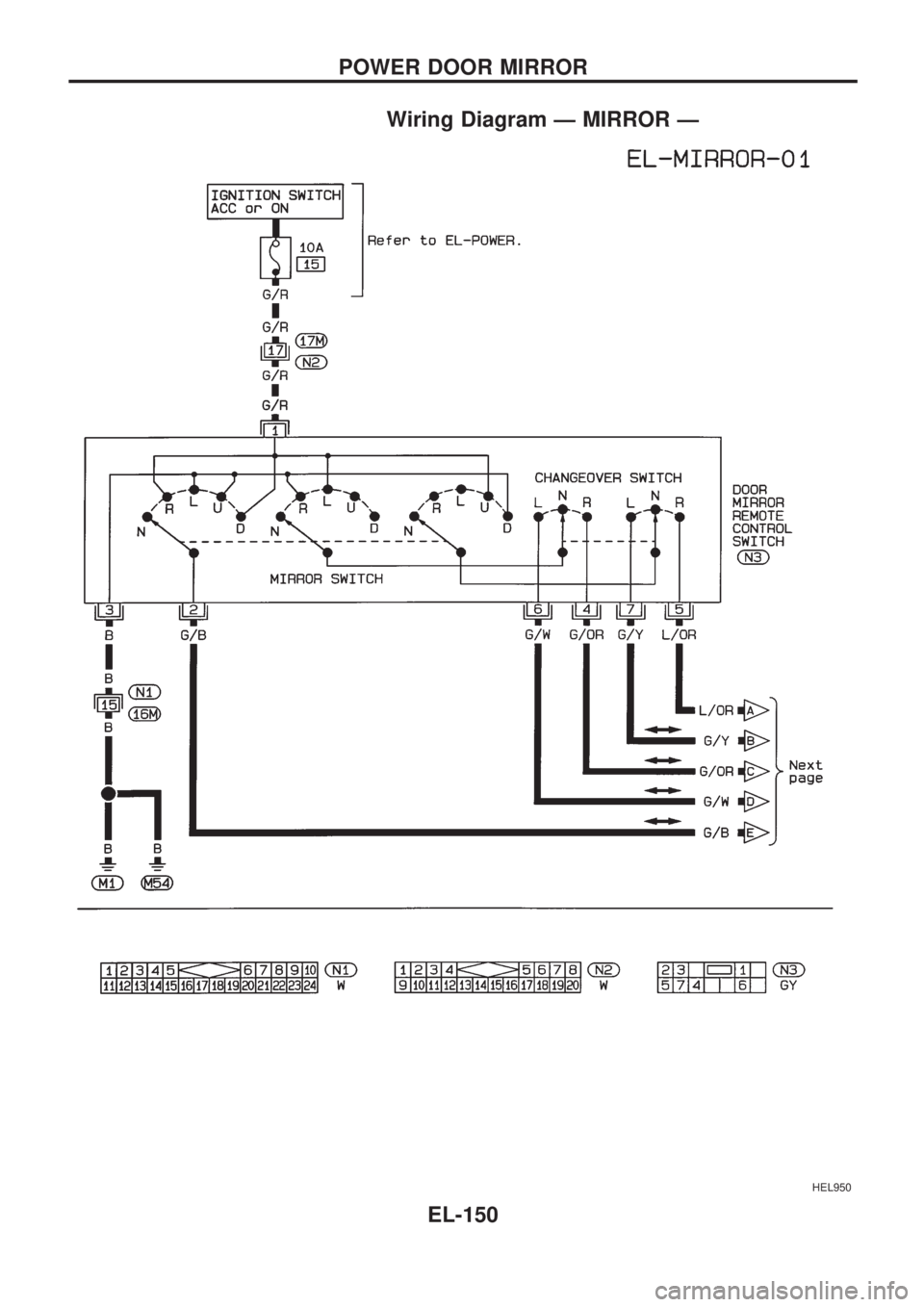
Wiring Diagram Ð MIRROR Ð
HEL950
POWER DOOR MIRROR
EL-150
Page 1449 of 1659
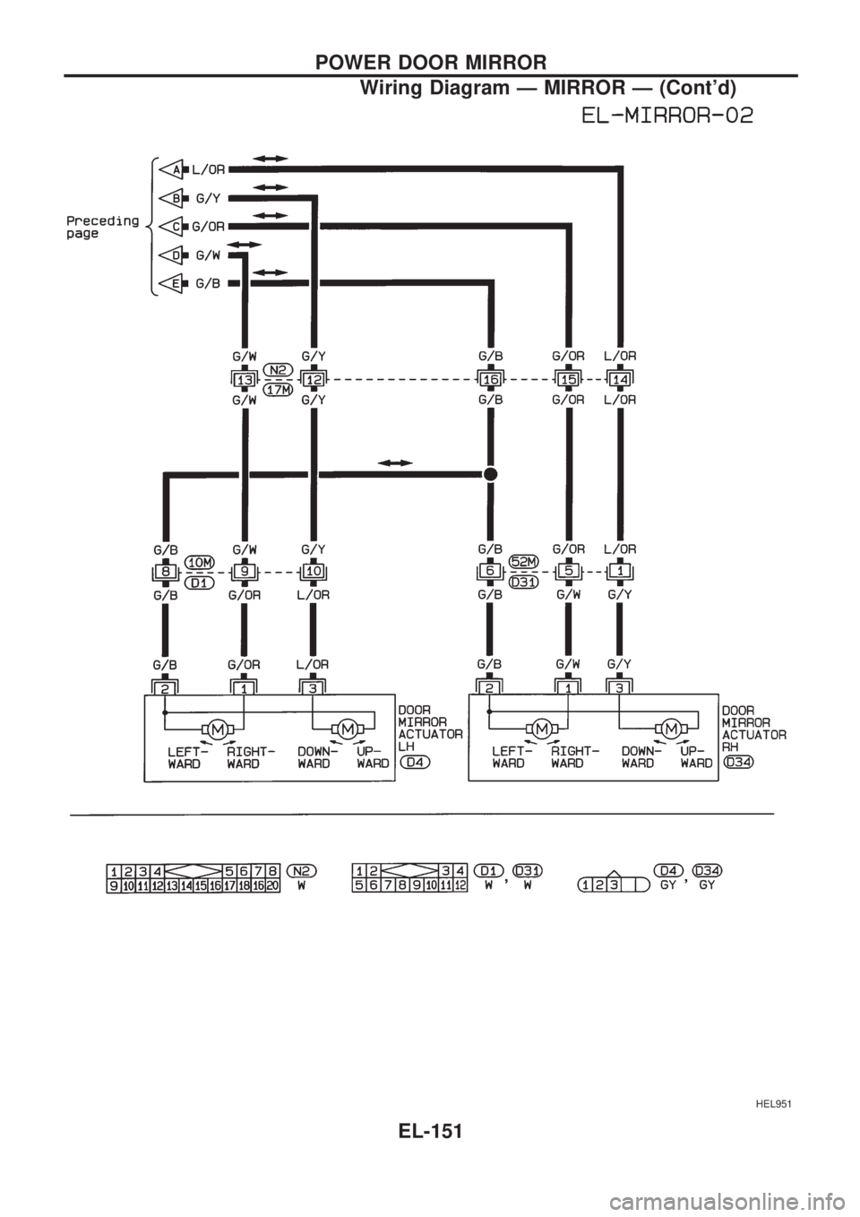
HEL951
POWER DOOR MIRROR
Wiring Diagram Ð MIRROR Ð (Cont'd)
EL-151
Page 1450 of 1659
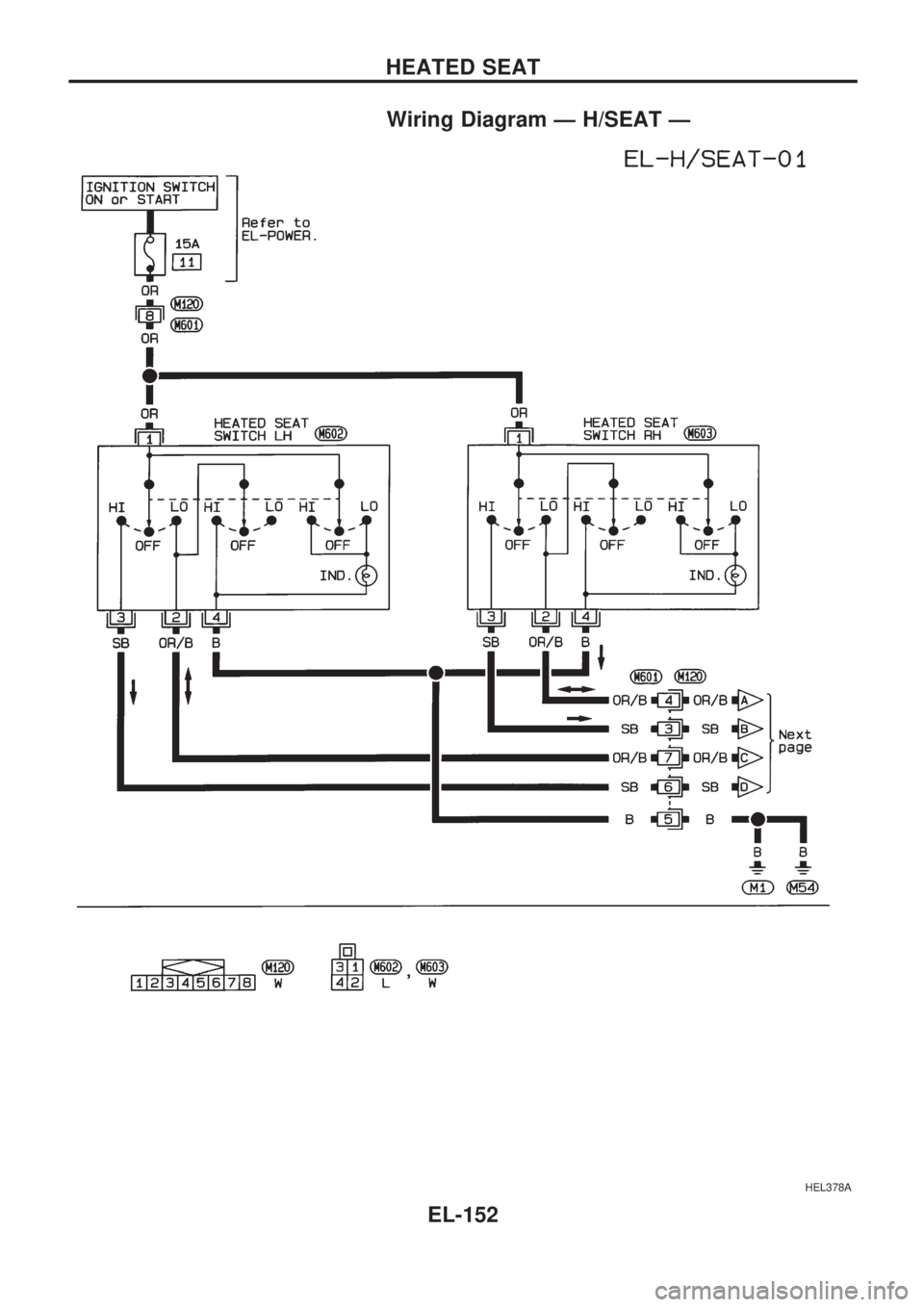
Wiring Diagram Ð H/SEAT Ð
HEL378A
HEATED SEAT
EL-152