NISSAN PICK-UP 1998 Repair Manual
PICK-UP 1998
NISSAN
NISSAN
https://www.carmanualsonline.info/img/5/57374/w960_57374-0.png
NISSAN PICK-UP 1998 Repair Manual
Trending: coolant level, battery, fuse diagram, automatic transmission fluid, wheel bolts, check engine, lug pattern
Page 1411 of 1659
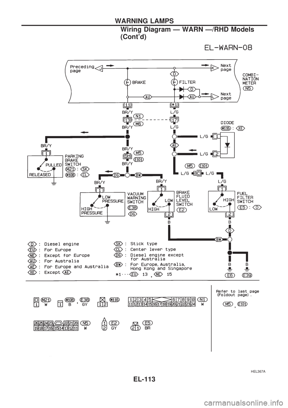
HEL367A
WARNING LAMPS
Wiring Diagram Ð WARN Ð/RHD Models
(Cont'd)
EL-113
Page 1412 of 1659
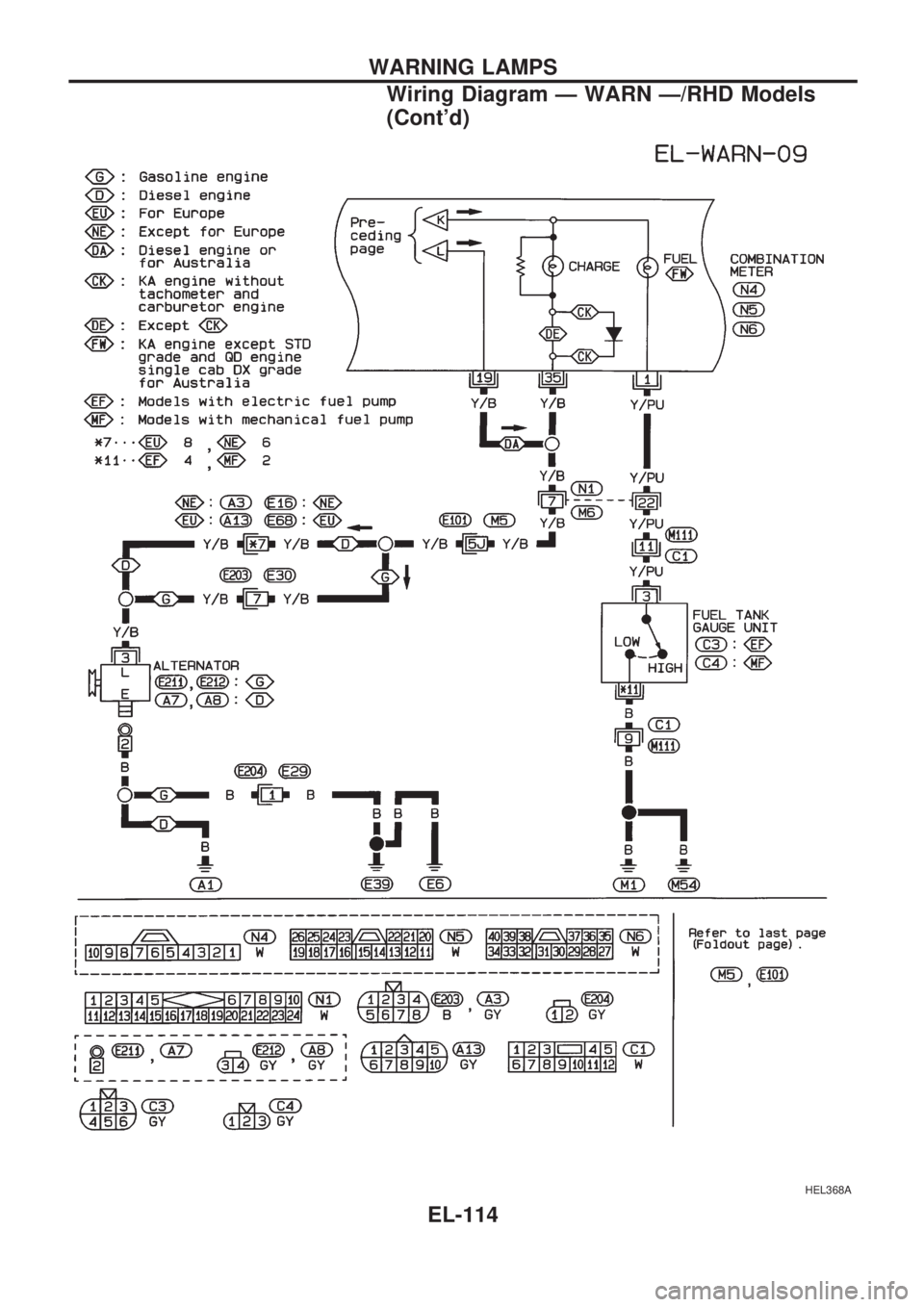
HEL368A
WARNING LAMPS
Wiring Diagram Ð WARN Ð/RHD Models
(Cont'd)
EL-114
Page 1413 of 1659
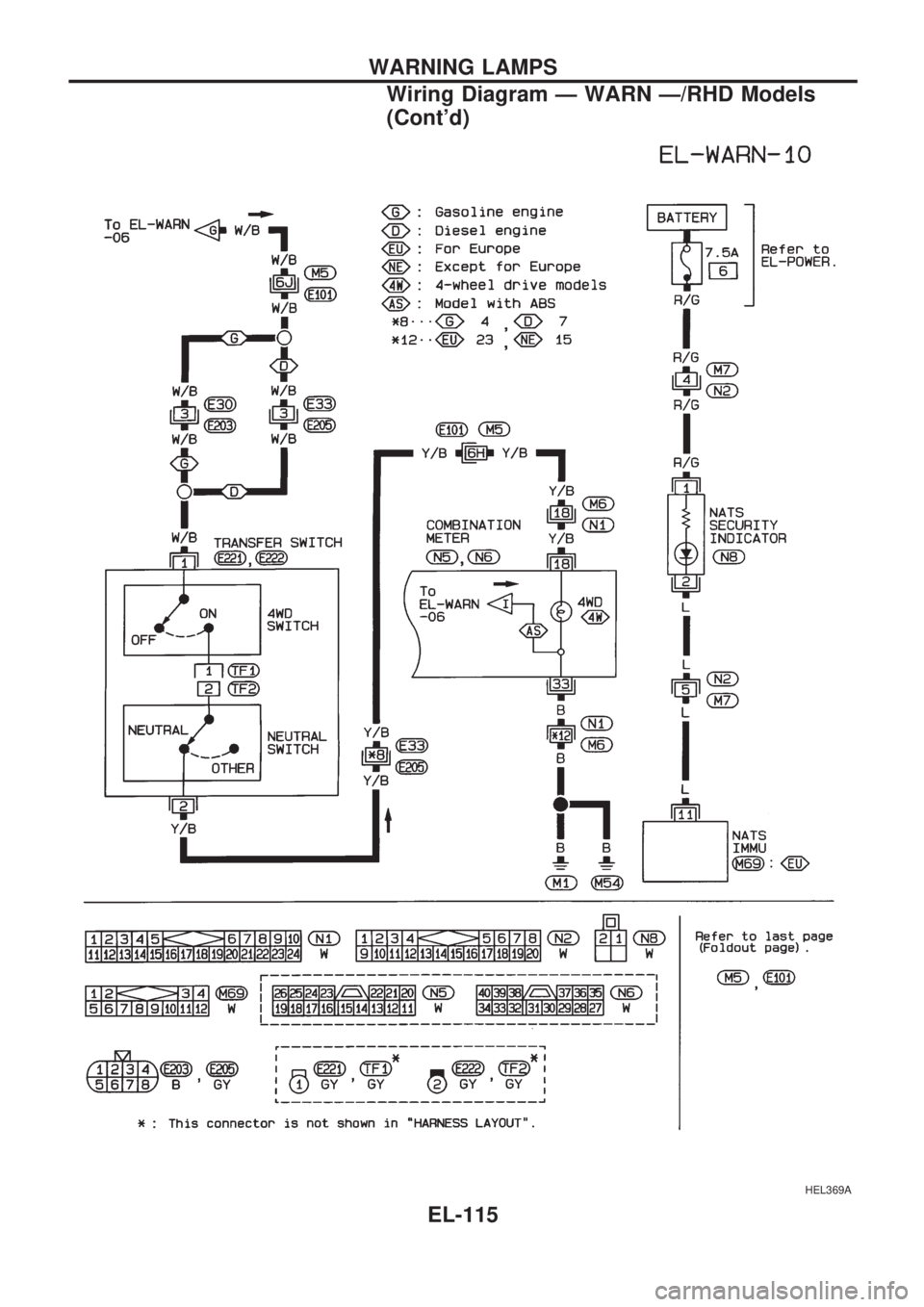
HEL369A
WARNING LAMPS
Wiring Diagram Ð WARN Ð/RHD Models
(Cont'd)
EL-115
Page 1414 of 1659
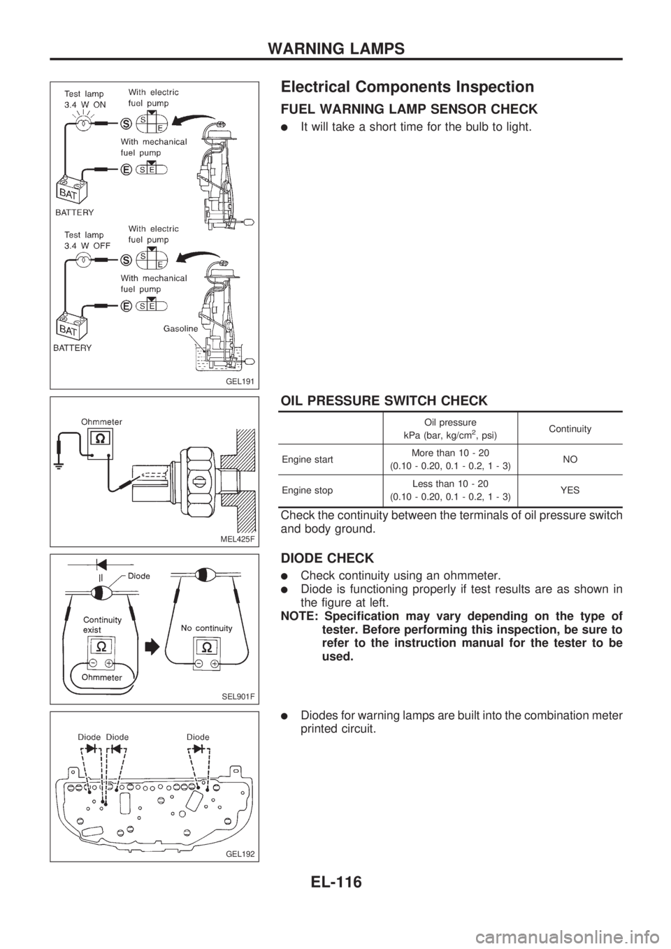
Electrical Components Inspection
FUEL WARNING LAMP SENSOR CHECK
lIt will take a short time for the bulb to light.
OIL PRESSURE SWITCH CHECK
Oil pressure
kPa (bar, kg/cm2, psi)Continuity
Engine startMore than 10 - 20
(0.10 - 0.20, 0.1 - 0.2,1-3)NO
Engine stopLess than 10 - 20
(0.10 - 0.20, 0.1 - 0.2,1-3)YES
Check the continuity between the terminals of oil pressure switch
and body ground.
DIODE CHECK
lCheck continuity using an ohmmeter.
lDiode is functioning properly if test results are as shown in
the figure at left.
NOTE: Specification may vary depending on the type of
tester. Before performing this inspection, be sure to
refer to the instruction manual for the tester to be
used.
lDiodes for warning lamps are built into the combination meter
printed circuit.
GEL191
MEL425F
SEL901F
GEL192
WARNING LAMPS
EL-116
Page 1415 of 1659
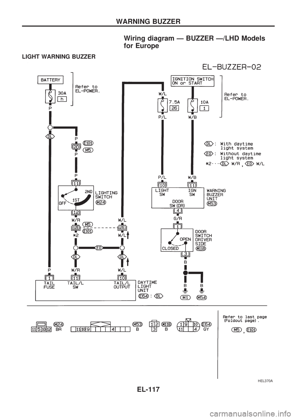
Wiring diagram Ð BUZZER Ð/LHD Models
for Europe
LIGHT WARNING BUZZER
HEL370A
WARNING BUZZER
EL-117
Page 1416 of 1659
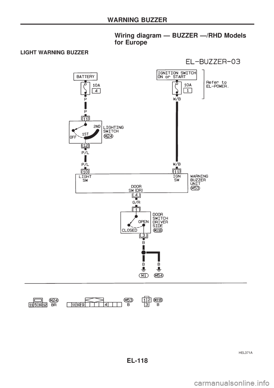
Wiring diagram Ð BUZZER Ð/RHD Models
for Europe
LIGHT WARNING BUZZER
HEL371A
WARNING BUZZER
EL-118
Page 1417 of 1659
Electrical Components Inspection
FUEL FILTER WARNING BUZZER CHECK
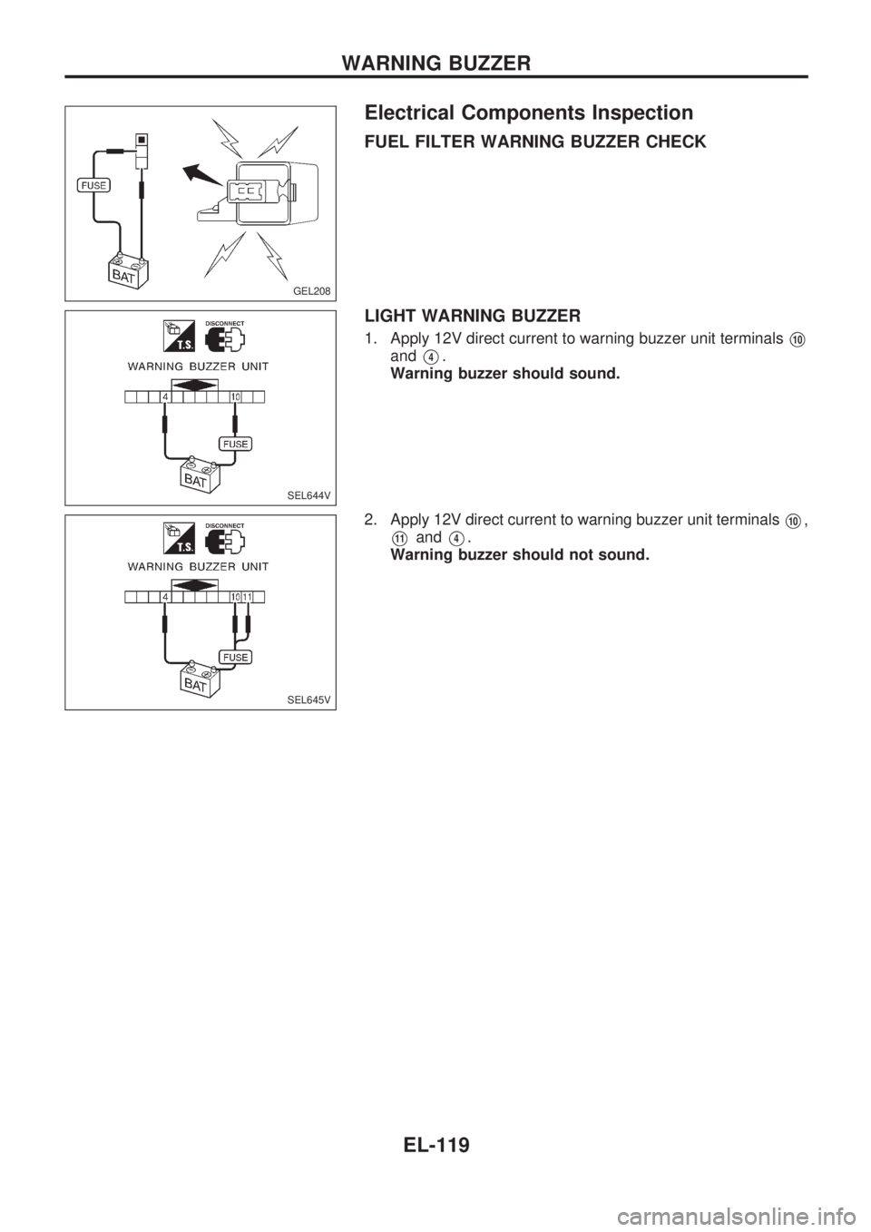
LIGHT WARNING BUZZER
1. Apply 12V direct current to warning buzzer unit terminalsV10
andV4.
Warning buzzer should sound.
2. Apply 12V direct current to warning buzzer unit terminals
V10,
V11andV4.
Warning buzzer should not sound.
GEL208
SEL644V
SEL645V
WARNING BUZZER
EL-119
Page 1418 of 1659
System Description
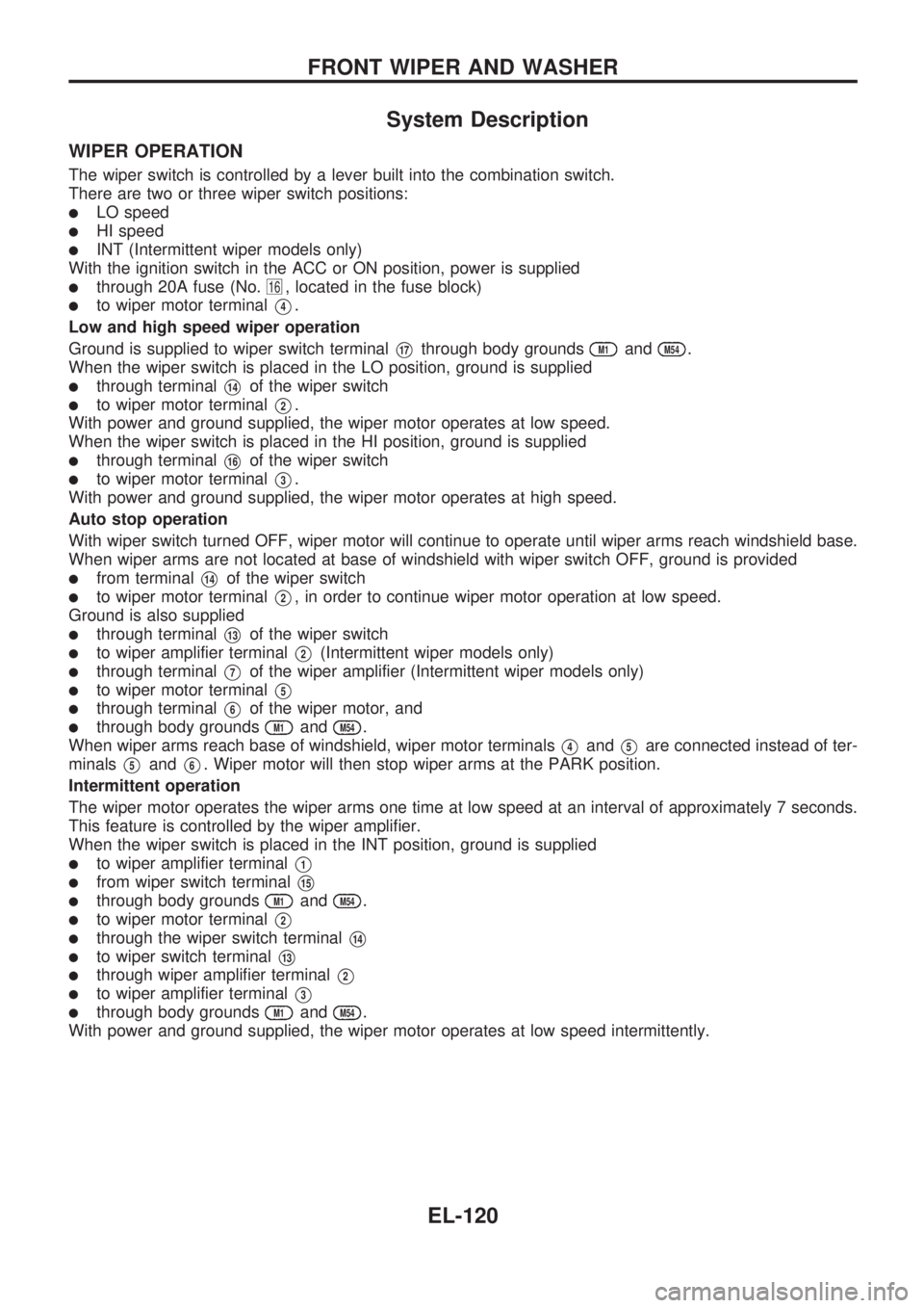
WIPER OPERATION
The wiper switch is controlled by a lever built into the combination switch.
There are two or three wiper switch positions:
lLO speed
lHI speed
lINT (Intermittent wiper models only)
With the ignition switch in the ACC or ON position, power is supplied
lthrough 20A fuse (No.16, located in the fuse block)
lto wiper motor terminalV4.
Low and high speed wiper operation
Ground is supplied to wiper switch terminal
V17through body groundsM1andM54.
When the wiper switch is placed in the LO position, ground is supplied
lthrough terminalV14of the wiper switch
lto wiper motor terminalV2.
With power and ground supplied, the wiper motor operates at low speed.
When the wiper switch is placed in the HI position, ground is supplied
lthrough terminalV16of the wiper switch
lto wiper motor terminalV3.
With power and ground supplied, the wiper motor operates at high speed.
Auto stop operation
With wiper switch turned OFF, wiper motor will continue to operate until wiper arms reach windshield base.
When wiper arms are not located at base of windshield with wiper switch OFF, ground is provided
lfrom terminalV14of the wiper switch
lto wiper motor terminalV2, in order to continue wiper motor operation at low speed.
Ground is also supplied
lthrough terminalV13of the wiper switch
lto wiper amplifier terminalV2(Intermittent wiper models only)
lthrough terminalV7of the wiper amplifier (Intermittent wiper models only)
lto wiper motor terminalV5
lthrough terminalV6of the wiper motor, and
lthrough body groundsM1andM54.
When wiper arms reach base of windshield, wiper motor terminals
V4andV5are connected instead of ter-
minals
V5andV6. Wiper motor will then stop wiper arms at the PARK position.
Intermittent operation
The wiper motor operates the wiper arms one time at low speed at an interval of approximately 7 seconds.
This feature is controlled by the wiper amplifier.
When the wiper switch is placed in the INT position, ground is supplied
lto wiper amplifier terminalV1
lfrom wiper switch terminalV15
lthrough body groundsM1andM54.
lto wiper motor terminalV2
lthrough the wiper switch terminalV14
lto wiper switch terminalV13
lthrough wiper amplifier terminalV2
lto wiper amplifier terminalV3
lthrough body groundsM1andM54.
With power and ground supplied, the wiper motor operates at low speed intermittently.
FRONT WIPER AND WASHER
EL-120
Page 1419 of 1659
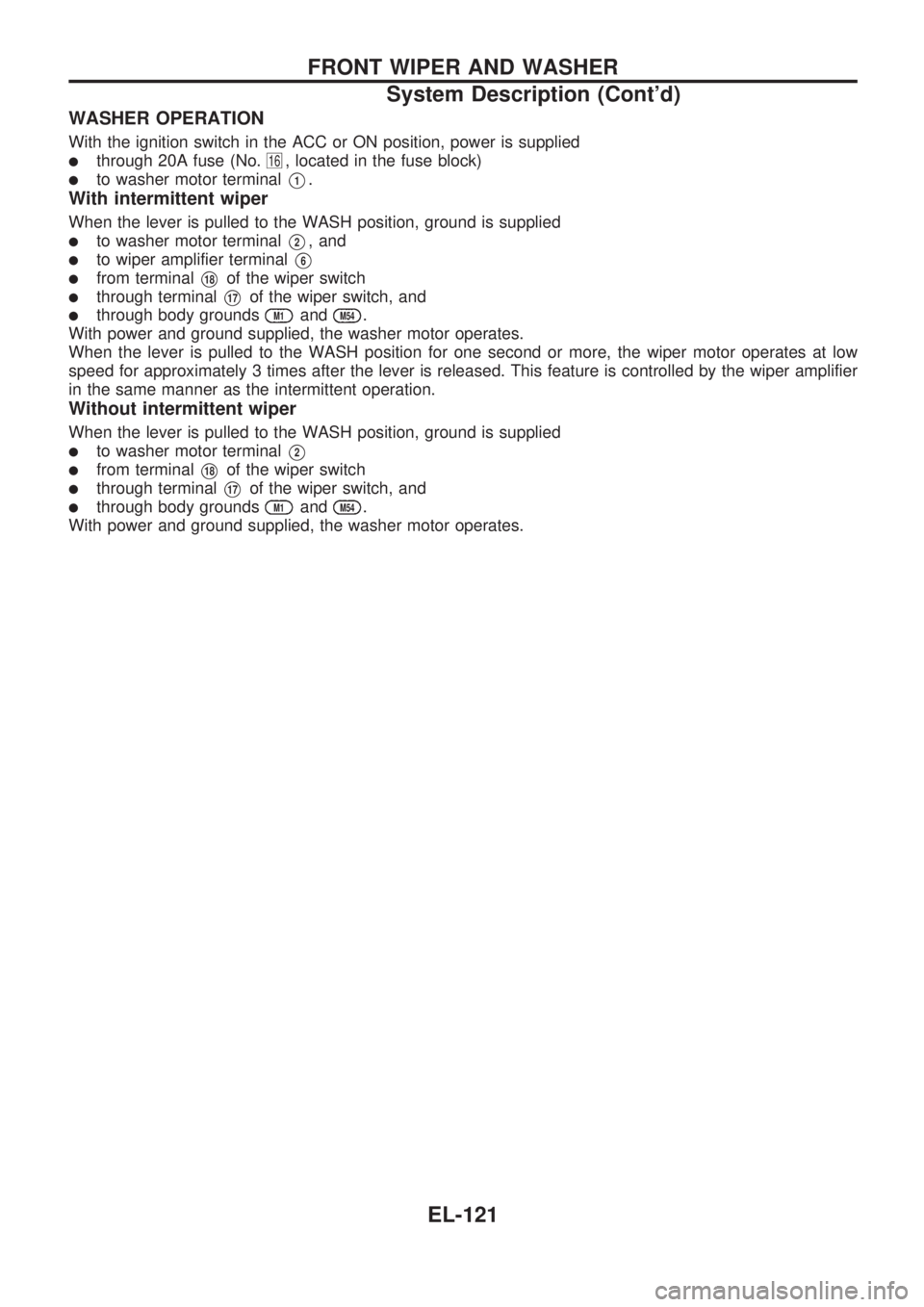
WASHER OPERATION
With the ignition switch in the ACC or ON position, power is supplied
lthrough 20A fuse (No.16, located in the fuse block)
lto washer motor terminalV1.
With intermittent wiper
When the lever is pulled to the WASH position, ground is supplied
lto washer motor terminalV2, and
lto wiper amplifier terminalV6
lfrom terminalV18of the wiper switch
lthrough terminalV17of the wiper switch, and
lthrough body groundsM1andM54.
With power and ground supplied, the washer motor operates.
When the lever is pulled to the WASH position for one second or more, the wiper motor operates at low
speed for approximately 3 times after the lever is released. This feature is controlled by the wiper amplifier
in the same manner as the intermittent operation.
Without intermittent wiper
When the lever is pulled to the WASH position, ground is supplied
lto washer motor terminalV2
lfrom terminalV18of the wiper switch
lthrough terminalV17of the wiper switch, and
lthrough body groundsM1andM54.
With power and ground supplied, the washer motor operates.
FRONT WIPER AND WASHER
System Description (Cont'd)
EL-121
Page 1420 of 1659
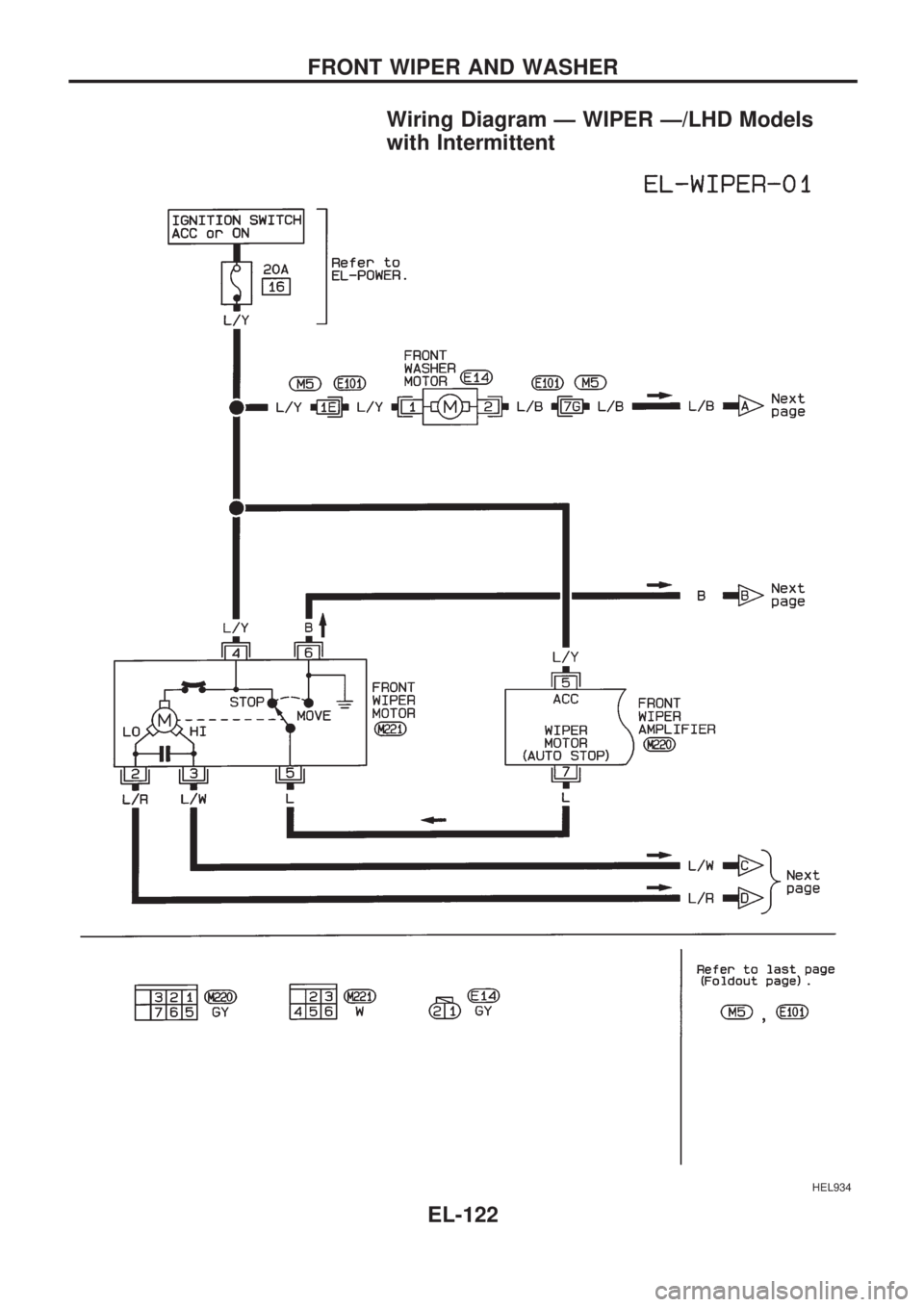
Wiring Diagram Ð WIPER Ð/LHD Models
with Intermittent
HEL934
FRONT WIPER AND WASHER
EL-122
Trending: change time, keyless, fuel cap release, steering wheel adjustment, fuel cap, inflation pressure, ad blue
