NISSAN PICK-UP 1998 Repair Manual
PICK-UP 1998
NISSAN
NISSAN
https://www.carmanualsonline.info/img/5/57374/w960_57374-0.png
NISSAN PICK-UP 1998 Repair Manual
Trending: Light, wheel alignment, checking oil, gas tank size, jump cable, remote control, lug pattern
Page 1461 of 1659
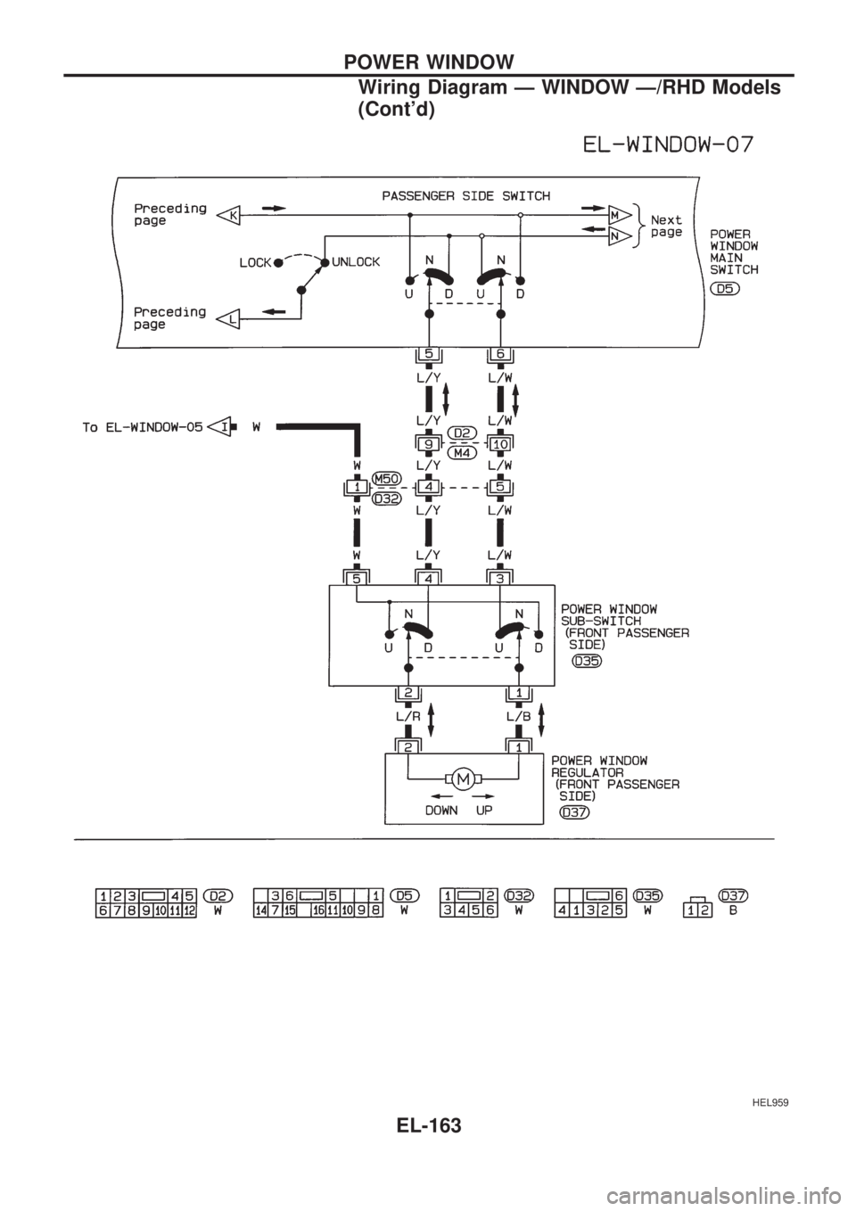
HEL959
POWER WINDOW
Wiring Diagram Ð WINDOW Ð/RHD Models
(Cont'd)
EL-163
Page 1462 of 1659
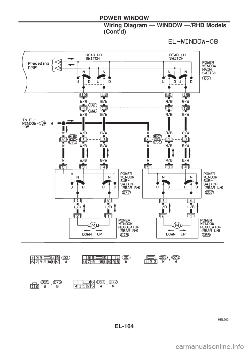
HEL960
POWER WINDOW
Wiring Diagram Ð WINDOW Ð/RHD Models
(Cont'd)
EL-164
Page 1463 of 1659
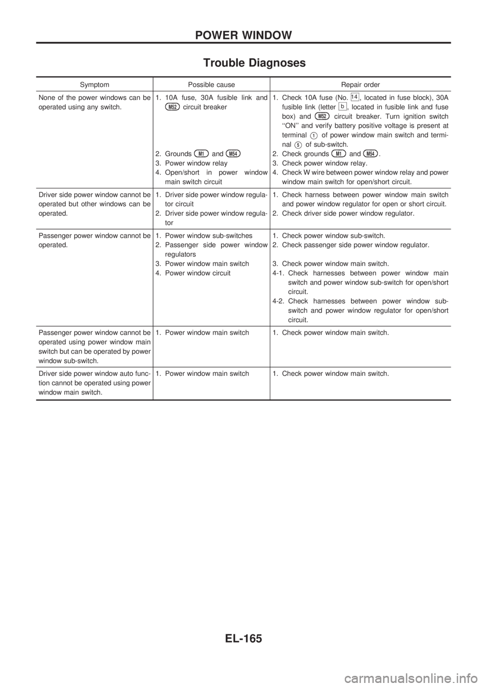
Trouble Diagnoses
Symptom Possible cause Repair order
None of the power windows can be
operated using any switch.1. 10A fuse, 30A fusible link and
M52circuit breaker
2. Grounds
M1andM54
3. Power window relay
4. Open/short in power window
main switch circuit1. Check 10A fuse (No.
14, located in fuse block), 30A
fusible link (letter
b, located in fusible link and fuse
box) and
M52circuit breaker. Turn ignition switch
``ON'' and verify battery positive voltage is present at
terminal
V1of power window main switch and termi-
nal
V5of sub-switch.
2. Check grounds
M1andM54.
3. Check power window relay.
4. Check W wire between power window relay and power
window main switch for open/short circuit.
Driver side power window cannot be
operated but other windows can be
operated.1. Driver side power window regula-
tor circuit
2. Driver side power window regula-
tor1. Check harness between power window main switch
and power window regulator for open or short circuit.
2. Check driver side power window regulator.
Passenger power window cannot be
operated.1. Power window sub-switches
2. Passenger side power window
regulators
3. Power window main switch
4. Power window circuit1. Check power window sub-switch.
2. Check passenger side power window regulator.
3. Check power window main switch.
4-1. Check harnesses between power window main
switch and power window sub-switch for open/short
circuit.
4-2. Check harnesses between power window sub-
switch and power window regulator for open/short
circuit.
Passenger power window cannot be
operated using power window main
switch but can be operated by power
window sub-switch.1. Power window main switch 1. Check power window main switch.
Driver side power window auto func-
tion cannot be operated using power
window main switch.1. Power window main switch 1. Check power window main switch.
POWER WINDOW
EL-165
Page 1464 of 1659
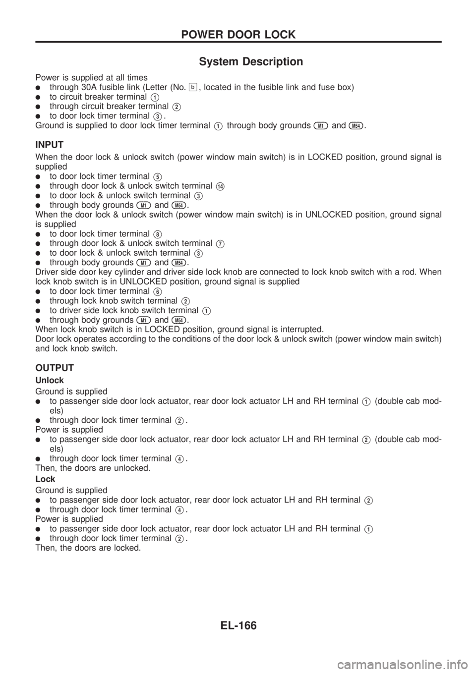
System Description
Power is supplied at all times
lthrough 30A fusible link (Letter (No.b, located in the fusible link and fuse box)
lto circuit breaker terminalV1
lthrough circuit breaker terminalV2
lto door lock timer terminalV3.
Ground is supplied to door lock timer terminal
V1through body groundsM1andM54.
INPUT
When the door lock & unlock switch (power window main switch) is in LOCKED position, ground signal is
supplied
lto door lock timer terminalV5
lthrough door lock & unlock switch terminalV14
lto door lock & unlock switch terminalV3
lthrough body groundsM1andM54.
When the door lock & unlock switch (power window main switch) is in UNLOCKED position, ground signal
is supplied
lto door lock timer terminalV8
lthrough door lock & unlock switch terminalV7
lto door lock & unlock switch terminalV3
lthrough body groundsM1andM54.
Driver side door key cylinder and driver side lock knob are connected to lock knob switch with a rod. When
lock knob switch is in UNLOCKED position, ground signal is supplied
lto door lock timer terminalV6
lthrough lock knob switch terminalV2
lto driver side lock knob switch terminalV1
lthrough body groundsM1andM54.
When lock knob switch is in LOCKED position, ground signal is interrupted.
Door lock operates according to the conditions of the door lock & unlock switch (power window main switch)
and lock knob switch.
OUTPUT
Unlock
Ground is supplied
lto passenger side door lock actuator, rear door lock actuator LH and RH terminalV1(double cab mod-
els)
lthrough door lock timer terminalV2.
Power is supplied
lto passenger side door lock actuator, rear door lock actuator LH and RH terminalV2(double cab mod-
els)
lthrough door lock timer terminalV4.
Then, the doors are unlocked.
Lock
Ground is supplied
lto passenger side door lock actuator, rear door lock actuator LH and RH terminalV2
lthrough door lock timer terminalV4.
Power is supplied
lto passenger side door lock actuator, rear door lock actuator LH and RH terminalV1
lthrough door lock timer terminalV2.
Then, the doors are locked.
POWER DOOR LOCK
EL-166
Page 1465 of 1659
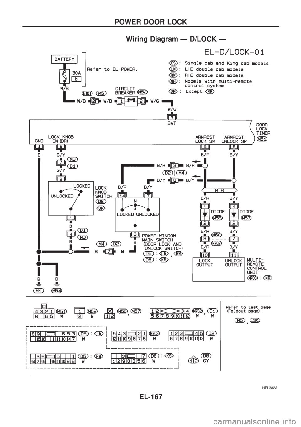
Wiring Diagram Ð D/LOCK Ð
HEL382A
POWER DOOR LOCK
EL-167
Page 1466 of 1659
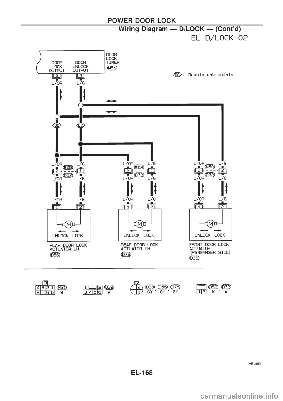
HEL962
POWER DOOR LOCK
Wiring Diagram Ð D/LOCK Ð (Cont'd)
EL-168
Page 1467 of 1659
Trouble Diagnosis
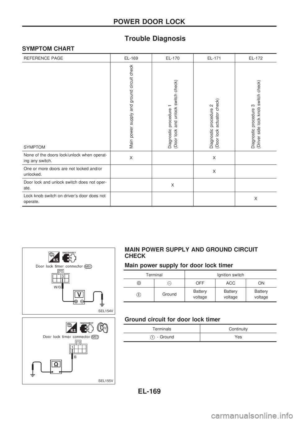
SYMPTOM CHART
REFERENCE PAGE EL-169 EL-170 EL-171 EL-172
SYMPTOM
Main power supply and ground circuit check
Diagnostic procedure 1
(Door lock and unlock switch check)
Diagnostic procedure 2
(Door lock actuator check)
Diagnostic procedure 3
(Driver side lock knob switch check)
None of the doors lock/unlock when operat-
ing any switch.XX
One or more doors are not locked and/or
unlocked.X
Door lock and unlock switch does not oper-
ate.X
Lock knob switch on driver's door does not
operate.X
MAIN POWER SUPPLY AND GROUND CIRCUIT
CHECK
Main power supply for door lock timer
Terminal Ignition switch
Å@OFF ACC ON
V3GroundBattery
voltageBattery
voltageBattery
voltage
Ground circuit for door lock timer
Terminals Continuity
V1- Ground Yes
SEL154V
SEL155V
POWER DOOR LOCK
EL-169
Page 1468 of 1659
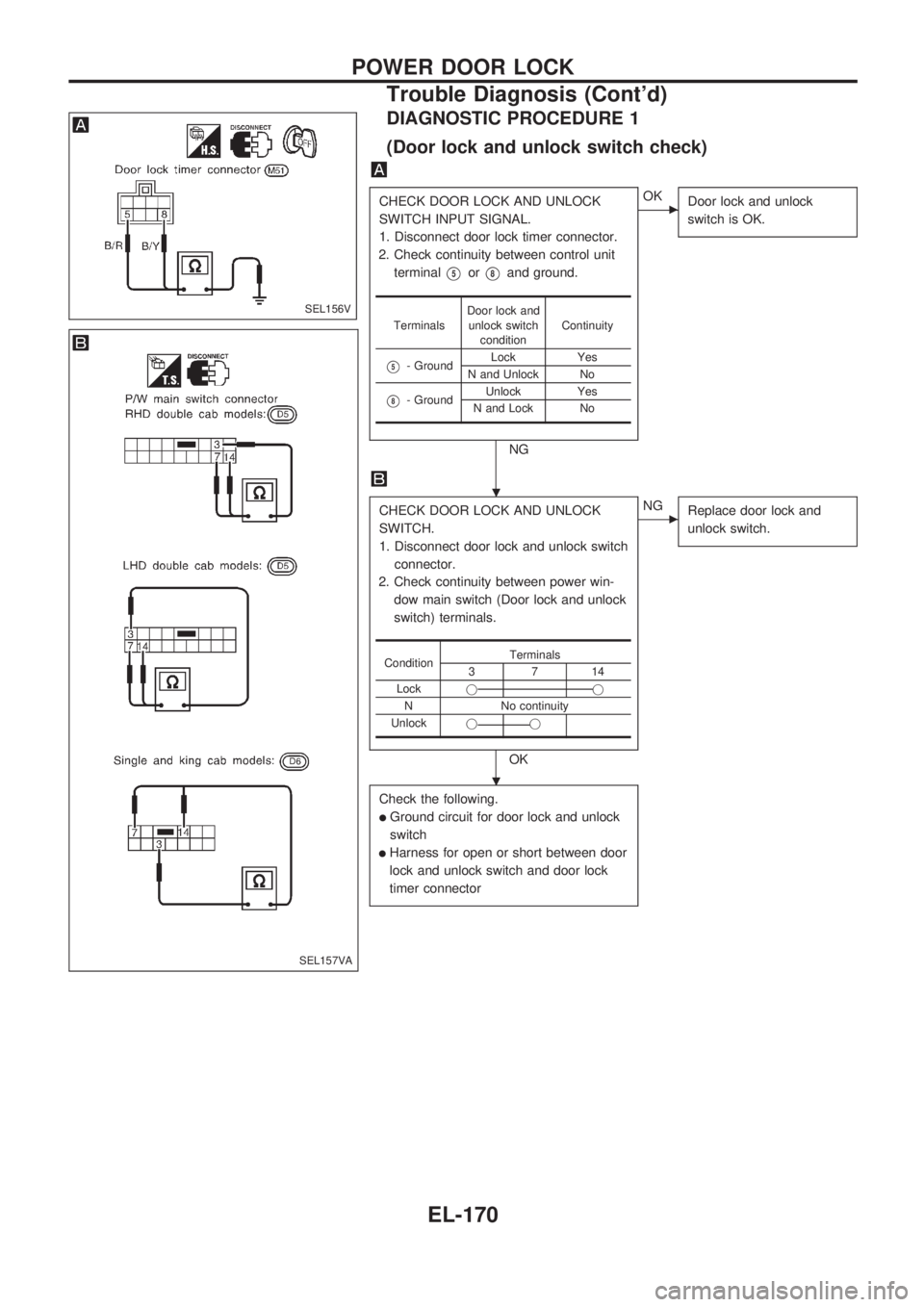
DIAGNOSTIC PROCEDURE 1
(Door lock and unlock switch check)
CHECK DOOR LOCK AND UNLOCK
SWITCH INPUT SIGNAL.
1. Disconnect door lock timer connector.
2. Check continuity between control unit
terminal
V5orV8and ground.
NG
cOK
Door lock and unlock
switch is OK.
CHECK DOOR LOCK AND UNLOCK
SWITCH.
1. Disconnect door lock and unlock switch
connector.
2. Check continuity between power win-
dow main switch (Door lock and unlock
switch) terminals.
OK
cNG
Replace door lock and
unlock switch.
Check the following.
lGround circuit for door lock and unlock
switch
lHarness for open or short between door
lock and unlock switch and door lock
timer connector
TerminalsDoor lock and
unlock switch
conditionContinuity
V5- GroundLock Yes
N and Unlock No
V8- GroundUnlock Yes
N and Lock No
ConditionTerminals
3714
Lockjj
N No continuity
Unlockjj
SEL156V
SEL157VA
.
.
POWER DOOR LOCK
Trouble Diagnosis (Cont'd)
EL-170
Page 1469 of 1659
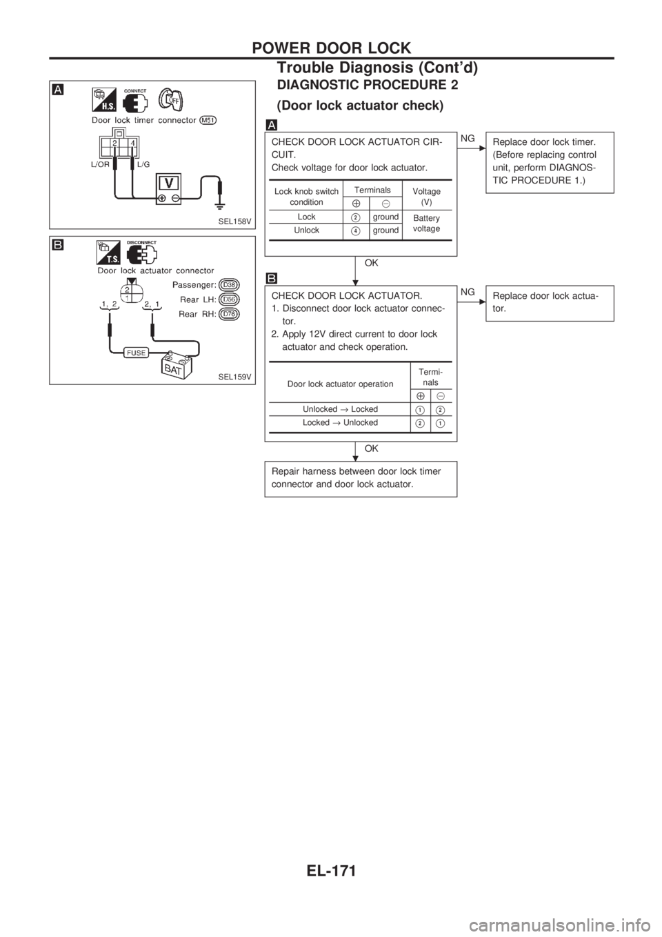
DIAGNOSTIC PROCEDURE 2
(Door lock actuator check)
CHECK DOOR LOCK ACTUATOR CIR-
CUIT.
Check voltage for door lock actuator.
OK
cNG
Replace door lock timer.
(Before replacing control
unit, perform DIAGNOS-
TIC PROCEDURE 1.)
CHECK DOOR LOCK ACTUATOR.
1. Disconnect door lock actuator connec-
tor.
2. Apply 12V direct current to door lock
actuator and check operation.
OK
cNG
Replace door lock actua-
tor.
Repair harness between door lock timer
connector and door lock actuator.
Lock knob switch
conditionTerminals
Voltage
(V)
Å@
Lock
V2ground
Battery
voltage
Unlock
V4ground
Door lock actuator operationTermi-
nals
Å@
Unlocked®Locked
V1V2
Locked®UnlockedV2V1
SEL158V
SEL159V
.
.
POWER DOOR LOCK
Trouble Diagnosis (Cont'd)
EL-171
Page 1470 of 1659
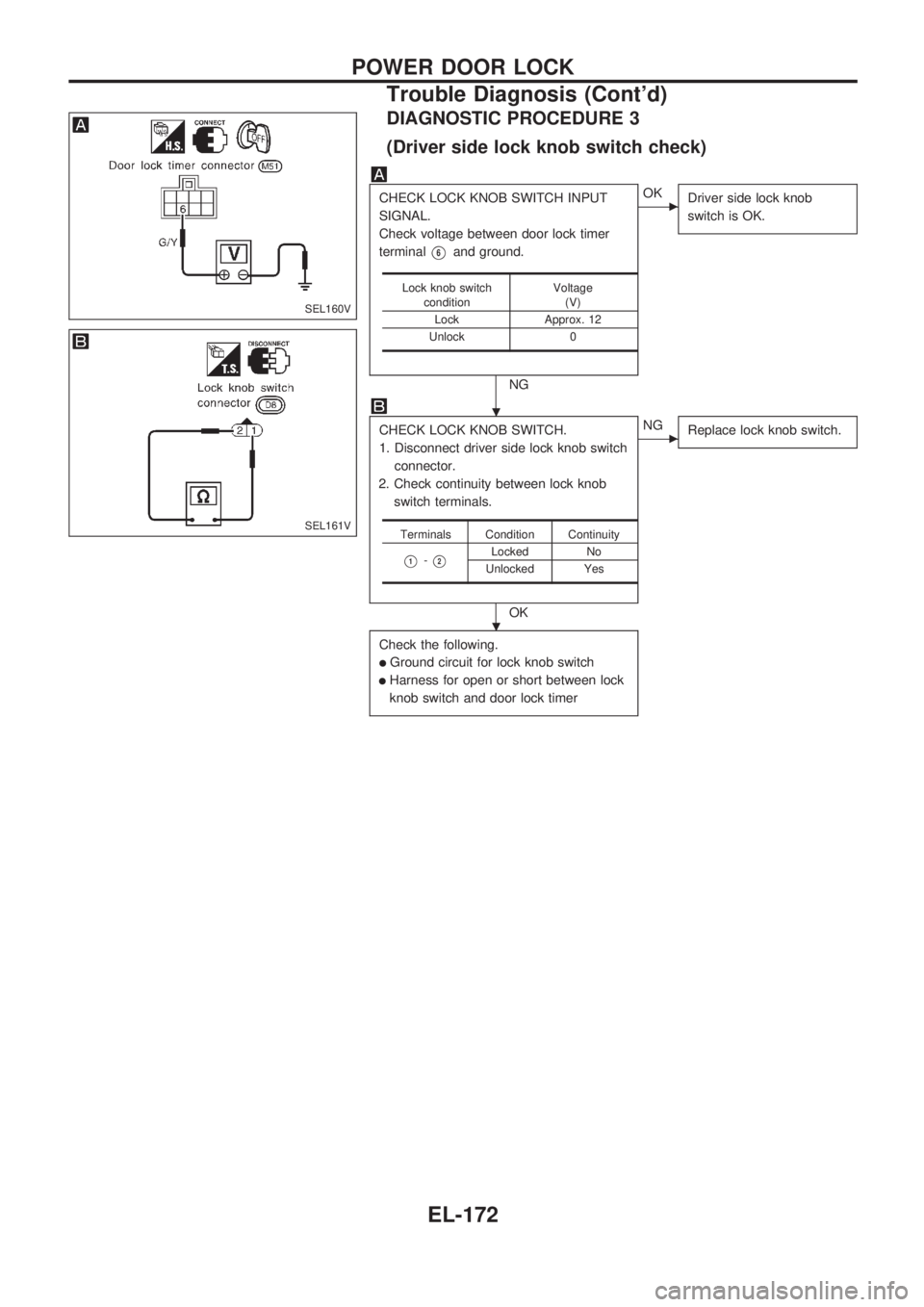
DIAGNOSTIC PROCEDURE 3
(Driver side lock knob switch check)
CHECK LOCK KNOB SWITCH INPUT
SIGNAL.
Check voltage between door lock timer
terminal
V6and ground.
NG
cOK
Driver side lock knob
switch is OK.
CHECK LOCK KNOB SWITCH.
1. Disconnect driver side lock knob switch
connector.
2. Check continuity between lock knob
switch terminals.
OK
cNG
Replace lock knob switch.
Check the following.
lGround circuit for lock knob switch
lHarness for open or short between lock
knob switch and door lock timer
Lock knob switch
conditionVoltage
(V)
Lock Approx. 12
Unlock 0
Terminals Condition Continuity
V1-V2Locked No
Unlocked Yes
SEL160V
SEL161V
.
.
POWER DOOR LOCK
Trouble Diagnosis (Cont'd)
EL-172
Trending: wiper fluid, engine, power steering, fuel filter location, timing belt, tire type, sensor
