NISSAN PICK-UP 1998 Repair Manual
PICK-UP 1998
NISSAN
NISSAN
https://www.carmanualsonline.info/img/5/57374/w960_57374-0.png
NISSAN PICK-UP 1998 Repair Manual
Trending: tow, ABS, airbag off, change key battery, horn, washer fluid, fuel cap release
Page 1431 of 1659
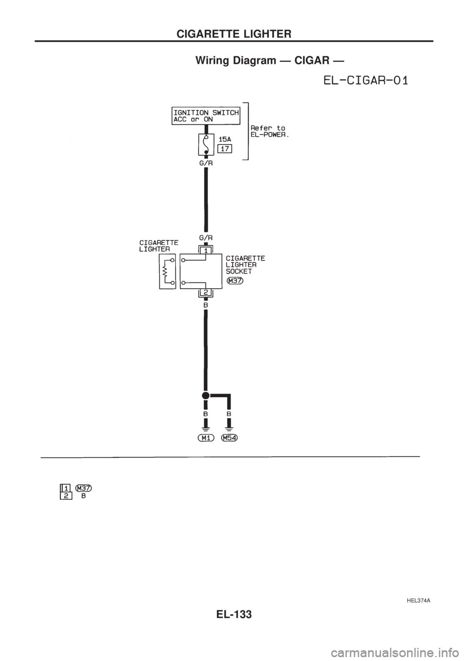
Wiring Diagram Ð CIGAR Ð
HEL374A
CIGARETTE LIGHTER
EL-133
Page 1432 of 1659
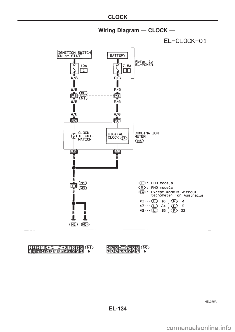
Wiring Diagram Ð CLOCK Ð
HEL375A
CLOCK
EL-134
Page 1433 of 1659
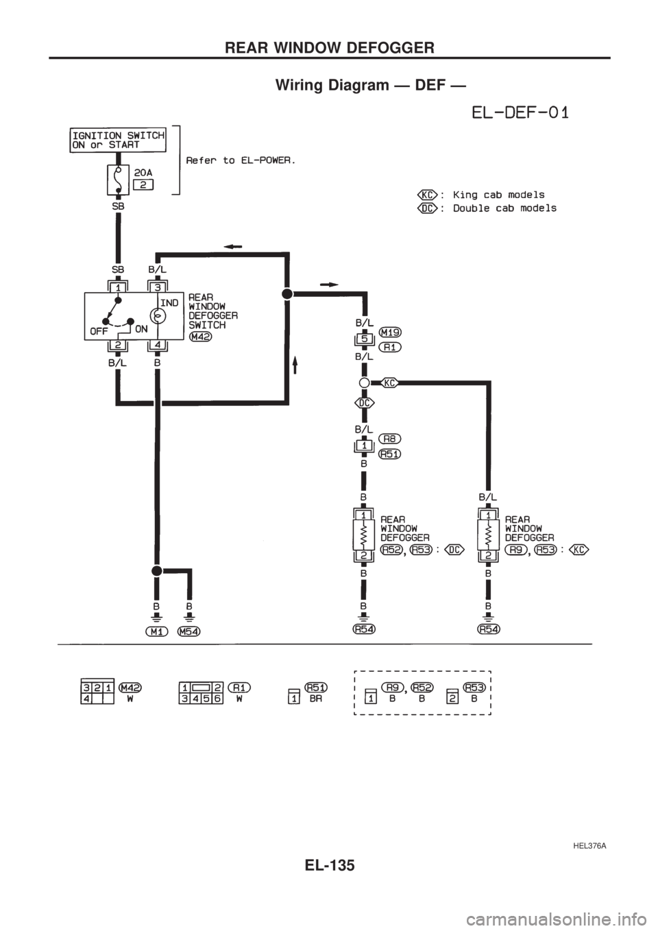
Wiring Diagram Ð DEF Ð
HEL376A
REAR WINDOW DEFOGGER
EL-135
Page 1434 of 1659
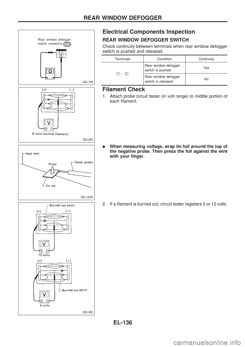
Electrical Components Inspection
REAR WINDOW DEFOGGER SWITCH
Check continuity between terminals when rear window defogger
switch is pushed and released.
Terminals Condition Continuity
V1-V2
Rear window defogger
switch is pushedYes
Rear window defogger
switch is releasedNo
Filament Check
1. Attach probe circuit tester (in volt range) to middle portion of
each filament.
lWhen measuring voltage, wrap tin foil around the top of
the negative probe. Then press the foil against the wire
with your finger.
2. If a filament is burned out, circuit tester registers 0 or 12 volts.
GEL195
SEL263
SEL122R
SEL265
REAR WINDOW DEFOGGER
EL-136
Page 1435 of 1659
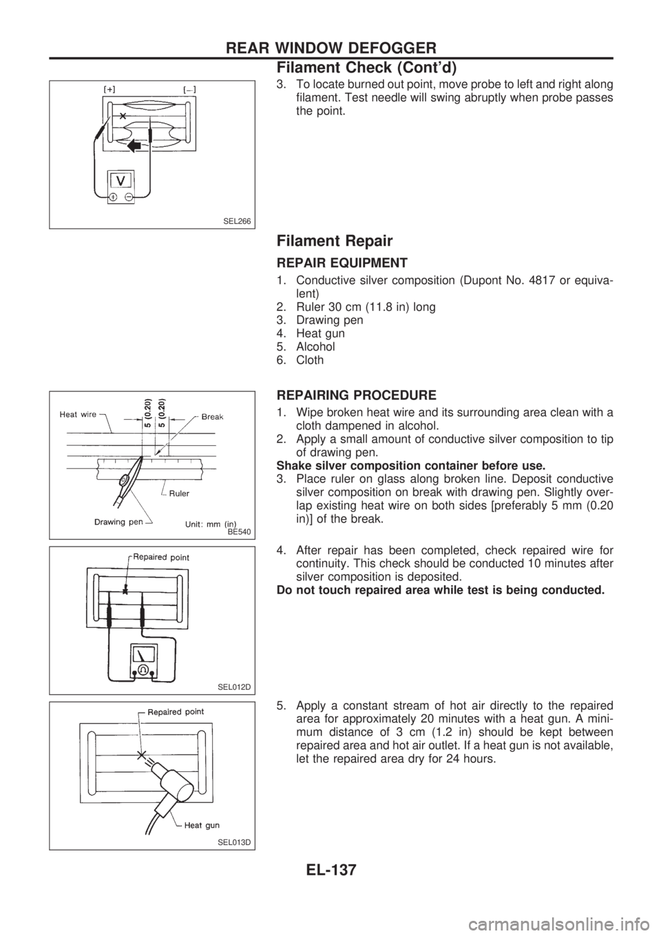
3. To locate burned out point, move probe to left and right along
filament. Test needle will swing abruptly when probe passes
the point.
Filament Repair
REPAIR EQUIPMENT
1. Conductive silver composition (Dupont No. 4817 or equiva-
lent)
2. Ruler 30 cm (11.8 in) long
3. Drawing pen
4. Heat gun
5. Alcohol
6. Cloth
REPAIRING PROCEDURE
1. Wipe broken heat wire and its surrounding area clean with a
cloth dampened in alcohol.
2. Apply a small amount of conductive silver composition to tip
of drawing pen.
Shake silver composition container before use.
3. Place ruler on glass along broken line. Deposit conductive
silver composition on break with drawing pen. Slightly over-
lap existing heat wire on both sides [preferably 5 mm (0.20
in)] of the break.
4. After repair has been completed, check repaired wire for
continuity. This check should be conducted 10 minutes after
silver composition is deposited.
Do not touch repaired area while test is being conducted.
5. Apply a constant stream of hot air directly to the repaired
area for approximately 20 minutes with a heat gun. A mini-
mum distance of 3 cm (1.2 in) should be kept between
repaired area and hot air outlet. If a heat gun is not available,
let the repaired area dry for 24 hours.
SEL266
BE540
SEL012D
SEL013D
REAR WINDOW DEFOGGER
Filament Check (Cont'd)
EL-137
Page 1436 of 1659
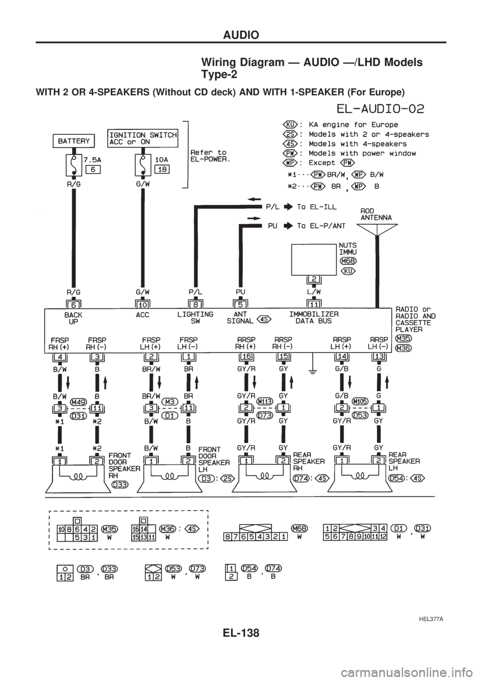
Wiring Diagram Ð AUDIO Ð/LHD Models
Type-2
WITH 2 OR 4-SPEAKERS (Without CD deck) AND WITH 1-SPEAKER (For Europe)
HEL377A
AUDIO
EL-138
Page 1437 of 1659
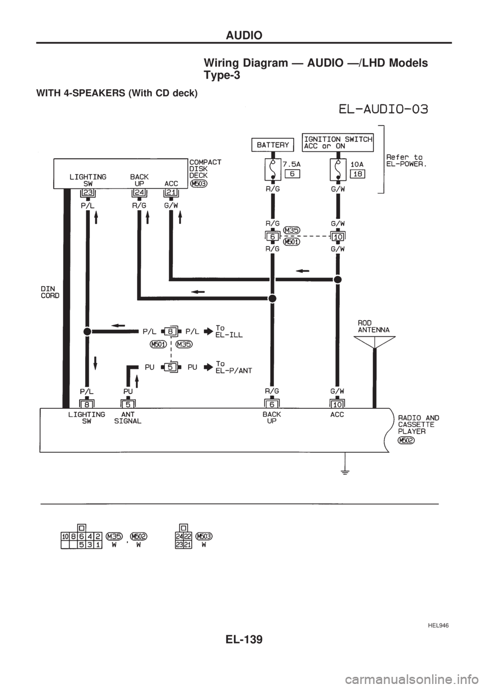
Wiring Diagram Ð AUDIO Ð/LHD Models
Type-3
WITH 4-SPEAKERS (With CD deck)
HEL946
AUDIO
EL-139
Page 1438 of 1659
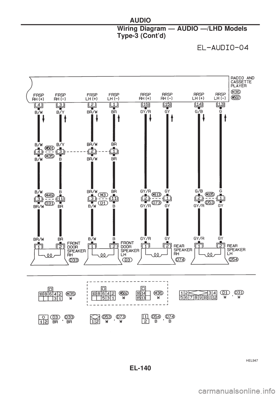
HEL947
AUDIO
Wiring Diagram Ð AUDIO Ð/LHD Models
Type-3 (Cont'd)
EL-140
Page 1439 of 1659
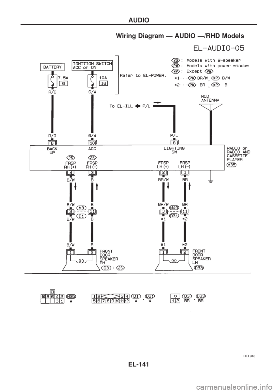
Wiring Diagram Ð AUDIO Ð/RHD Models
HEL948
AUDIO
EL-141
Page 1440 of 1659
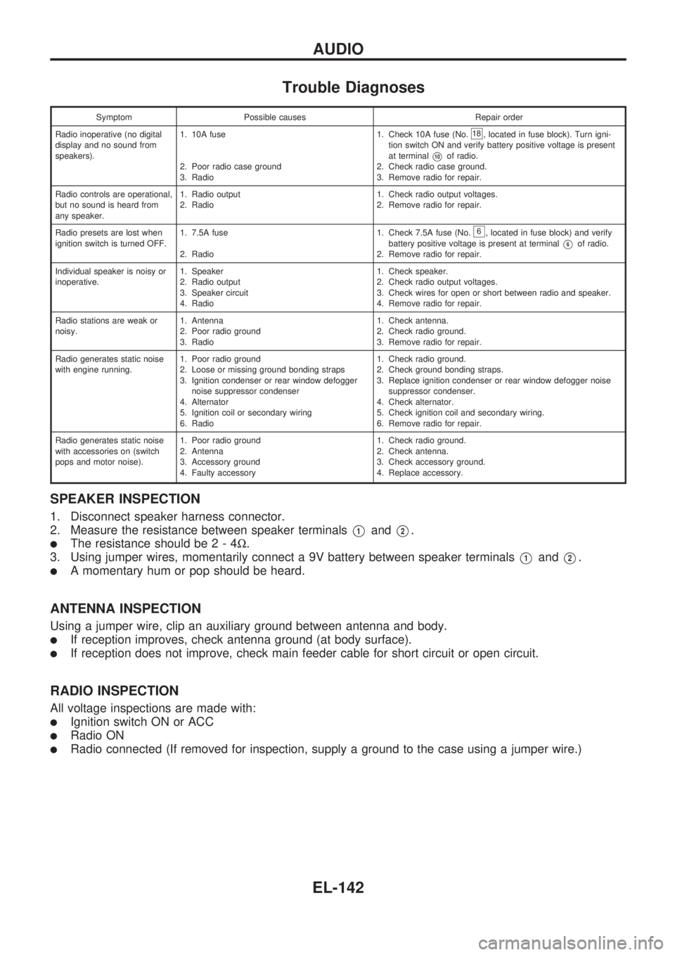
Trouble Diagnoses
Symptom Possible causes Repair order
Radio inoperative (no digital
display and no sound from
speakers).1. 10A fuse
2. Poor radio case ground
3. Radio1. Check 10A fuse (No.
18, located in fuse block). Turn igni-
tion switch ON and verify battery positive voltage is present
at terminal
V10of radio.
2. Check radio case ground.
3. Remove radio for repair.
Radio controls are operational,
but no sound is heard from
any speaker.1. Radio output
2. Radio1. Check radio output voltages.
2. Remove radio for repair.
Radio presets are lost when
ignition switch is turned OFF.1. 7.5A fuse
2. Radio1. Check 7.5A fuse (No.
6, located in fuse block) and verify
battery positive voltage is present at terminal
V6of radio.
2. Remove radio for repair.
Individual speaker is noisy or
inoperative.1. Speaker
2. Radio output
3. Speaker circuit
4. Radio1. Check speaker.
2. Check radio output voltages.
3. Check wires for open or short between radio and speaker.
4. Remove radio for repair.
Radio stations are weak or
noisy.1. Antenna
2. Poor radio ground
3. Radio1. Check antenna.
2. Check radio ground.
3. Remove radio for repair.
Radio generates static noise
with engine running.1. Poor radio ground
2. Loose or missing ground bonding straps
3. Ignition condenser or rear window defogger
noise suppressor condenser
4. Alternator
5. Ignition coil or secondary wiring
6. Radio1. Check radio ground.
2. Check ground bonding straps.
3. Replace ignition condenser or rear window defogger noise
suppressor condenser.
4. Check alternator.
5. Check ignition coil and secondary wiring.
6. Remove radio for repair.
Radio generates static noise
with accessories on (switch
pops and motor noise).1. Poor radio ground
2. Antenna
3. Accessory ground
4. Faulty accessory1. Check radio ground.
2. Check antenna.
3. Check accessory ground.
4. Replace accessory.
SPEAKER INSPECTION
1. Disconnect speaker harness connector.
2. Measure the resistance between speaker terminals
V1andV2.
lThe resistance should be2-4W.
3. Using jumper wires, momentarily connect a 9V battery between speaker terminals
V1andV2.
lA momentary hum or pop should be heard.
ANTENNA INSPECTION
Using a jumper wire, clip an auxiliary ground between antenna and body.
lIf reception improves, check antenna ground (at body surface).
lIf reception does not improve, check main feeder cable for short circuit or open circuit.
RADIO INSPECTION
All voltage inspections are made with:
lIgnition switch ON or ACC
lRadio ON
lRadio connected (If removed for inspection, supply a ground to the case using a jumper wire.)
AUDIO
EL-142
Trending: spark plugs, radio controls, wiper size, fuse box, tow, air condition, steering
