NISSAN PICK-UP 1998 Repair Manual
PICK-UP 1998
NISSAN
NISSAN
https://www.carmanualsonline.info/img/5/57374/w960_57374-0.png
NISSAN PICK-UP 1998 Repair Manual
Trending: radiator, center console, radiator cap, coolant reservoir, clock setting, battery replacement, air condition
Page 371 of 1659
Engine revolution sensor
1. Disconnect engine revolution sensor harness connector.
2. Check resistance between terminals
V1andV2.
Resistance: Approximately 1.6 kW[at 25ÉC (77ÉF)]
If NG, replace sensor.
Potentiometer
1. Disconnect potentiometer harness connector.
2. Make sure that resistance between terminals
V2andV3
changes when accelerator operated.
Accelerator pedal condition Resistance kW[at 20ÉC (68ÉF)]
Completely released Approximately 0.7
Partially depressed 0.7 - 5
Completely depressed Approximately 5
If NG, replace potentiometer.
Atmospheric pressure sensor
This sensor is inside ECM and not replaceable.
EGR system should not operate under atmospheric pressure
below 90.0 kPa (900 mbar, 675 mmHg, 26.57 inHg).
Engine coolant temperature sensor
Refer to ``Component Inspection'' in ``QUICK-GLOW SYSTEM'',
EC-209.
DEC031
DEC032
EGR SYSTEMTD
Component Inspection (Cont'd)
EC-219
Page 372 of 1659
Description
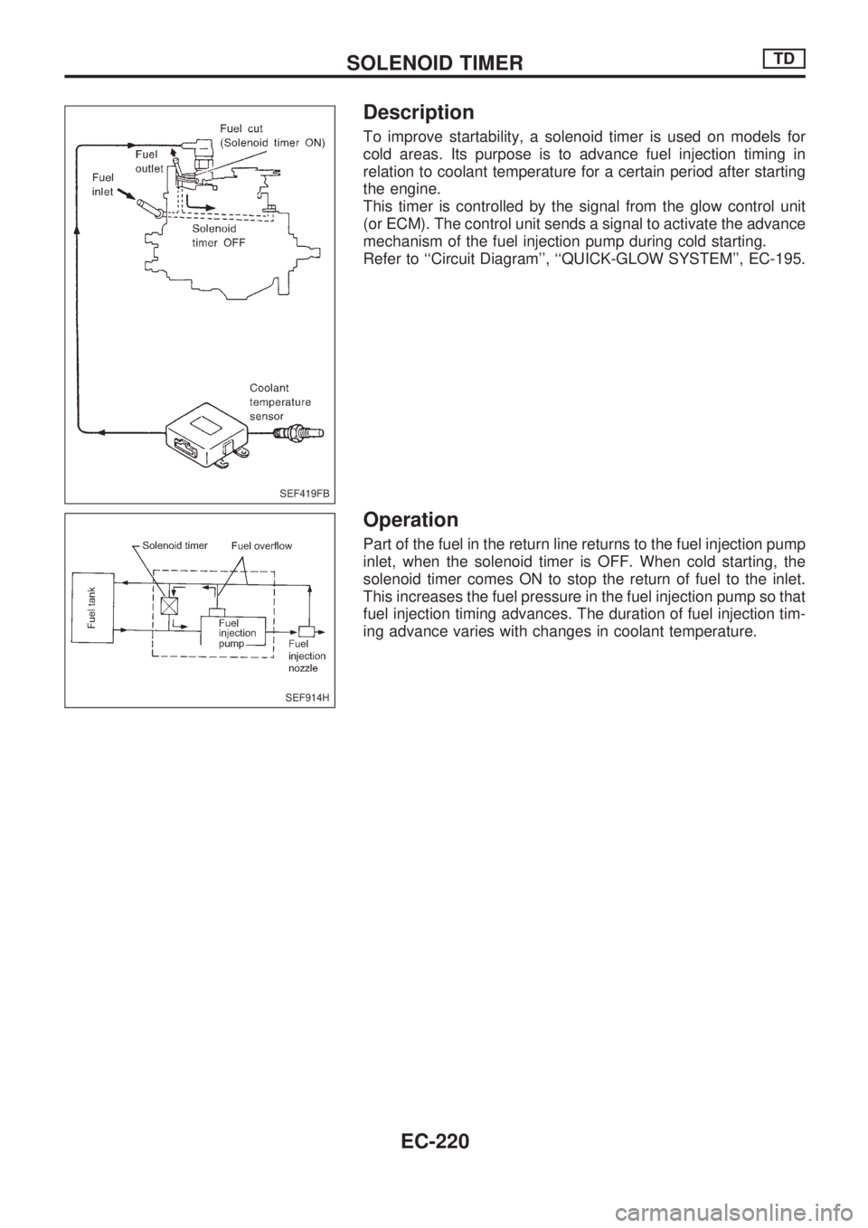
To improve startability, a solenoid timer is used on models for
cold areas. Its purpose is to advance fuel injection timing in
relation to coolant temperature for a certain period after starting
the engine.
This timer is controlled by the signal from the glow control unit
(or ECM). The control unit sends a signal to activate the advance
mechanism of the fuel injection pump during cold starting.
Refer to ``Circuit Diagram'', ``QUICK-GLOW SYSTEM'', EC-195.
Operation
Part of the fuel in the return line returns to the fuel injection pump
inlet, when the solenoid timer is OFF. When cold starting, the
solenoid timer comes ON to stop the return of fuel to the inlet.
This increases the fuel pressure in the fuel injection pump so that
fuel injection timing advances. The duration of fuel injection tim-
ing advance varies with changes in coolant temperature.
SEF419FB
SEF914H
SOLENOID TIMERTD
EC-220
Page 373 of 1659
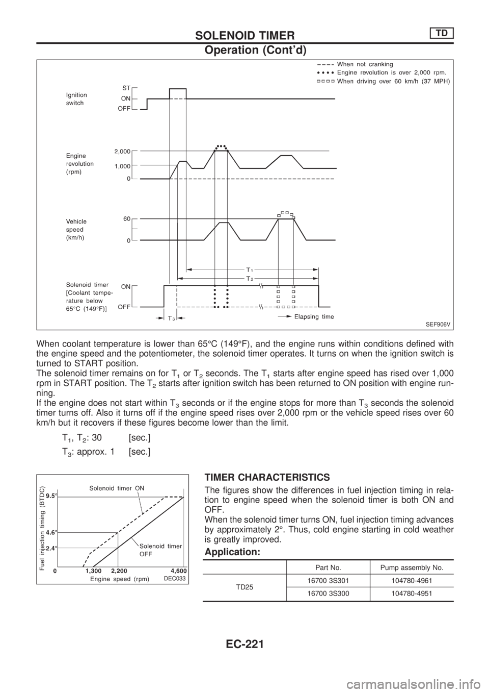
When coolant temperature is lower than 65ÉC (149ÉF), and the engine runs within conditions defined with
the engine speed and the potentiometer, the solenoid timer operates. It turns on when the ignition switch is
turned to START position.
The solenoid timer remains on for T
1or T2seconds. The T1starts after engine speed has rised over 1,000
rpm in START position. The T
2starts after ignition switch has been returned to ON position with engine run-
ning.
If the engine does not start within T
3seconds or if the engine stops for more than T3seconds the solenoid
timer turns off. Also it turns off if the engine speed rises over 2,000 rpm or the vehicle speed rises over 60
km/h but it recovers if these figures become lower than the limit.
T1,T2: 30 [sec.]
T
3: approx. 1 [sec.]
TIMER CHARACTERISTICS
The figures show the differences in fuel injection timing in rela-
tion to engine speed when the solenoid timer is both ON and
OFF.
When the solenoid timer turns ON, fuel injection timing advances
by approximately 2É. Thus, cold engine starting in cold weather
is greatly improved.
Application:
Part No. Pump assembly No.
TD2516700 3S301 104780-4961
16700 3S300 104780-4951
SEF906V
DEC033
.
SOLENOID TIMERTD
Operation (Cont'd)
EC-221
Page 374 of 1659
Wiring Diagram
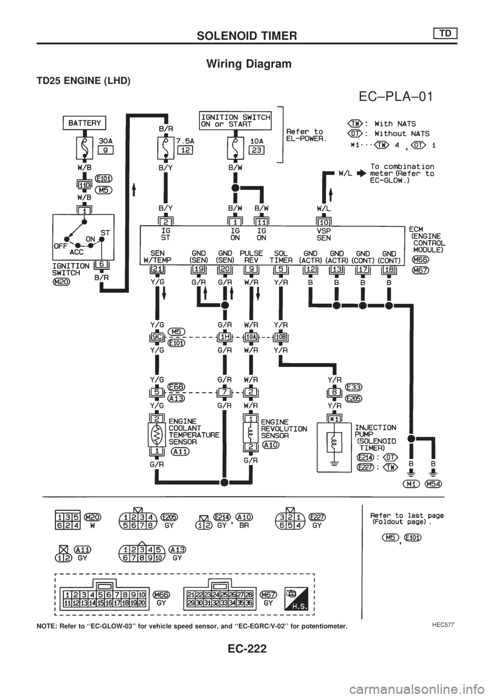
TD25 ENGINE (LHD)
NOTE: Refer to ``EC-GLOW-03'' for vehicle speed sensor, and ``EC-EGRC/V-02'' for potentiometer.HEC577
.
EC±PLA±01
SOLENOID TIMERTD
EC-222
Page 375 of 1659
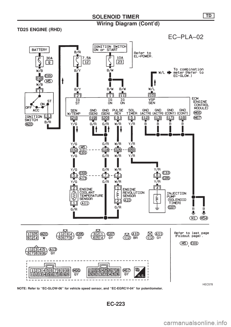
TD25 ENGINE (RHD)
NOTE: Refer to ``EC-GLOW-06'' for vehicle speed sensor, and ``EC-EGRC/V-04'' for potentiometer.
HEC578
.
EC±PLA±02
SOLENOID TIMERTD
Wiring Diagram (Cont'd)
EC-223
Page 376 of 1659
Inspection
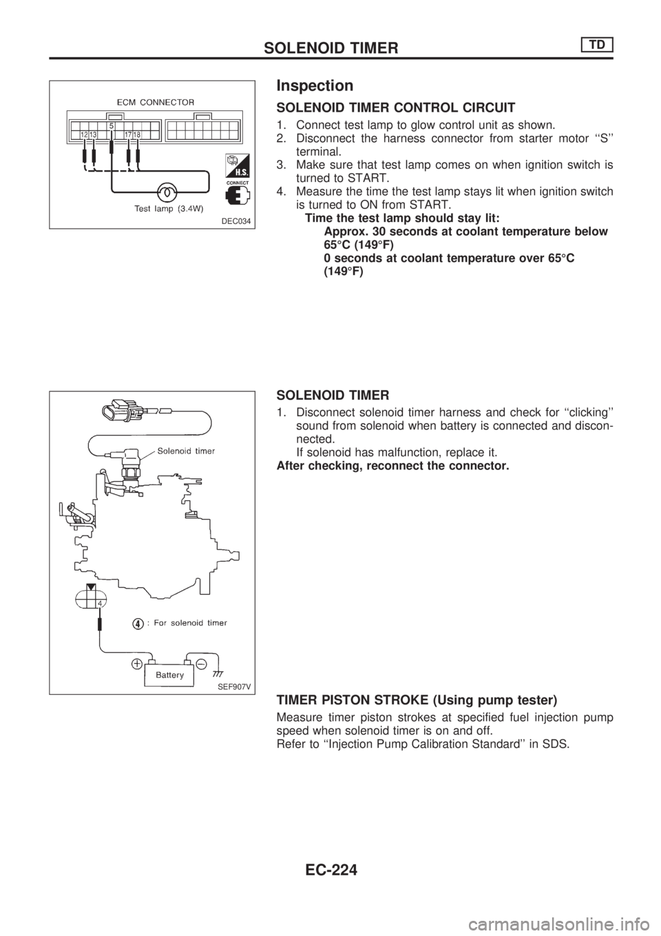
SOLENOID TIMER CONTROL CIRCUIT
1. Connect test lamp to glow control unit as shown.
2. Disconnect the harness connector from starter motor ``S''
terminal.
3. Make sure that test lamp comes on when ignition switch is
turned to START.
4. Measure the time the test lamp stays lit when ignition switch
is turned to ON from START.
Time the test lamp should stay lit:
Approx. 30 seconds at coolant temperature below
65ÉC (149ÉF)
0 seconds at coolant temperature over 65ÉC
(149ÉF)
SOLENOID TIMER
1. Disconnect solenoid timer harness and check for ``clicking''
sound from solenoid when battery is connected and discon-
nected.
If solenoid has malfunction, replace it.
After checking, reconnect the connector.
TIMER PISTON STROKE (Using pump tester)
Measure timer piston strokes at specified fuel injection pump
speed when solenoid timer is on and off.
Refer to ``Injection Pump Calibration Standard'' in SDS.
DEC034
.
SEF907V
SOLENOID TIMERTD
EC-224
Page 377 of 1659
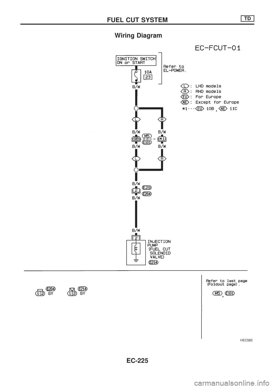
Wiring Diagram
HEC583
FUEL CUT SYSTEMTD
EC-225
Page 378 of 1659
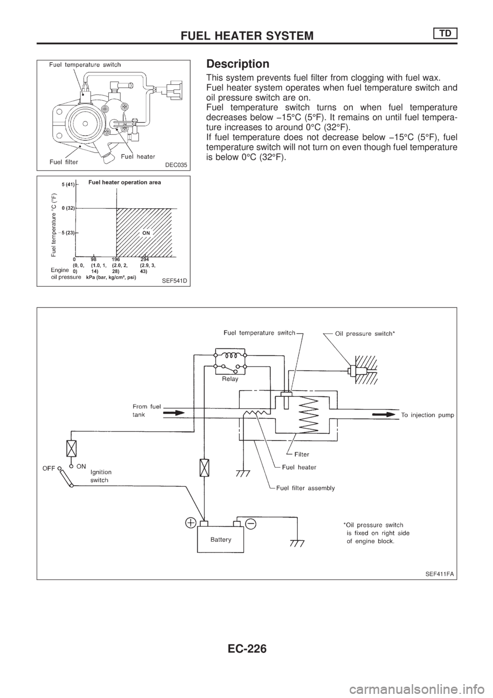
Description
This system prevents fuel filter from clogging with fuel wax.
Fuel heater system operates when fuel temperature switch and
oil pressure switch are on.
Fuel temperature switch turns on when fuel temperature
decreases below þ15ÉC (5ÉF). It remains on until fuel tempera-
ture increases to around 0ÉC (32ÉF).
If fuel temperature does not decrease below þ15ÉC (5ÉF), fuel
temperature switch will not turn on even though fuel temperature
is below 0ÉC (32ÉF).
DEC035
SEF541D
SEF411FA
FUEL HEATER SYSTEMTD
EC-226
Page 379 of 1659
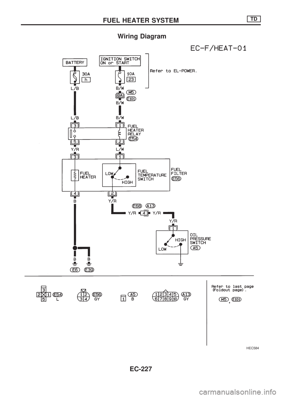
Wiring Diagram
HEC584
FUEL HEATER SYSTEMTD
EC-227
Page 380 of 1659
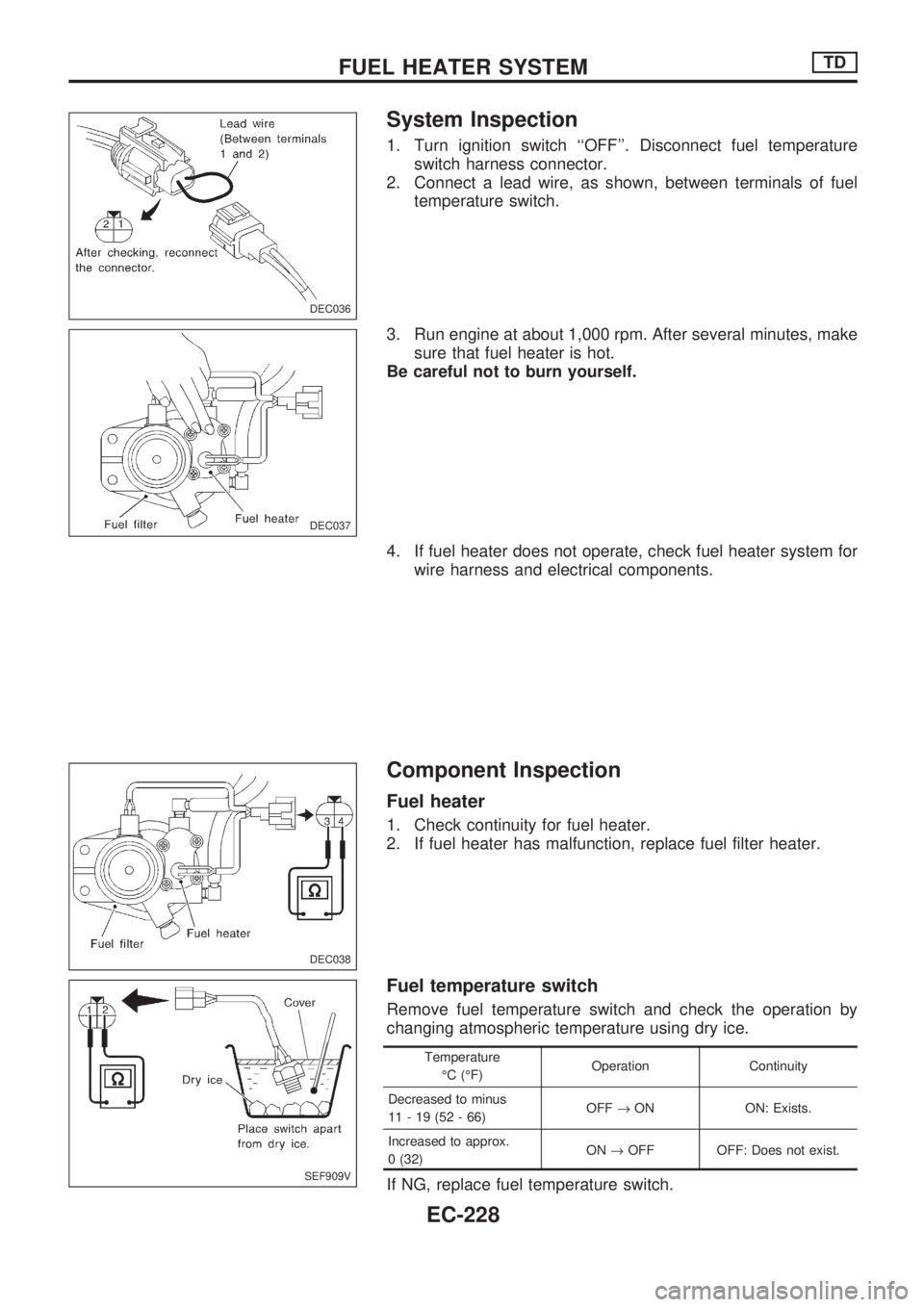
System Inspection
1. Turn ignition switch ``OFF''. Disconnect fuel temperature
switch harness connector.
2. Connect a lead wire, as shown, between terminals of fuel
temperature switch.
3. Run engine at about 1,000 rpm. After several minutes, make
sure that fuel heater is hot.
Be careful not to burn yourself.
4. If fuel heater does not operate, check fuel heater system for
wire harness and electrical components.
Component Inspection
Fuel heater
1. Check continuity for fuel heater.
2. If fuel heater has malfunction, replace fuel filter heater.
Fuel temperature switch
Remove fuel temperature switch and check the operation by
changing atmospheric temperature using dry ice.
Temperature
ÉC (ÉF)Operation Continuity
Decreased to minus
11-19(52-66)OFF®ON ON: Exists.
Increased to approx.
0 (32)ON®OFF OFF: Does not exist.
If NG, replace fuel temperature switch.
DEC036
DEC037
DEC038
SEF909V
FUEL HEATER SYSTEMTD
EC-228
Trending: drain bolt, belt, tire pressure, fuel pump, four wheel drive, oil level, oil
![NISSAN PICK-UP 1998 Repair Manual Engine revolution sensor
1. Disconnect engine revolution sensor harness connector.
2. Check resistance between terminals
V1andV2.
Resistance: Approximately 1.6 kW[at 25ÉC (77ÉF)]
If NG, replace sens NISSAN PICK-UP 1998 Repair Manual Engine revolution sensor
1. Disconnect engine revolution sensor harness connector.
2. Check resistance between terminals
V1andV2.
Resistance: Approximately 1.6 kW[at 25ÉC (77ÉF)]
If NG, replace sens](/img/5/57374/w960_57374-370.png)
