NISSAN PICK-UP 1998 Repair Manual
PICK-UP 1998
NISSAN
NISSAN
https://www.carmanualsonline.info/img/5/57374/w960_57374-0.png
NISSAN PICK-UP 1998 Repair Manual
Trending: manual transmission, automatic transmission fluid, spare tire, Ignition, oil filter, instrument cluster, warning
Page 341 of 1659
Assembly
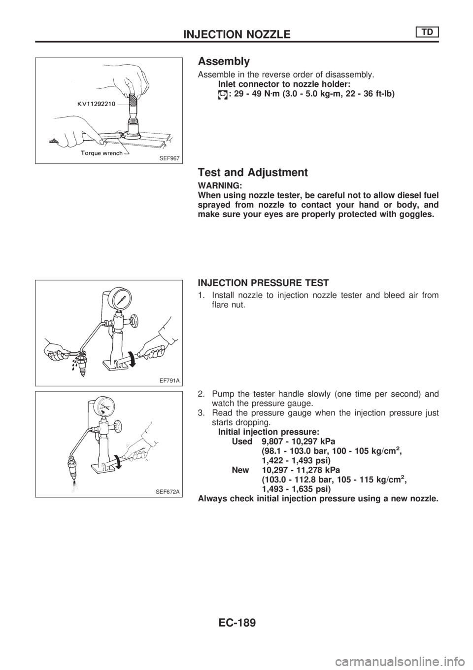
Assemble in the reverse order of disassembly.
Inlet connector to nozzle holder:
:29-49Nzm (3.0 - 5.0 kg-m, 22 - 36 ft-lb)
Test and Adjustment
WARNING:
When using nozzle tester, be careful not to allow diesel fuel
sprayed from nozzle to contact your hand or body, and
make sure your eyes are properly protected with goggles.
INJECTION PRESSURE TEST
1. Install nozzle to injection nozzle tester and bleed air from
flare nut.
2. Pump the tester handle slowly (one time per second) and
watch the pressure gauge.
3. Read the pressure gauge when the injection pressure just
starts dropping.
Initial injection pressure:
Used 9,807 - 10,297 kPa
(98.1 - 103.0 bar, 100 - 105 kg/cm
2,
1,422 - 1,493 psi)
New 10,297 - 11,278 kPa
(103.0 - 112.8 bar, 105 - 115 kg/cm
2,
1,493 - 1,635 psi)
Always check initial injection pressure using a new nozzle.
SEF967
EF791A
SEF672A
INJECTION NOZZLETD
EC-189
Page 342 of 1659
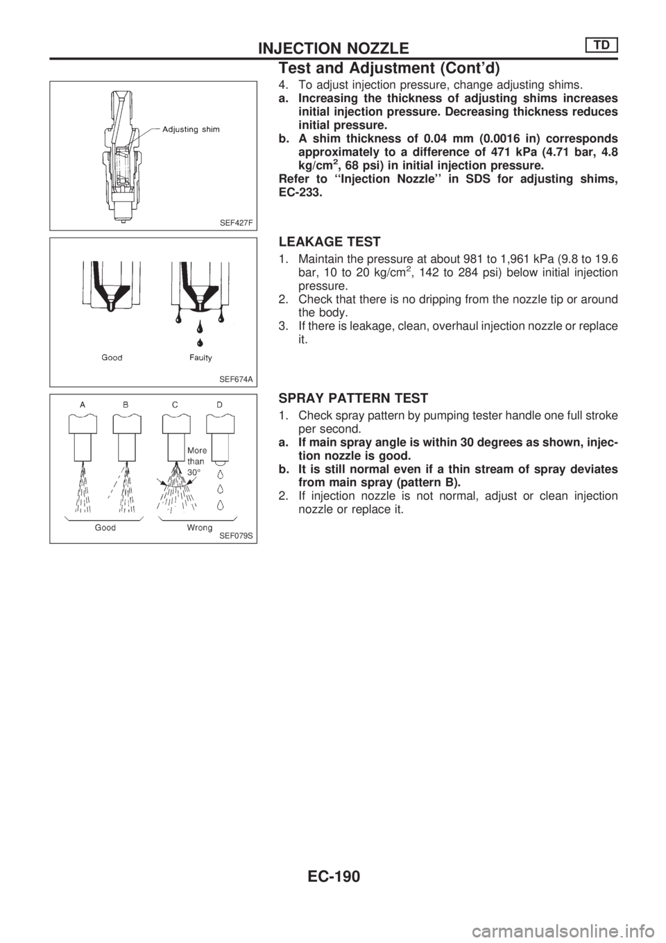
4. To adjust injection pressure, change adjusting shims.
a. Increasing the thickness of adjusting shims increases
initial injection pressure. Decreasing thickness reduces
initial pressure.
b. A shim thickness of 0.04 mm (0.0016 in) corresponds
approximately to a difference of 471 kPa (4.71 bar, 4.8
kg/cm
2, 68 psi) in initial injection pressure.
Refer to ``Injection Nozzle'' in SDS for adjusting shims,
EC-233.
LEAKAGE TEST
1. Maintain the pressure at about 981 to 1,961 kPa (9.8 to 19.6
bar, 10 to 20 kg/cm2, 142 to 284 psi) below initial injection
pressure.
2. Check that there is no dripping from the nozzle tip or around
the body.
3. If there is leakage, clean, overhaul injection nozzle or replace
it.
SPRAY PATTERN TEST
1. Check spray pattern by pumping tester handle one full stroke
per second.
a. If main spray angle is within 30 degrees as shown, injec-
tion nozzle is good.
b. It is still normal even if a thin stream of spray deviates
from main spray (pattern B).
2. If injection nozzle is not normal, adjust or clean injection
nozzle or replace it.
SEF427F
SEF674A
SEF079S
INJECTION NOZZLETD
Test and Adjustment (Cont'd)
EC-190
Page 343 of 1659
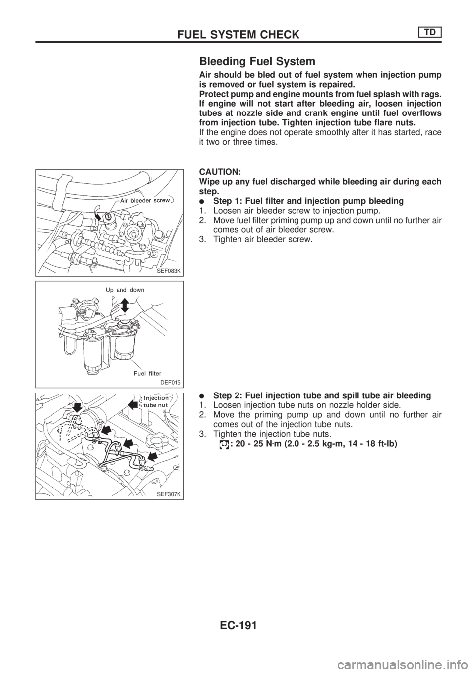
Bleeding Fuel System
Air should be bled out of fuel system when injection pump
is removed or fuel system is repaired.
Protect pump and engine mounts from fuel splash with rags.
If engine will not start after bleeding air, loosen injection
tubes at nozzle side and crank engine until fuel overflows
from injection tube. Tighten injection tube flare nuts.
If the engine does not operate smoothly after it has started, race
it two or three times.
CAUTION:
Wipe up any fuel discharged while bleeding air during each
step.
lStep 1: Fuel filter and injection pump bleeding
1. Loosen air bleeder screw to injection pump.
2. Move fuel filter priming pump up and down until no further air
comes out of air bleeder screw.
3. Tighten air bleeder screw.
lStep 2: Fuel injection tube and spill tube air bleeding
1. Loosen injection tube nuts on nozzle holder side.
2. Move the priming pump up and down until no further air
comes out of the injection tube nuts.
3. Tighten the injection tube nuts.
:20-25Nzm (2.0 - 2.5 kg-m, 14 - 18 ft-lb)
SEF083K
DEF015
SEF307K
FUEL SYSTEM CHECKTD
EC-191
Page 344 of 1659
Bleeding Fuel Filter
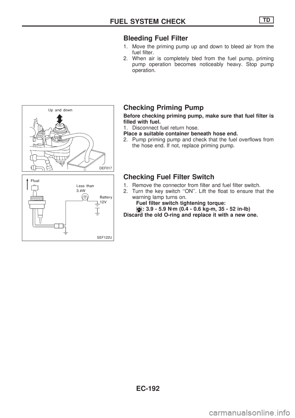
1. Move the priming pump up and down to bleed air from the
fuel filter.
2. When air is completely bled from the fuel pump, priming
pump operation becomes noticeably heavy. Stop pump
operation.
Checking Priming Pump
Before checking priming pump, make sure that fuel filter is
filled with fuel.
1. Disconnect fuel return hose.
Place a suitable container beneath hose end.
2. Pump priming pump and check that the fuel overflows from
the hose end. If not, replace priming pump.
Checking Fuel Filter Switch
1. Remove the connector from filter and fuel filter switch.
2. Turn the key switch ``ON''. Lift the float to ensure that the
warning lamp turns on.
Fuel filter switch tightening torque:
: 3.9 - 5.9 Nzm (0.4 - 0.6 kg-m, 35 - 52 in-lb)
Discard the old O-ring and replace it with a new one.
DEF017
SEF122U
FUEL SYSTEM CHECKTD
EC-192
Page 345 of 1659
Page 346 of 1659
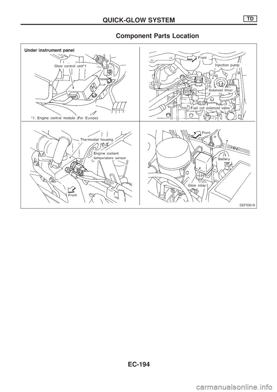
Component Parts Location
DEF030-N
QUICK-GLOW SYSTEMTD
EC-194
Page 347 of 1659
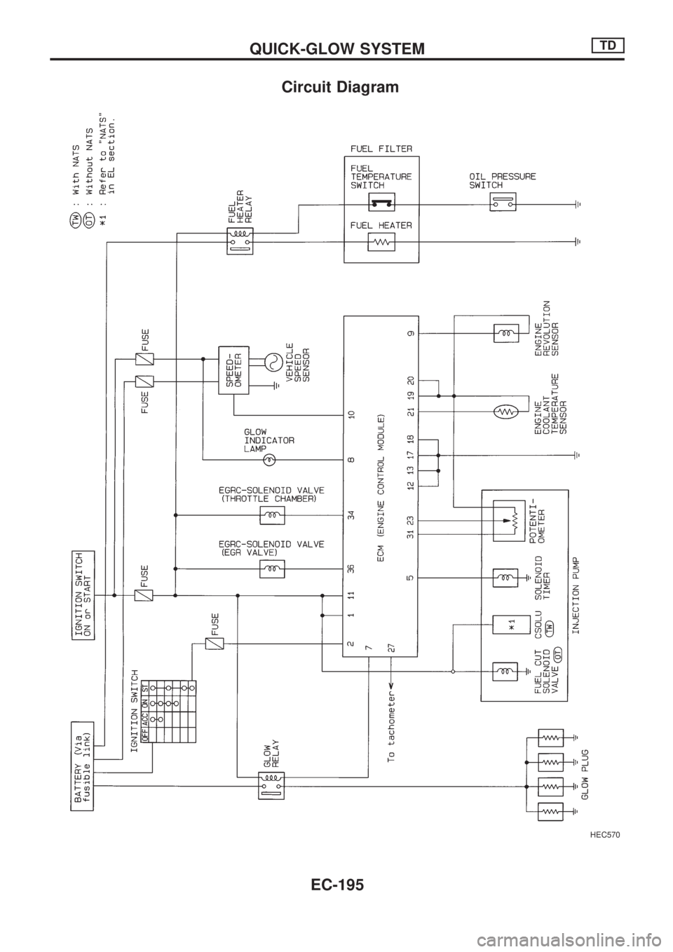
Circuit Diagram
HEC570
QUICK-GLOW SYSTEMTD
EC-195
Page 348 of 1659
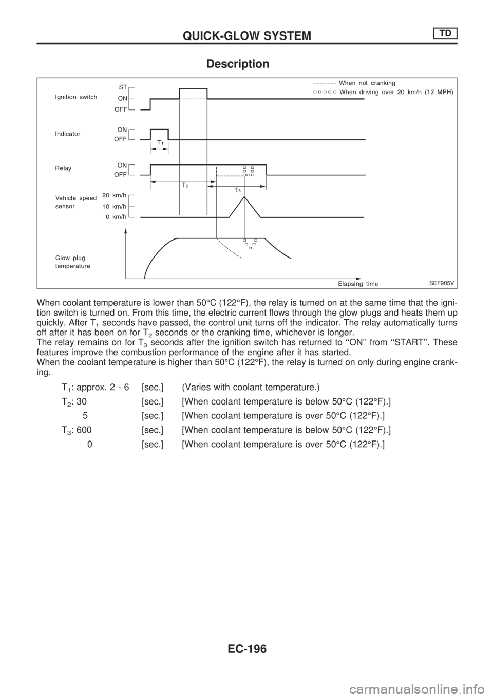
Description
When coolant temperature is lower than 50ÉC (122ÉF), the relay is turned on at the same time that the igni-
tion switch is turned on. From this time, the electric current flows through the glow plugs and heats them up
quickly. After T
1seconds have passed, the control unit turns off the indicator. The relay automatically turns
off after it has been on for T
2seconds or the cranking time, whichever is longer.
The relay remains on for T
3seconds after the ignition switch has returned to ``ON'' from ``START''. These
features improve the combustion performance of the engine after it has started.
When the coolant temperature is higher than 50ÉC (122ÉF), the relay is turned on only during engine crank-
ing.
T1: approx.2-6[sec.] (Varies with coolant temperature.)
T
2: 30 [sec.] [When coolant temperature is below 50ÉC (122ÉF).]
5 [sec.] [When coolant temperature is over 50ÉC (122ÉF).]
T
3: 600 [sec.] [When coolant temperature is below 50ÉC (122ÉF).]
0 [sec.] [When coolant temperature is over 50ÉC (122ÉF).]
SEF905V
QUICK-GLOW SYSTEMTD
EC-196
Page 349 of 1659
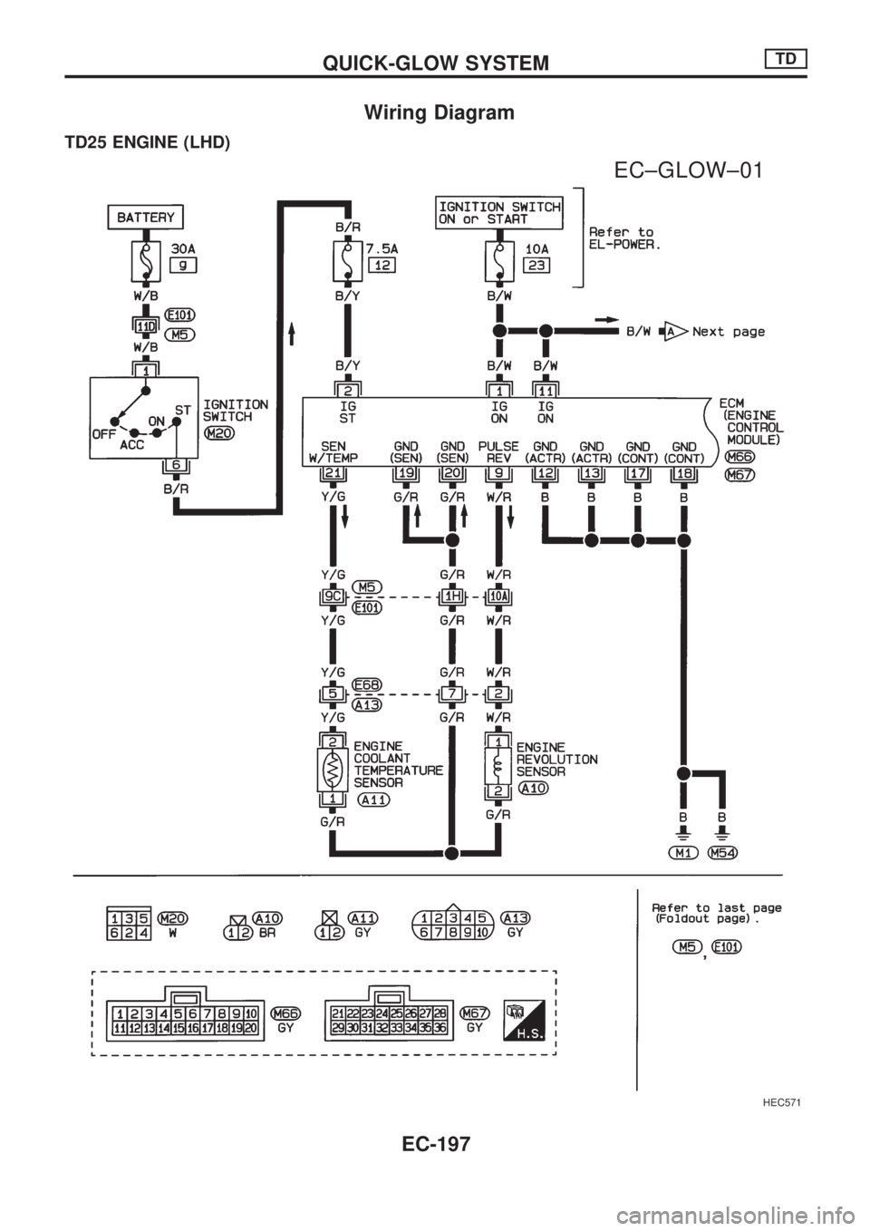
Wiring Diagram
TD25 ENGINE (LHD)
HEC571
.
EC±GLOW±01
QUICK-GLOW SYSTEMTD
EC-197
Page 350 of 1659
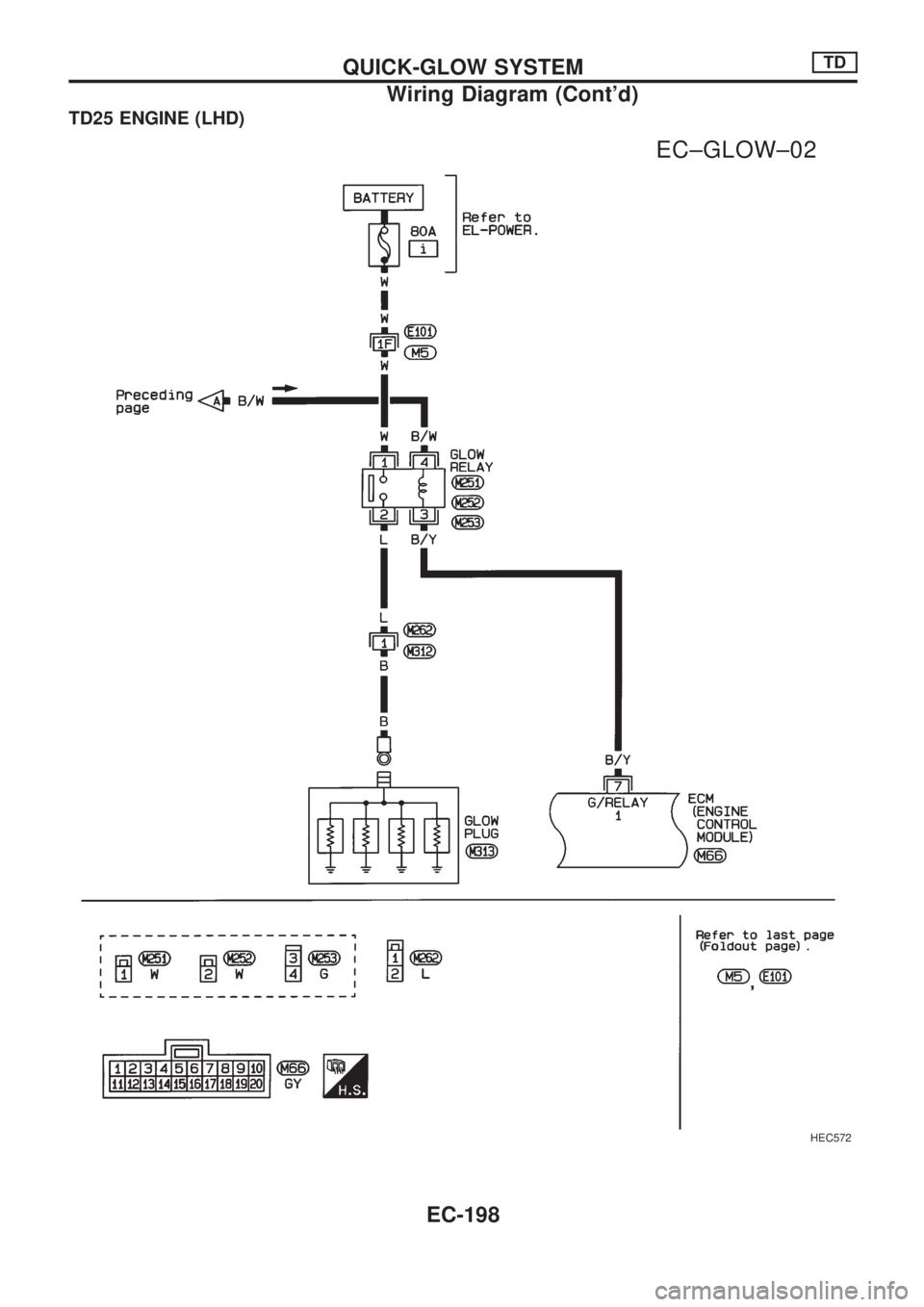
TD25 ENGINE (LHD)
HEC572
.
EC±GLOW±02
QUICK-GLOW SYSTEMTD
Wiring Diagram (Cont'd)
EC-198
Trending: clock setting, coolant level, instrument panel, alternator belt, flat tire, gas tank size, parking brake
