NISSAN PICK-UP 1998 Repair Manual
Manufacturer: NISSAN, Model Year: 1998, Model line: PICK-UP, Model: NISSAN PICK-UP 1998Pages: 1659, PDF Size: 53.39 MB
Page 331 of 1659
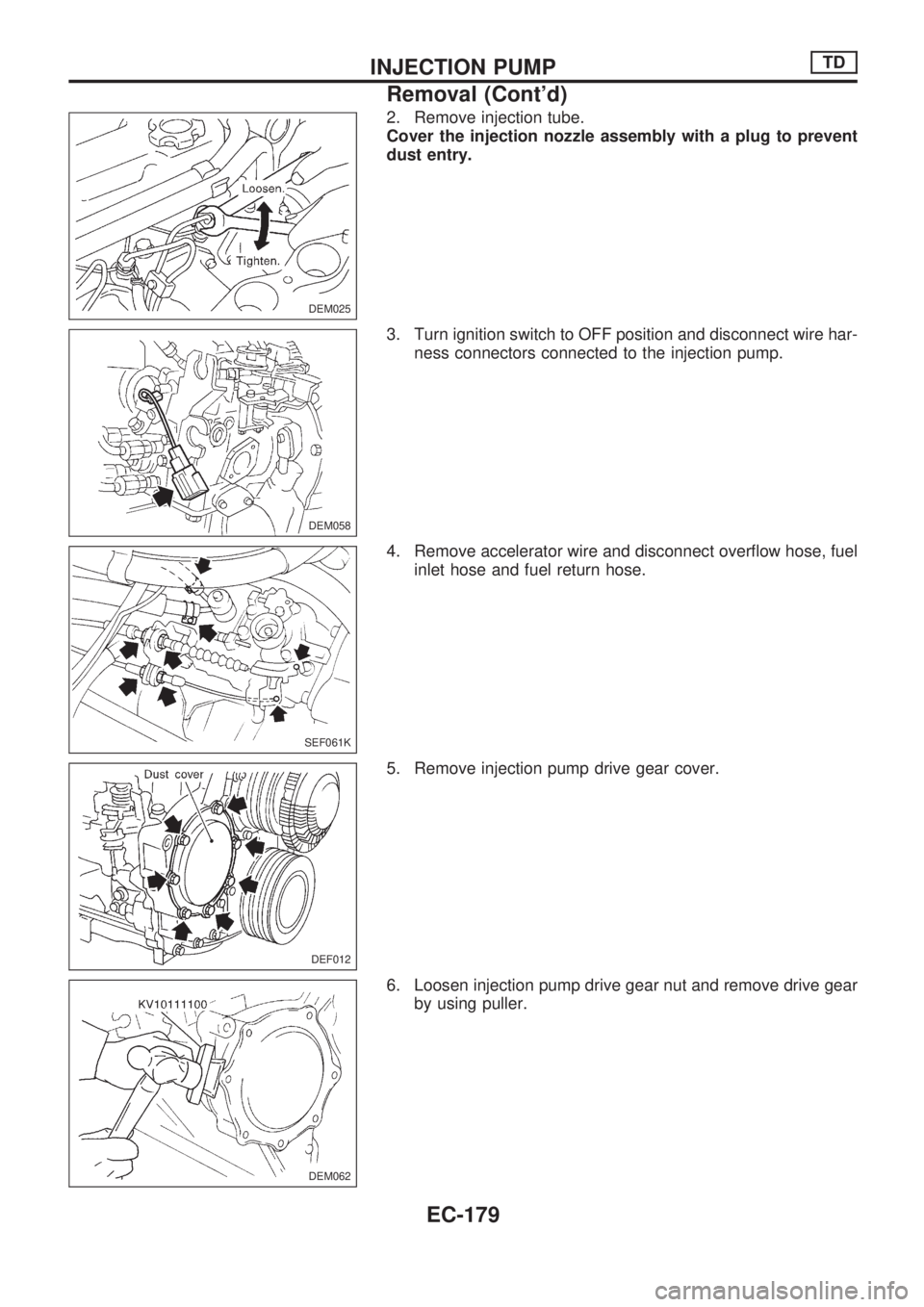
2. Remove injection tube.
Cover the injection nozzle assembly with a plug to prevent
dust entry.
3. Turn ignition switch to OFF position and disconnect wire har-
ness connectors connected to the injection pump.
4. Remove accelerator wire and disconnect overflow hose, fuel
inlet hose and fuel return hose.
5. Remove injection pump drive gear cover.
6. Loosen injection pump drive gear nut and remove drive gear
by using puller.
DEM025
DEM058
SEF061K
DEF012
DEM062
INJECTION PUMPTD
Removal (Cont'd)
EC-179
Page 332 of 1659
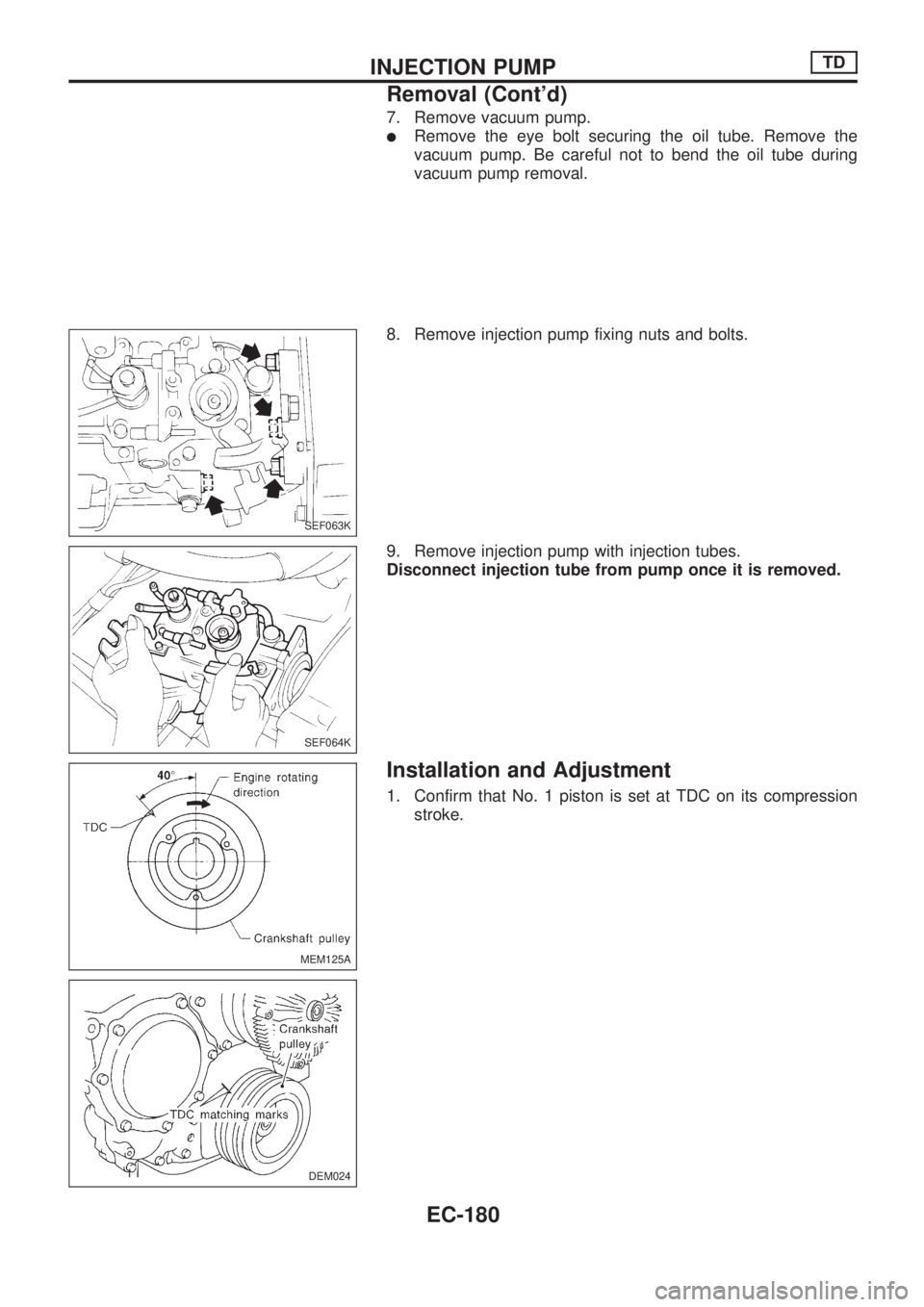
7. Remove vacuum pump.
lRemove the eye bolt securing the oil tube. Remove the
vacuum pump. Be careful not to bend the oil tube during
vacuum pump removal.
8. Remove injection pump fixing nuts and bolts.
9. Remove injection pump with injection tubes.
Disconnect injection tube from pump once it is removed.
Installation and Adjustment
1. Confirm that No. 1 piston is set at TDC on its compression
stroke.
SEF063K
SEF064K
MEM125A
DEM024
INJECTION PUMPTD
Removal (Cont'd)
EC-180
Page 333 of 1659
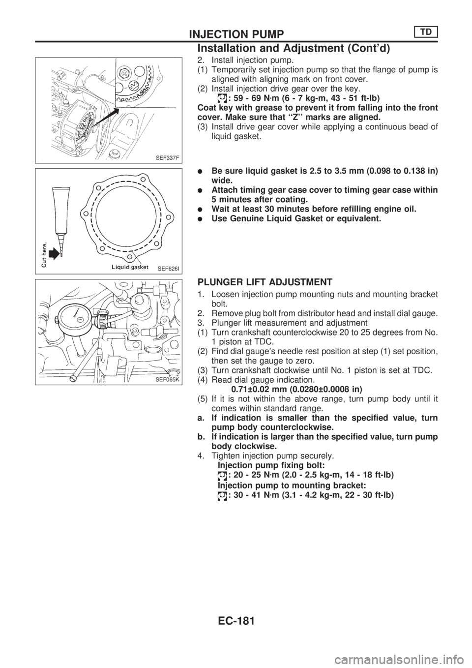
2. Install injection pump.
(1) Temporarily set injection pump so that the flange of pump is
aligned with aligning mark on front cover.
(2) Install injection drive gear over the key.
:59-69Nzm (6 - 7 kg-m, 43 - 51 ft-lb)
Coat key with grease to prevent it from falling into the front
cover. Make sure that ``Z'' marks are aligned.
(3) Install drive gear cover while applying a continuous bead of
liquid gasket.
lBe sure liquid gasket is 2.5 to 3.5 mm (0.098 to 0.138 in)
wide.
lAttach timing gear case cover to timing gear case within
5 minutes after coating.
lWait at least 30 minutes before refilling engine oil.
lUse Genuine Liquid Gasket or equivalent.
PLUNGER LIFT ADJUSTMENT
1. Loosen injection pump mounting nuts and mounting bracket
bolt.
2. Remove plug bolt from distributor head and install dial gauge.
3. Plunger lift measurement and adjustment
(1) Turn crankshaft counterclockwise 20 to 25 degrees from No.
1 piston at TDC.
(2) Find dial gauge's needle rest position at step (1) set position,
then set the gauge to zero.
(3) Turn crankshaft clockwise until No. 1 piston is set at TDC.
(4) Read dial gauge indication.
0.71 0.02 mm (0.0280 0.0008 in)
(5) If it is not within the above range, turn pump body until it
comes within standard range.
a. If indication is smaller than the specified value, turn
pump body counterclockwise.
b. If indication is larger than the specified value, turn pump
body clockwise.
4. Tighten injection pump securely.
Injection pump fixing bolt:
:20-25Nzm (2.0 - 2.5 kg-m, 14 - 18 ft-lb)
Injection pump to mounting bracket:
:30-41Nzm (3.1 - 4.2 kg-m, 22 - 30 ft-lb)
SEF337F
SEF626I
SEF065K
INJECTION PUMPTD
Installation and Adjustment (Cont'd)
EC-181
Page 334 of 1659
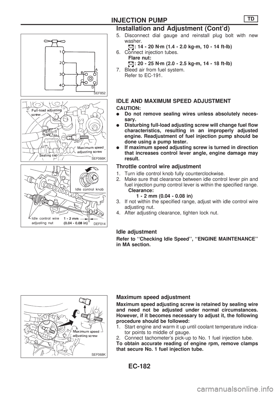
5. Disconnect dial gauge and reinstall plug bolt with new
washer.
:14-20Nzm (1.4 - 2.0 kg-m, 10 - 14 ft-lb)
6. Connect injection tubes.
Flare nut:
:20-25Nzm (2.0 - 2.5 kg-m, 14 - 18 ft-lb)
7. Bleed air from fuel system.
Refer to EC-191.
IDLE AND MAXIMUM SPEED ADJUSTMENT
CAUTION:
lDo not remove sealing wires unless absolutely neces-
sary.
lDisturbing full-load adjusting screw will change fuel flow
characteristics, resulting in an improperly adjusted
engine. Readjustment of fuel injection pump should be
done using a pump tester.
lIf maximum speed adjusting screw is turned in direction
that increases control lever angle, engine damage may
result.
Throttle control wire adjustment
1. Turn idle control knob fully counterclockwise.
2. Make sure that clearance between idle control lever pin and
fuel injection pump control lever is within the specified range.
Clearance:
1-2mm(0.04 - 0.08 in)
3. If not within the specified range, adjust with idle control wire
adjusting nut.
4. After adjusting clearance, tighten lock nut.
Idle adjustment
Refer to ``Checking Idle Speed'', ``ENGINE MAINTENANCE''
in MA section.
Maximum speed adjustment
Maximum speed adjusting screw is retained by sealing wire
and need not be adjusted under normal circumstances.
However, if it becomes necessary to adjust it, the following
procedure should be followed:
1. Start engine and warm it up until coolant temperature indica-
tor points to middle of gauge.
2. Connect tachometer's pick-up to No. 1 fuel injection tube.
To obtain accurate reading of engine rpm, remove clamps
that secure No. 1 fuel injection tube.
SEF852
SEF066K
DEF014
SEF068K
INJECTION PUMPTD
Installation and Adjustment (Cont'd)
EC-182
Page 335 of 1659
3. Depress accelerator pedal fully under no load and, at this
point, read the tachometer indication.
Maximum engine speed (Under no load):
5,000
+100
-200rpm
4. If indication is lower than specified maximum engine speed,
turn maximum speed adjusting screw counterclockwise 1 or
2 rotations. Then depress accelerator pedal to floor under no
load and, at this point, read indication.
5. If indication is still lower than specified speed, repeat step 4
above until specified engine speed is reached.
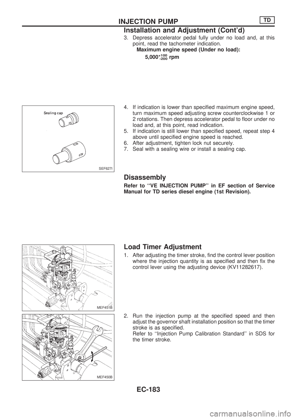
6. After adjustment, tighten lock nut securely.
7. Seal with a sealing wire or install a sealing cap.
Disassembly
Refer to ``VE INJECTION PUMP'' in EF section of Service
Manual for TD series diesel engine (1st Revision).
Load Timer Adjustment
1. After adjusting the timer stroke, find the control lever position
where the injection quantity is as specified and then fix the
control lever using the adjusting device (KV11282617).
2. Run the injection pump at the specified speed and then
adjust the governor shaft installation position so that the timer
stroke is as specified.
Refer to ``Injection Pump Calibration Standard'' in SDS for
the timer stroke.
SEF627I
MEF451B
MEF450B
INJECTION PUMPTD
Installation and Adjustment (Cont'd)
EC-183
Page 336 of 1659
Start Q Adjustment Lever
DISASSEMBLY
1. Attach injection pump to bracket using two bolts.
2. Remove start Q adjustment lever by removing nut after mark-
ing the installation position.
3. Remove nut and washer from the tip of lever shaft and then
remove start Q adjustment lever, spring, washer and O-ring.
4. Remove lever shaft and washer from the inside of governor
cover.
INSPECTION
1. Check that lever shaft's sliding surface is not worn, scratched
or damaged excessively and that lever shaft's flange is not
bent, worn or damaged excessively.
Replace lever shaft it defective.
2. Inspect the other parts carefully. If they are damaged, worn,
rusted or bent excessively they must be replaced.
REASSEMBLY
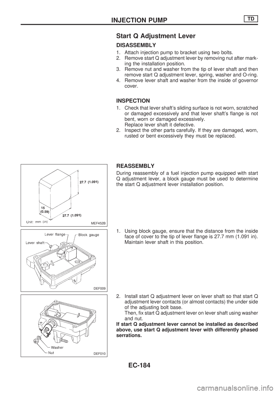
During reassembly of a fuel injection pump equipped with start
Q adjustment lever, a block gauge must be used to determine
the start Q adjustment lever installation position.
1. Using block gauge, ensure that the distance from the inside
face of cover to the tip of lever flange is 27.7 mm (1.091 in).
Maintain lever shaft in this position.
2. Install start Q adjustment lever on lever shaft so that start Q
adjustment lever contacts (or almost contacts) the under side
of the adjusting bolt base.
Then, fix start Q adjustment lever on lever shaft using washer
and nut.
If start Q adjustment lever cannot be installed as described
above, use start Q adjustment lever with differently phased
serrations.
MEF452B
DEF009
DEF010
INJECTION PUMPTD
EC-184
Page 337 of 1659
ADJUSTMENT
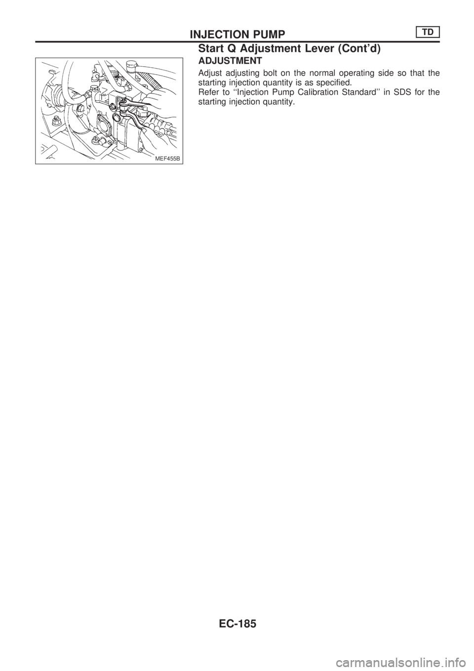
Adjust adjusting bolt on the normal operating side so that the
starting injection quantity is as specified.
Refer to ``Injection Pump Calibration Standard'' in SDS for the
starting injection quantity.
MEF455B
INJECTION PUMPTD
Start Q Adjustment Lever (Cont'd)
EC-185
Page 338 of 1659
Removal and Installation
1. Remove injection tube assembly.
2. Remove spill tube assembly.
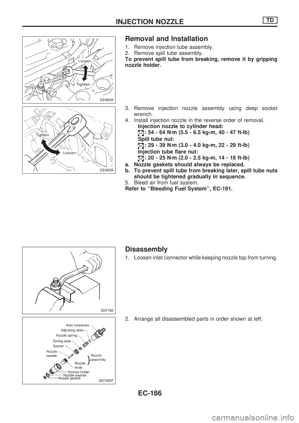
To prevent spill tube from breaking, remove it by gripping
nozzle holder.
3. Remove injection nozzle assembly using deep socket
wrench.
4. Install injection nozzle in the reverse order of removal.
Injection nozzle to cylinder head:
:54-64Nzm (5.5 - 6.5 kg-m, 40 - 47 ft-lb)
Spill tube nut:
:29-39Nzm (3.0 - 4.0 kg-m, 22 - 29 ft-lb)
Injection tube flare nut:
:20-25Nzm (2.0 - 2.5 kg-m, 14 - 18 ft-lb)
a. Nozzle gaskets should always be replaced.
b. To prevent spill tube from breaking later, spill tube nuts
should be tightened gradually in sequence.
5. Bleed air from fuel system.
Refer to ``Bleeding Fuel System'', EC-191.
Disassembly
1. Loosen inlet connector while keeping nozzle top from turning.
2. Arrange all disassembled parts in order shown at left.
DEM025
DEM026
SEF785
SEF425F
INJECTION NOZZLETD
EC-186
Page 339 of 1659
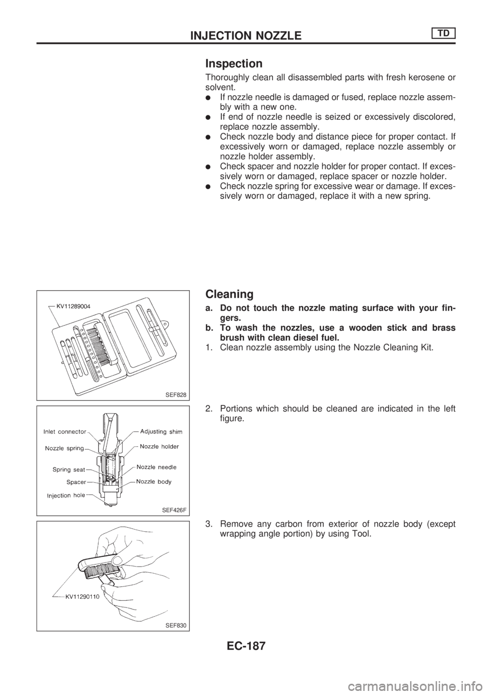
Inspection
Thoroughly clean all disassembled parts with fresh kerosene or
solvent.
lIf nozzle needle is damaged or fused, replace nozzle assem-
bly with a new one.
lIf end of nozzle needle is seized or excessively discolored,
replace nozzle assembly.
lCheck nozzle body and distance piece for proper contact. If
excessively worn or damaged, replace nozzle assembly or
nozzle holder assembly.
lCheck spacer and nozzle holder for proper contact. If exces-
sively worn or damaged, replace spacer or nozzle holder.
lCheck nozzle spring for excessive wear or damage. If exces-
sively worn or damaged, replace it with a new spring.
Cleaning
a. Do not touch the nozzle mating surface with your fin-
gers.
b. To wash the nozzles, use a wooden stick and brass
brush with clean diesel fuel.
1. Clean nozzle assembly using the Nozzle Cleaning Kit.
2. Portions which should be cleaned are indicated in the left
figure.
3. Remove any carbon from exterior of nozzle body (except
wrapping angle portion) by using Tool.
SEF828
SEF426F
SEF830
INJECTION NOZZLETD
EC-187
Page 340 of 1659
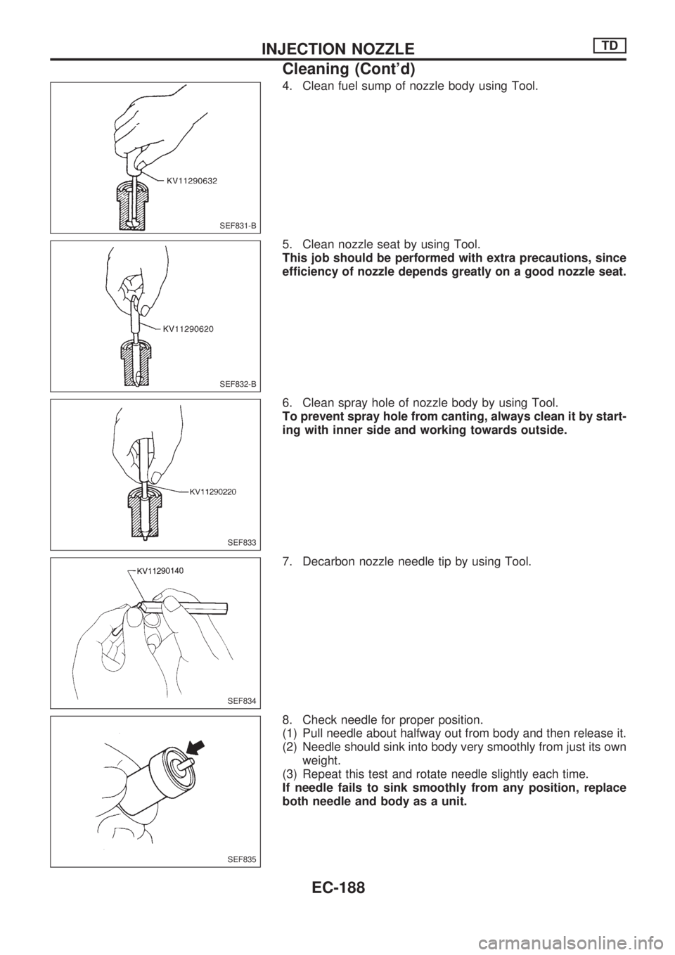
4. Clean fuel sump of nozzle body using Tool.
5. Clean nozzle seat by using Tool.
This job should be performed with extra precautions, since
efficiency of nozzle depends greatly on a good nozzle seat.
6. Clean spray hole of nozzle body by using Tool.
To prevent spray hole from canting, always clean it by start-
ing with inner side and working towards outside.
7. Decarbon nozzle needle tip by using Tool.
8. Check needle for proper position.
(1) Pull needle about halfway out from body and then release it.
(2) Needle should sink into body very smoothly from just its own
weight.
(3) Repeat this test and rotate needle slightly each time.
If needle fails to sink smoothly from any position, replace
both needle and body as a unit.
SEF831-B
SEF832-B
SEF833
SEF834
SEF835
INJECTION NOZZLETD
Cleaning (Cont'd)
EC-188