NISSAN PICK-UP 1998 Repair Manual
Manufacturer: NISSAN, Model Year: 1998, Model line: PICK-UP, Model: NISSAN PICK-UP 1998Pages: 1659, PDF Size: 53.39 MB
Page 411 of 1659
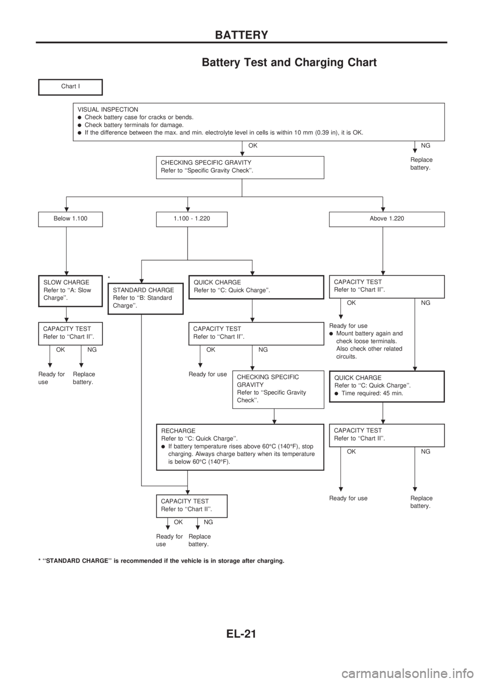
Battery Test and Charging Chart
Chart I
VISUAL INSPECTIONlCheck battery case for cracks or bends.lCheck battery terminals for damage.lIf the difference between the max. and min. electrolyte level in cells is within 10 mm (0.39 in), it is OK.
OK NG
CHECKING SPECIFIC GRAVITY
Refer to ``Specific Gravity Check''.
Replace
battery.
Below 1.1001.100 - 1.220Above 1.220
SLOW CHARGE
Refer to ``A: Slow
Charge''.*
STANDARD CHARGE
Refer to ``B: Standard
Charge''.QUICK CHARGE
Refer to ``C: Quick Charge''.CAPACITY TEST
Refer to ``Chart II''.
OK NG
CAPACITY TEST
Refer to ``Chart II''.
OK NGCAPACITY TEST
Refer to ``Chart II''.OK NGReady for use
lMount battery again and
check loose terminals.
Also check other related
circuits.
Ready for
useReplace
battery.Ready for use
CHECKING SPECIFIC
GRAVITY
Refer to ``Specific Gravity
Check''.
QUICK CHARGE
Refer to ``C: Quick Charge''.
lTime required: 45 min.
RECHARGE
Refer to ``C: Quick Charge''.
lIf battery temperature rises above 60ÉC (140ÉF), stop
charging. Always charge battery when its temperature
is below 60ÉC (140ÉF).
CAPACITY TEST
Refer to ``Chart II''.
OK NG
CAPACITY TEST
Refer to ``Chart II''.
OK NGReady for use Replace
battery.
Ready for
useReplace
battery.
* ``STANDARD CHARGE'' is recommended if the vehicle is in storage after charging.
..
...
....
...
.....
..
...
..
BATTERY
EL-21
Page 412 of 1659
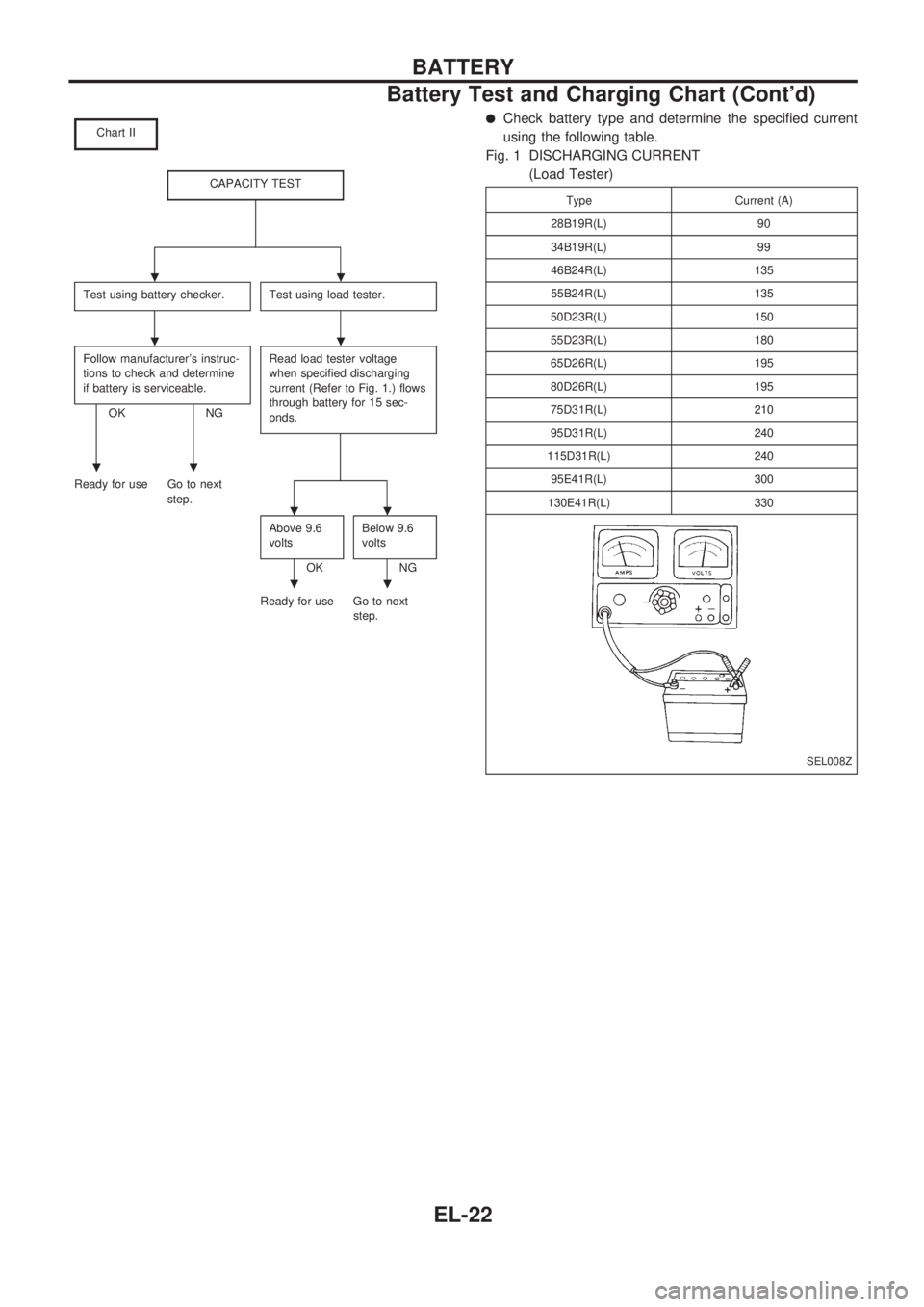
Chart II
CAPACITY TEST
Test using battery checker.Test using load tester.
Follow manufacturer's instruc-
tions to check and determine
if battery is serviceable.
OK NGRead load tester voltage
when specified discharging
current (Refer to Fig. 1.) flows
through battery for 15 sec-
onds.
Ready for use Go to next
step.
Above 9.6
volts
OKBelow 9.6
voltsNG
Ready for use Go to next
step.
lCheck battery type and determine the specified current
using the following table.
Fig. 1 DISCHARGING CURRENT
(Load Tester)
Type Current (A)
28B19R(L) 90
34B19R(L) 99
46B24R(L) 135
55B24R(L) 135
50D23R(L) 150
55D23R(L) 180
65D26R(L) 195
80D26R(L) 195
75D31R(L) 210
95D31R(L) 240
115D31R(L) 240
95E41R(L) 300
130E41R(L) 330
SEL008Z
..
..
..
..
..
BATTERY
Battery Test and Charging Chart (Cont'd)
EL-22
Page 413 of 1659
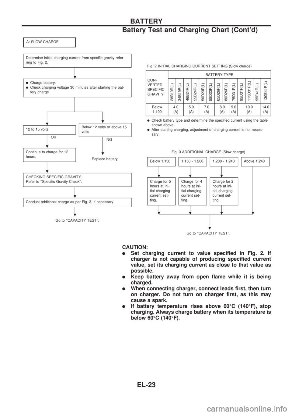
A: SLOW CHARGE
Determine initial charging current from specific gravity refer-
ring to Fig. 2.
lCharge battery.lCheck charging voltage 30 minutes after starting the bat-
tery charge.
12 to 15 volts
OKBelow 12 volts or above 15
voltsNG
Continue to charge for 12
hours.
Replace battery.
CHECKING SPECIFIC GRAVITY
Refer to ``Specific Gravity Check''.
Conduct additional charge as per Fig. 3, if necessary.
Go to ``CAPACITY TEST''.Fig. 2 INITIAL CHARGING CURRENT SETTING (Slow charge)
CON-
VERTED
SPECIFIC
GRAVITYBATTERY TYPE
28B19R(L)
34B19R(L)
46B24R(L)
55B24R(L)
50D23R(L)
55D23R(L)
65D26R(L)
80D26R(L)
75D31R(L)
95D31R(L)
115D31R(L)
95E41R(L)
130E41R(L)
Below
1.1004.0
(A)5.0
(A)7.0
(A)8.0
(A)9.0
(A)10.0
(A)14.0
(A)
lCheck battery type and determine the specified current using the table
shown above.
lAfter starting charging, adjustment of charging current is not neces-
sary.
Fig. 3 ADDITIONAL CHARGE (Slow charge)
Below 1.150
1.150 - 1.2001.200 - 1.240Above 1.240
Charge for 5
hours at ini-
tial charging
current set-
ting.Charge for 4
hours at ini-
tial charging
current set-
ting.Charge for 2
hours at ini-
tial charging
current set-
ting.
Go to ``CAPACITY TEST''.
.
CAUTION:
lSet charging current to value specified in Fig. 2. If
charger is not capable of producing specified current
value, set its charging current as close to that value as
possible.
lKeep battery away from open flame while it is being
charged.
lWhen connecting charger, connect leads first, then turn
on charger. Do not turn on charger first, as this may
cause a spark.
lIf battery temperature rises above 60ÉC (140ÉF), stop
charging. Always charge battery when its temperature is
below 60ÉC (140ÉF).
.
..
.
.
.
.
.
...
....
BATTERY
Battery Test and Charging Chart (Cont'd)
EL-23
Page 414 of 1659
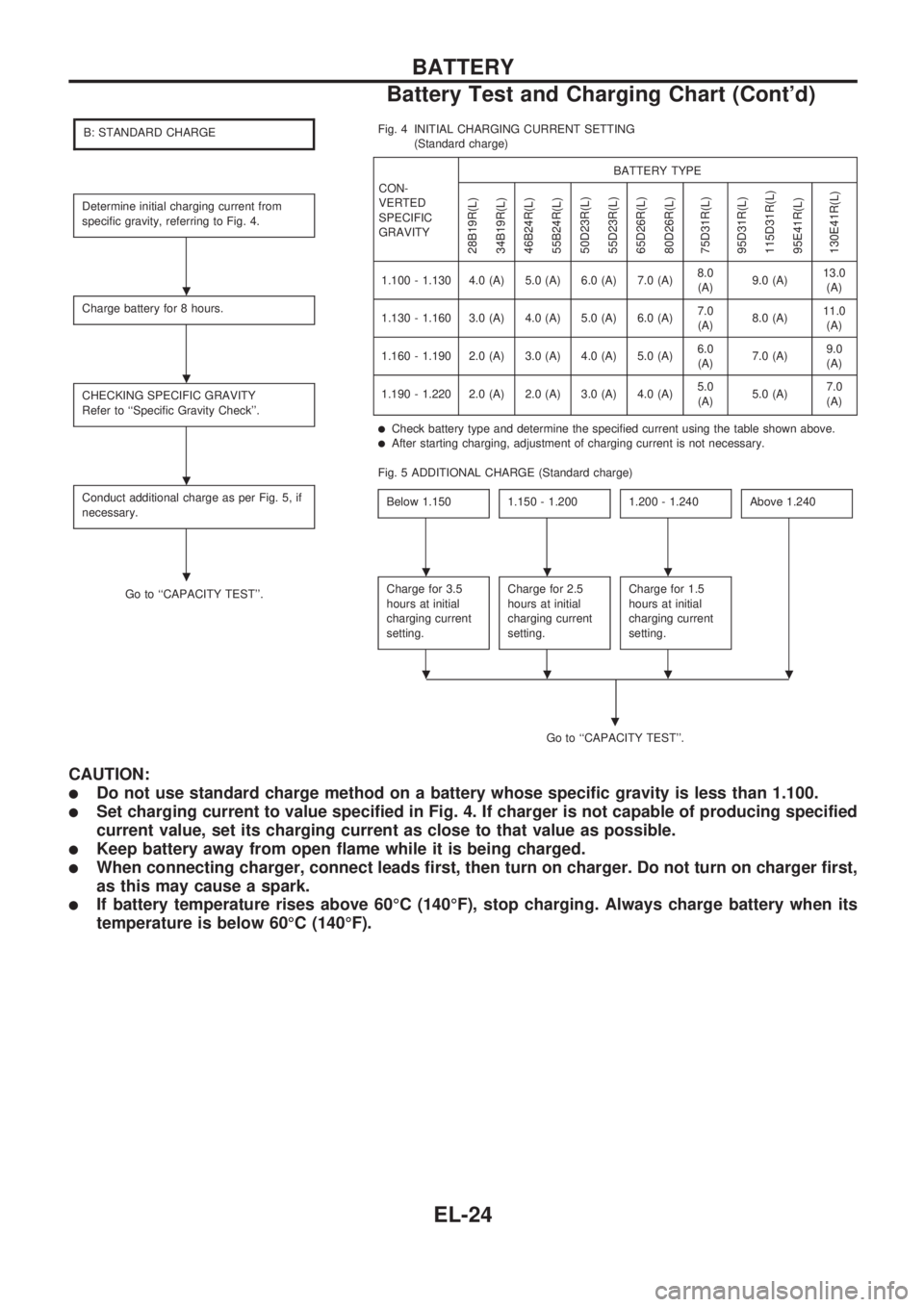
B: STANDARD CHARGE
Determine initial charging current from
specific gravity, referring to Fig. 4.
Charge battery for 8 hours.
CHECKING SPECIFIC GRAVITY
Refer to ``Specific Gravity Check''.
Conduct additional charge as per Fig. 5, if
necessary.
Go to ``CAPACITY TEST''.Fig. 4 INITIAL CHARGING CURRENT SETTING
(Standard charge)
CON-
VERTED
SPECIFIC
GRAVITYBATTERY TYPE
28B19R(L)
34B19R(L)
46B24R(L)
55B24R(L)
50D23R(L)
55D23R(L)
65D26R(L)
80D26R(L)
75D31R(L)
95D31R(L)
115D31R(L)
95E41R(L)
130E41R(L)
1.100 - 1.130 4.0 (A) 5.0 (A) 6.0 (A) 7.0 (A)8.0
(A)9.0 (A)13.0
(A)
1.130 - 1.160 3.0 (A) 4.0 (A) 5.0 (A) 6.0 (A)7.0
(A)8.0 (A)11.0
(A)
1.160 - 1.190 2.0 (A) 3.0 (A) 4.0 (A) 5.0 (A)6.0
(A)7.0 (A)9.0
(A)
1.190 - 1.220 2.0 (A) 2.0 (A) 3.0 (A) 4.0 (A)5.0
(A)5.0 (A)7.0
(A)
lCheck battery type and determine the specified current using the table shown above.lAfter starting charging, adjustment of charging current is not necessary.
Fig. 5 ADDITIONAL CHARGE (Standard charge)
Below 1.150
1.150 - 1.2001.200 - 1.240Above 1.240
Charge for 3.5
hours at initial
charging current
setting.Charge for 2.5
hours at initial
charging current
setting.Charge for 1.5
hours at initial
charging current
setting.
Go to ``CAPACITY TEST''.
.
CAUTION:
lDo not use standard charge method on a battery whose specific gravity is less than 1.100.
lSet charging current to value specified in Fig. 4. If charger is not capable of producing specified
current value, set its charging current as close to that value as possible.
lKeep battery away from open flame while it is being charged.
lWhen connecting charger, connect leads first, then turn on charger. Do not turn on charger first,
as this may cause a spark.
lIf battery temperature rises above 60ÉC (140ÉF), stop charging. Always charge battery when its
temperature is below 60ÉC (140ÉF).
.
.
.
....
....
BATTERY
Battery Test and Charging Chart (Cont'd)
EL-24
Page 415 of 1659
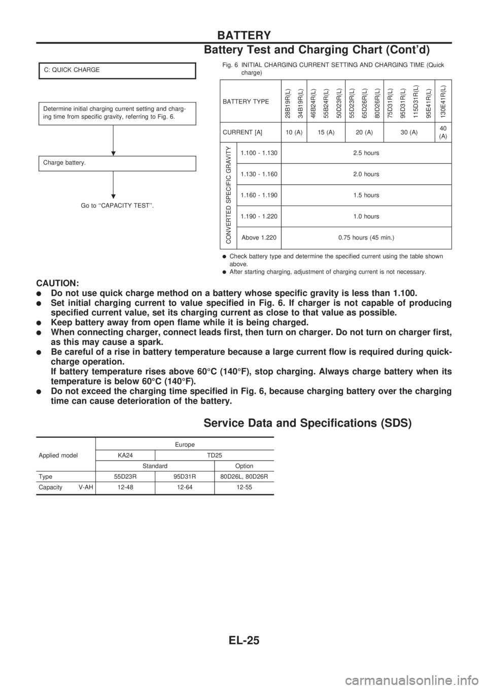
C: QUICK CHARGE
Determine initial charging current setting and charg-
ing time from specific gravity, referring to Fig. 6.
Charge battery.
Go to ``CAPACITY TEST''.Fig. 6 INITIAL CHARGING CURRENT SETTING AND CHARGING TIME (Quick
charge)
BATTERY TYPE
28B19R(L)
34B19R(L)
46B24R(L)
55B24R(L)
50D23R(L)
55D23R(L)
65D26R(L)
80D26R(L)
75D31R(L)
95D31R(L)
115D31R(L)
95E41R(L)
130E41R(L)
CURRENT [A] 10 (A) 15 (A) 20 (A) 30 (A)40
(A)
CONVERTED SPECIFIC GRAVITY
1.100 - 1.130 2.5 hours
1.130 - 1.160 2.0 hours
1.160 - 1.190 1.5 hours
1.190 - 1.220 1.0 hours
Above 1.220 0.75 hours (45 min.)
lCheck battery type and determine the specified current using the table shown
above.
lAfter starting charging, adjustment of charging current is not necessary.
CAUTION:
lDo not use quick charge method on a battery whose specific gravity is less than 1.100.
lSet initial charging current to value specified in Fig. 6. If charger is not capable of producing
specified current value, set its charging current as close to that value as possible.
lKeep battery away from open flame while it is being charged.
lWhen connecting charger, connect leads first, then turn on charger. Do not turn on charger first,
as this may cause a spark.
lBe careful of a rise in battery temperature because a large current flow is required during quick-
charge operation.
If battery temperature rises above 60ÉC (140ÉF), stop charging. Always charge battery when its
temperature is below 60ÉC (140ÉF).
lDo not exceed the charging time specified in Fig. 6, because charging battery over the charging
time can cause deterioration of the battery.
Service Data and Specifications (SDS)
Applied modelEurope
KA24 TD25
Standard Option
Type 55D23R 95D31R 80D26L, 80D26R
Capacity V-AH 12-48 12-64 12-55
.
.
BATTERY
Battery Test and Charging Chart (Cont'd)
EL-25
Page 416 of 1659
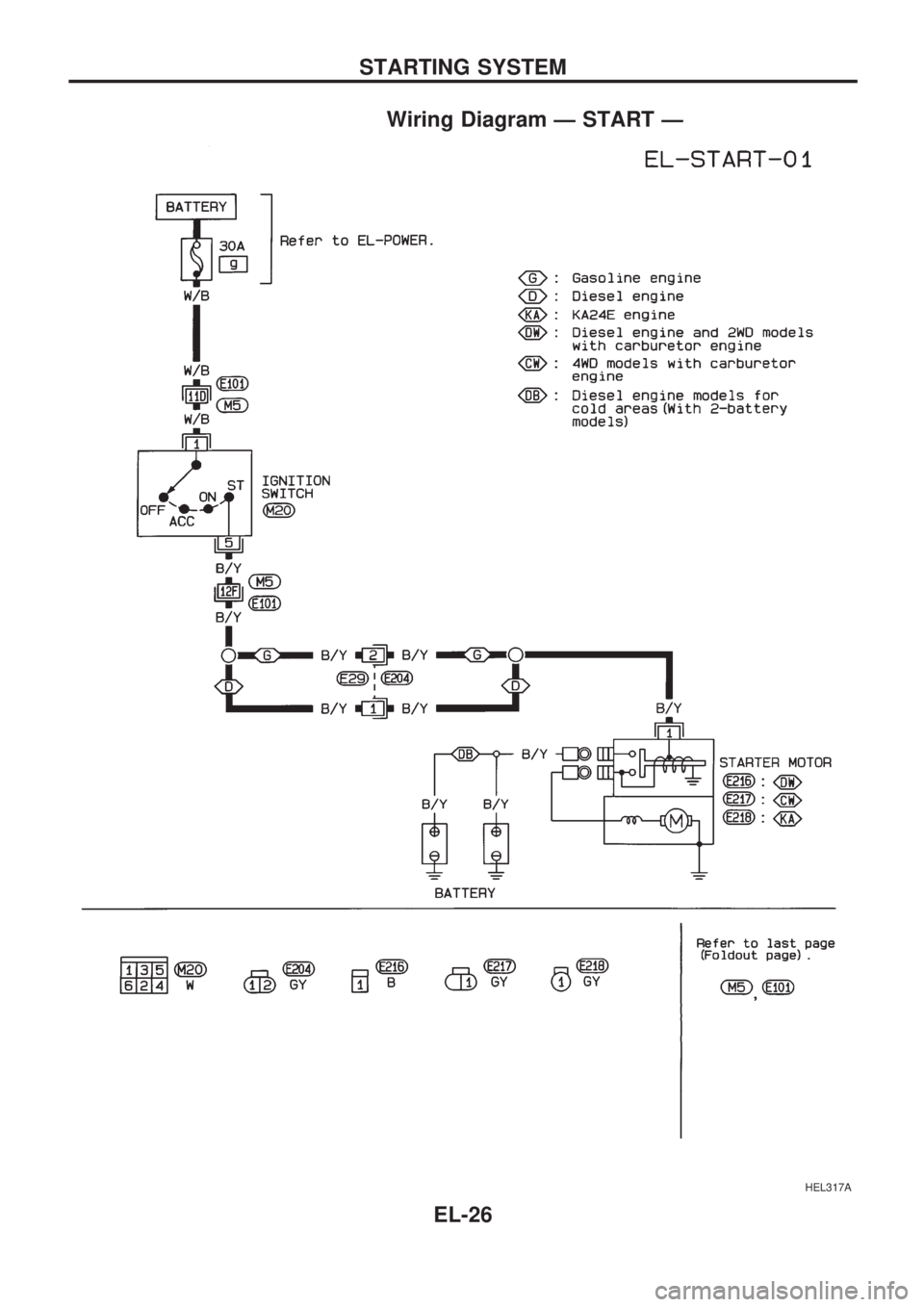
Wiring Diagram Ð START Ð
HEL317A
STARTING SYSTEM
EL-26
Page 417 of 1659
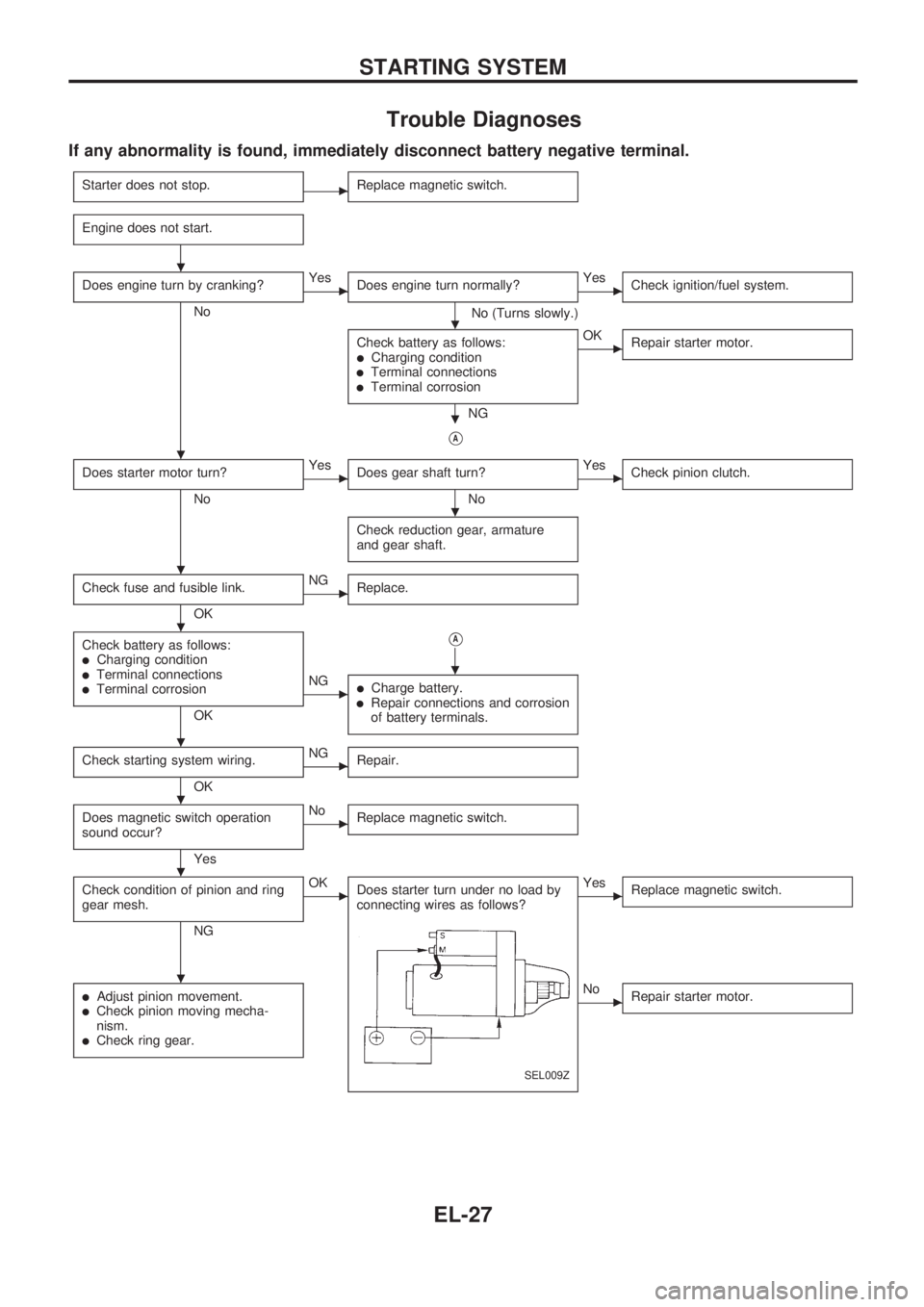
Trouble Diagnoses
If any abnormality is found, immediately disconnect battery negative terminal.
Starter does not stop.cReplace magnetic switch.
Engine does not start.
Does engine turn by cranking?
No
cYes
Does engine turn normally?
No (Turns slowly.)
cYes
Check ignition/fuel system.
Check battery as follows:lCharging conditionlTerminal connectionslTerminal corrosion
NG
cOK
Repair starter motor.
VA
Does starter motor turn?
No
cYes
Does gear shaft turn?
No
cYes
Check pinion clutch.
Check reduction gear, armature
and gear shaft.
Check fuse and fusible link.
OK
cNG
Replace.
Check battery as follows:lCharging conditionlTerminal connectionslTerminal corrosion
OK
VA
cNGlCharge battery.lRepair connections and corrosion
of battery terminals.
Check starting system wiring.
OK
cNG
Repair.
Does magnetic switch operation
sound occur?
Yes
cNo
Replace magnetic switch.
Check condition of pinion and ring
gear mesh.
NG
cOK
Does starter turn under no load by
connecting wires as follows?
SEL009Z
cYes
Replace magnetic switch.
lAdjust pinion movement.lCheck pinion moving mecha-
nism.
lCheck ring gear.
cNo
Repair starter motor.
.
.
.
.
.
.
.
.
.
.
.
.
STARTING SYSTEM
EL-27
Page 418 of 1659
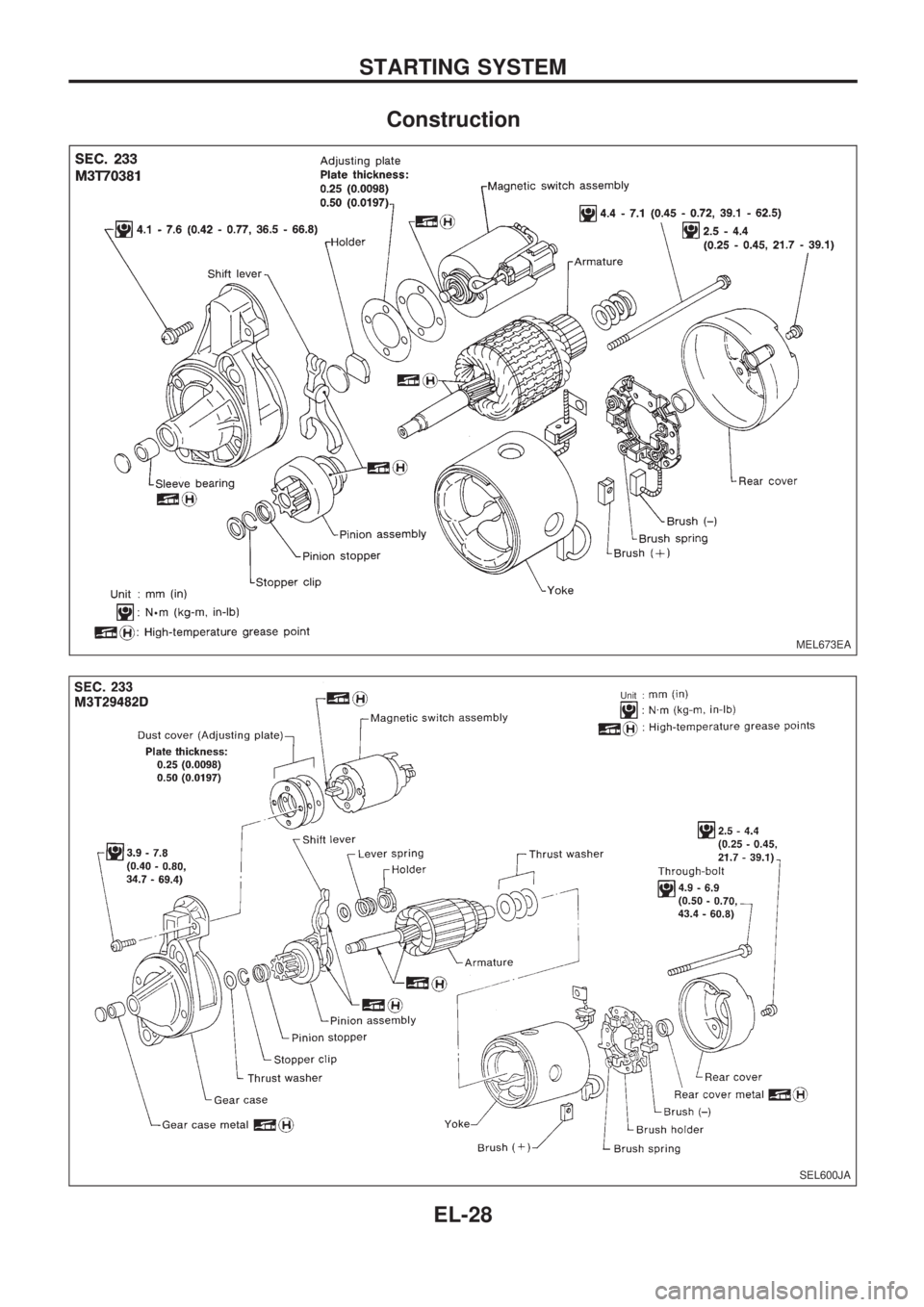
Construction
MEL673EA
SEL600JA
.Unit :
STARTING SYSTEM
EL-28
Page 419 of 1659
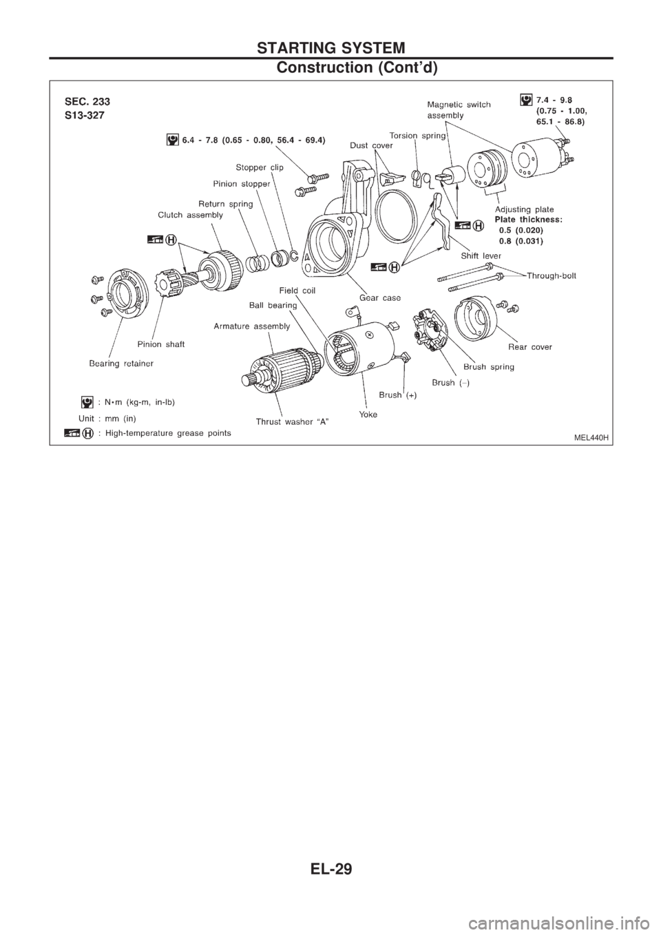
MEL440H
STARTING SYSTEM
Construction (Cont'd)
EL-29
Page 420 of 1659
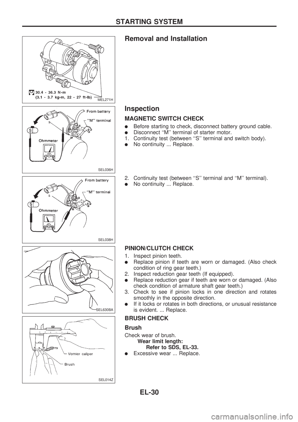
Removal and Installation
Inspection
MAGNETIC SWITCH CHECK
lBefore starting to check, disconnect battery ground cable.
lDisconnect ``M'' terminal of starter motor.
1. Continuity test (between ``S'' terminal and switch body).
lNo continuity ... Replace.
2. Continuity test (between ``S'' terminal and ``M'' terminal).
lNo continuity ... Replace.
PINION/CLUTCH CHECK
1. Inspect pinion teeth.
lReplace pinion if teeth are worn or damaged. (Also check
condition of ring gear teeth.)
2. Inspect reduction gear teeth (If equipped).
lReplace reduction gear if teeth are worn or damaged. (Also
check condition of armature shaft gear teeth.)
3. Check to see if pinion locks in one direction and rotates
smoothly in the opposite direction.
lIf it locks or rotates in both directions, or unusual resistance
is evident. ... Replace.
BRUSH CHECK
Brush
Check wear of brush.
Wear limit length:
Refer to SDS, EL-33.
lExcessive wear ... Replace.
MEL271H
SEL036H
SEL038H
SEL630BA
SEL014Z
STARTING SYSTEM
EL-30