NISSAN PICK-UP 1998 Repair Manual
PICK-UP 1998
NISSAN
NISSAN
https://www.carmanualsonline.info/img/5/57374/w960_57374-0.png
NISSAN PICK-UP 1998 Repair Manual
Trending: spare tire, temperature sensor, octane, clutch, spark plugs, check engine, jump cable
Page 351 of 1659
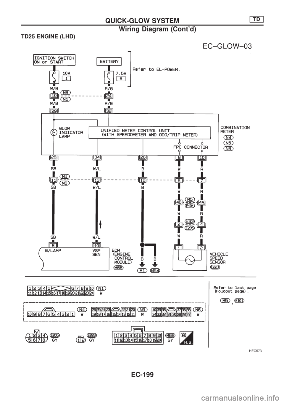
TD25 ENGINE (LHD)
HEC573
.
EC±GLOW±03
QUICK-GLOW SYSTEMTD
Wiring Diagram (Cont'd)
EC-199
Page 352 of 1659
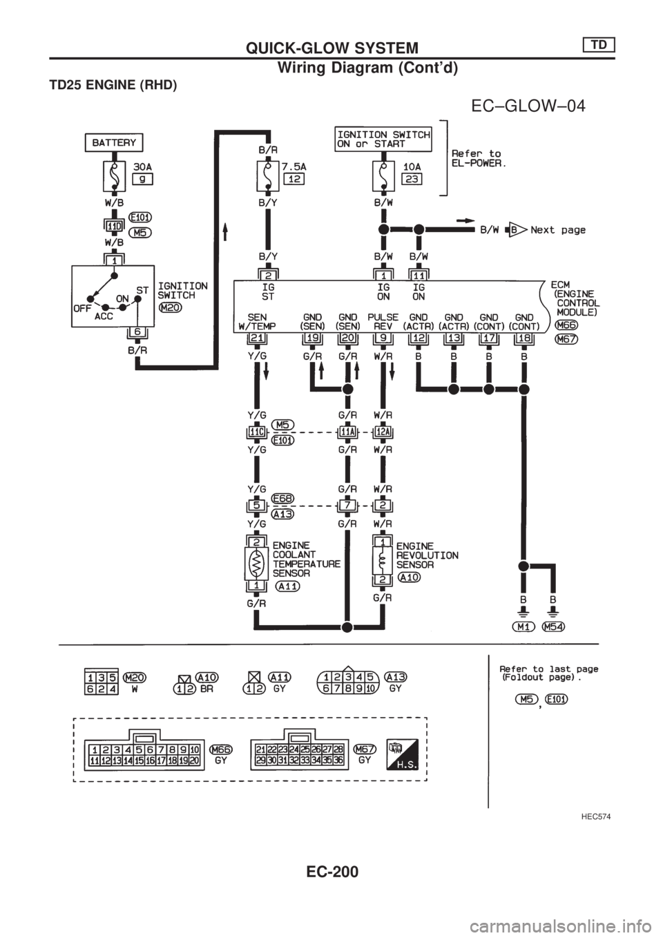
TD25 ENGINE (RHD)
HEC574
.
EC±GLOW±04
QUICK-GLOW SYSTEMTD
Wiring Diagram (Cont'd)
EC-200
Page 353 of 1659
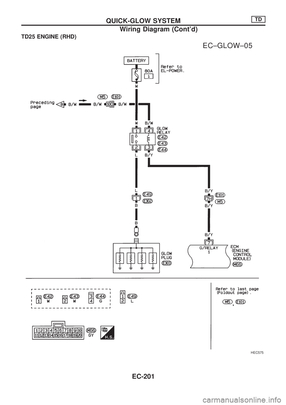
TD25 ENGINE (RHD)
HEC575
.
EC±GLOW±05
QUICK-GLOW SYSTEMTD
Wiring Diagram (Cont'd)
EC-201
Page 354 of 1659
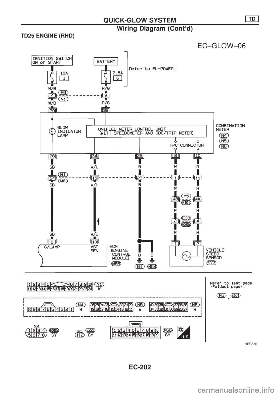
TD25 ENGINE (RHD)
HEC576
.
EC±GLOW±06
QUICK-GLOW SYSTEMTD
Wiring Diagram (Cont'd)
EC-202
Page 355 of 1659
Glow Control Unit Circuit Inspection (For
Cold Areas)
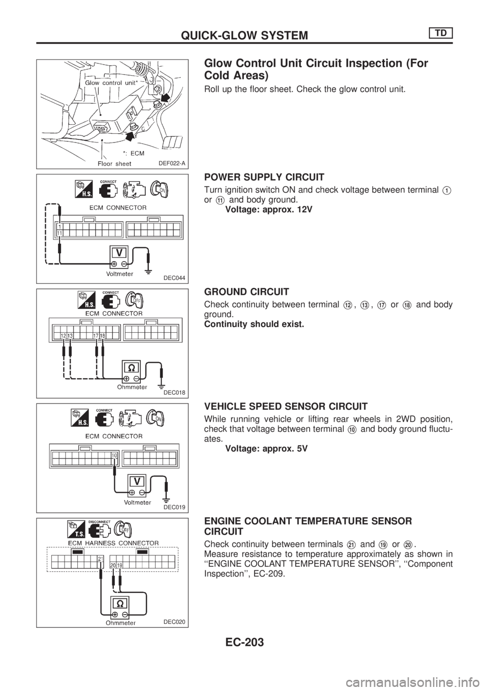
Roll up the floor sheet. Check the glow control unit.
POWER SUPPLY CIRCUIT
Turn ignition switch ON and check voltage between terminalV1
orV11and body ground.
Voltage: approx. 12V
GROUND CIRCUIT
Check continuity between terminalV12,V13,V17orV18and body
ground.
Continuity should exist.
VEHICLE SPEED SENSOR CIRCUIT
While running vehicle or lifting rear wheels in 2WD position,
check that voltage between terminal
V10and body ground fluctu-
ates.
Voltage: approx. 5V
ENGINE COOLANT TEMPERATURE SENSOR
CIRCUIT
Check continuity between terminalsV21andV19orV20.
Measure resistance to temperature approximately as shown in
``ENGINE COOLANT TEMPERATURE SENSOR'', ``Component
Inspection'', EC-209.
DEF022-A
.
DEC044
DEC018
DEC019
DEC020
QUICK-GLOW SYSTEMTD
EC-203
Page 356 of 1659
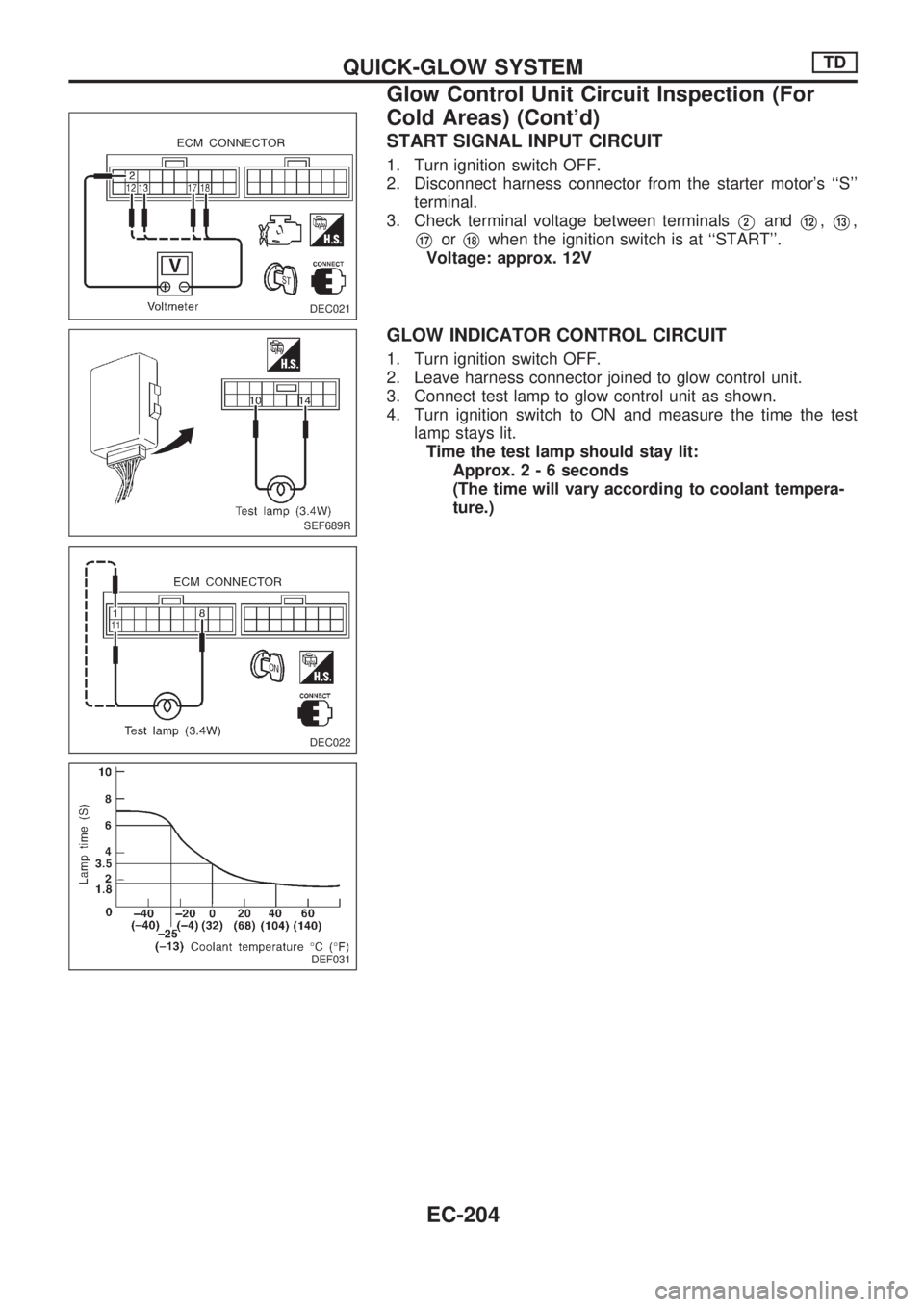
START SIGNAL INPUT CIRCUIT
1. Turn ignition switch OFF.
2. Disconnect harness connector from the starter motor's ``S''
terminal.
3. Check terminal voltage between terminals
V2andV12,V13,
V17orV18when the ignition switch is at ``START''.
Voltage: approx. 12V
GLOW INDICATOR CONTROL CIRCUIT
1. Turn ignition switch OFF.
2. Leave harness connector joined to glow control unit.
3. Connect test lamp to glow control unit as shown.
4. Turn ignition switch to ON and measure the time the test
lamp stays lit.
Time the test lamp should stay lit:
Approx.2-6seconds
(The time will vary according to coolant tempera-
ture.)
DEC021
SEF689R
DEC022
DEF031
QUICK-GLOW SYSTEMTD
Glow Control Unit Circuit Inspection (For
Cold Areas) (Cont'd)
EC-204
Page 357 of 1659
PRE-GLOW CONTROL CIRCUIT
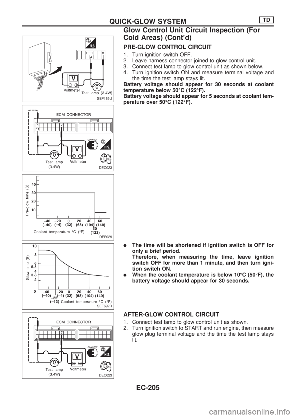
1. Turn ignition switch OFF.
2. Leave harness connector joined to glow control unit.
3. Connect test lamp to glow control unit as shown below.
4. Turn ignition switch ON and measure terminal voltage and
the time the test lamp stays lit.
Battery voltage should appear for 30 seconds at coolant
temperature below 50ÉC (122ÉF).
Battery voltage should appear for 5 seconds at coolant tem-
perature over 50ÉC (122ÉF).
lThe time will be shortened if ignition switch is OFF for
only a brief period.
Therefore, when measuring the time, leave ignition
switch OFF for more than 1 minute, and then turn igni-
tion switch ON.
lWhen the coolant temperature is below 10ÉC (50ÉF), the
battery voltage should appear for 30 seconds.
AFTER-GLOW CONTROL CIRCUIT
1. Connect test lamp to glow control unit as shown.
2. Turn ignition switch to START and run engine, then measure
glow plug terminal voltage and the time the test lamp stays
lit.
SEF169U
DEC023
DEF029
SEF692R
DEC023
QUICK-GLOW SYSTEMTD
Glow Control Unit Circuit Inspection (For
Cold Areas) (Cont'd)
EC-205
Page 358 of 1659
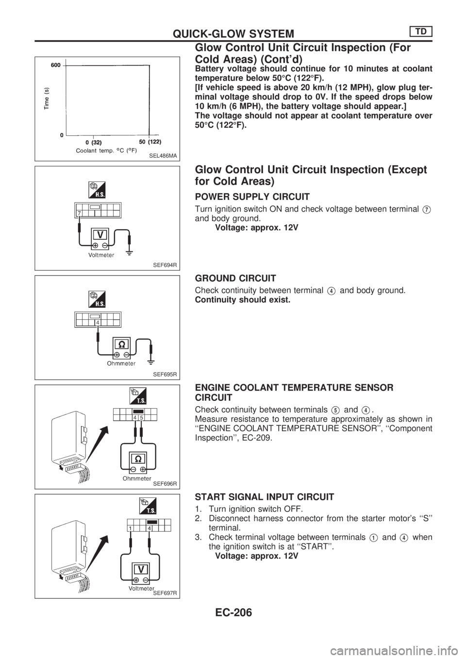
Battery voltage should continue for 10 minutes at coolant
temperature below 50ÉC (122ÉF).
[If vehicle speed is above 20 km/h (12 MPH), glow plug ter-
minal voltage should drop to 0V. If the speed drops below
10 km/h (6 MPH), the battery voltage should appear.]
The voltage should not appear at coolant temperature over
50ÉC (122ÉF).
Glow Control Unit Circuit Inspection (Except
for Cold Areas)
POWER SUPPLY CIRCUIT
Turn ignition switch ON and check voltage between terminalV7
and body ground.
Voltage: approx. 12V
GROUND CIRCUIT
Check continuity between terminalV4and body ground.
Continuity should exist.
ENGINE COOLANT TEMPERATURE SENSOR
CIRCUIT
Check continuity between terminalsV5andV4.
Measure resistance to temperature approximately as shown in
``ENGINE COOLANT TEMPERATURE SENSOR'', ``Component
Inspection'', EC-209.
START SIGNAL INPUT CIRCUIT
1. Turn ignition switch OFF.
2. Disconnect harness connector from the starter motor's ``S''
terminal.
3. Check terminal voltage between terminals
V1andV4when
the ignition switch is at ``START''.
Voltage: approx. 12V
SEL486MA
SEF694R
SEF695R
SEF696R
SEF697R
QUICK-GLOW SYSTEMTD
Glow Control Unit Circuit Inspection (For
Cold Areas) (Cont'd)
EC-206
Page 359 of 1659
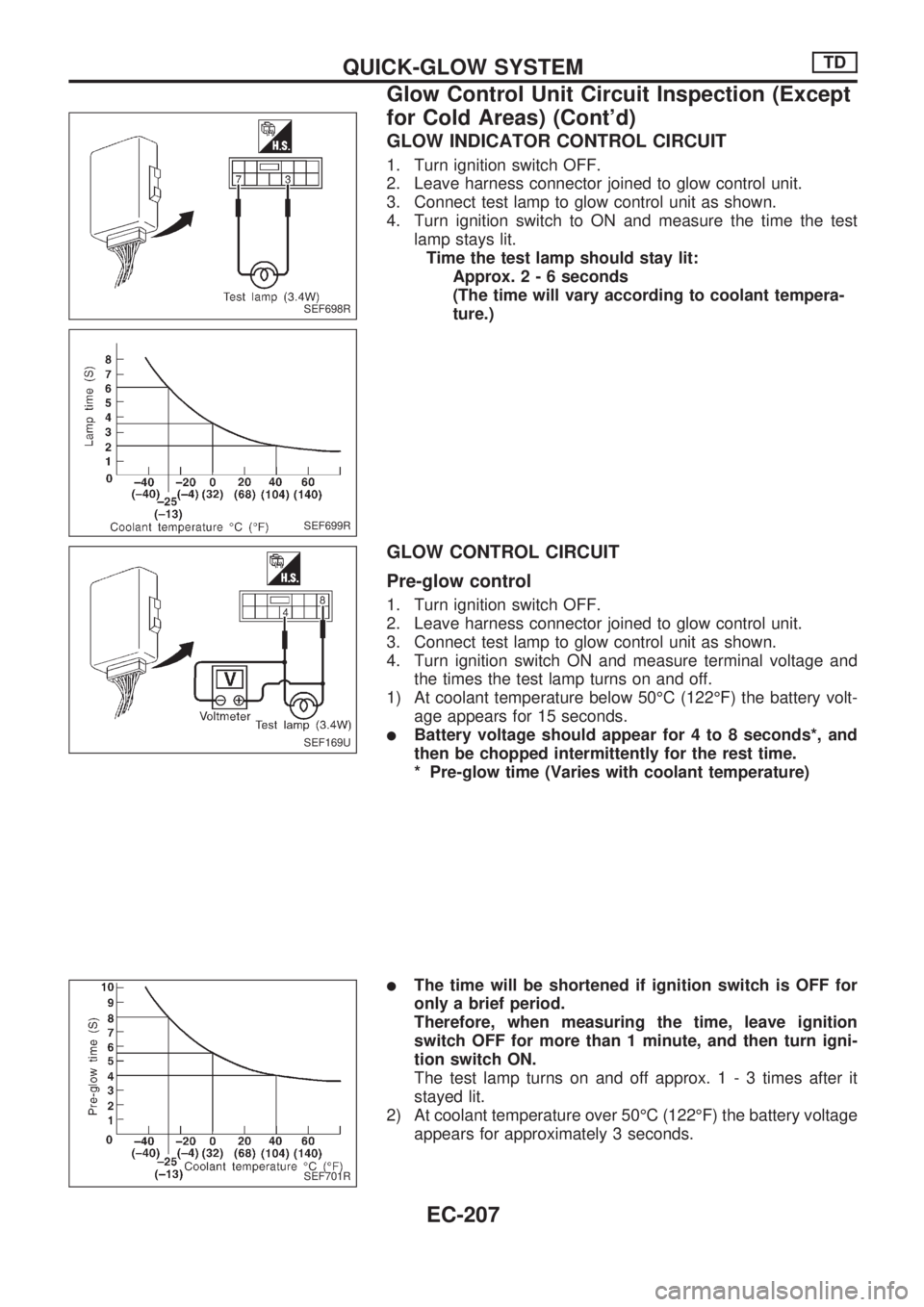
GLOW INDICATOR CONTROL CIRCUIT
1. Turn ignition switch OFF.
2. Leave harness connector joined to glow control unit.
3. Connect test lamp to glow control unit as shown.
4. Turn ignition switch to ON and measure the time the test
lamp stays lit.
Time the test lamp should stay lit:
Approx.2-6seconds
(The time will vary according to coolant tempera-
ture.)
GLOW CONTROL CIRCUIT
Pre-glow control
1. Turn ignition switch OFF.
2. Leave harness connector joined to glow control unit.
3. Connect test lamp to glow control unit as shown.
4. Turn ignition switch ON and measure terminal voltage and
the times the test lamp turns on and off.
1) At coolant temperature below 50ÉC (122ÉF) the battery volt-
age appears for 15 seconds.
lBattery voltage should appear for 4 to 8 seconds*, and
then be chopped intermittently for the rest time.
* Pre-glow time (Varies with coolant temperature)
lThe time will be shortened if ignition switch is OFF for
only a brief period.
Therefore, when measuring the time, leave ignition
switch OFF for more than 1 minute, and then turn igni-
tion switch ON.
The test lamp turns on and off approx. 1 - 3 times after it
stayed lit.
2) At coolant temperature over 50ÉC (122ÉF) the battery voltage
appears for approximately 3 seconds.
SEF698R
SEF699R
SEF169U
SEF701R
QUICK-GLOW SYSTEMTD
Glow Control Unit Circuit Inspection (Except
for Cold Areas) (Cont'd)
EC-207
Page 360 of 1659
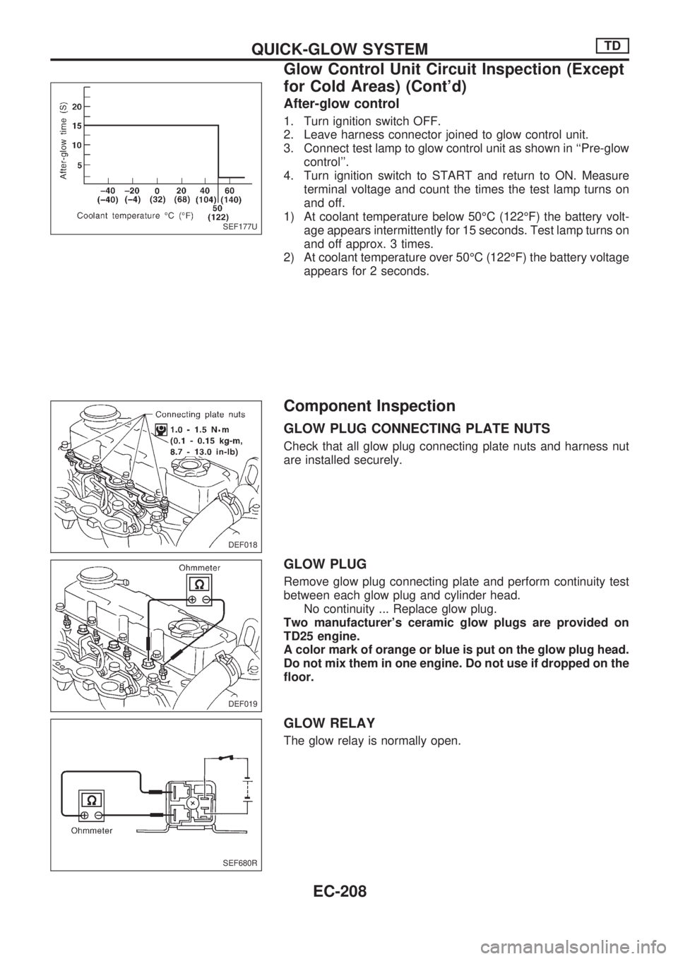
After-glow control
1. Turn ignition switch OFF.
2. Leave harness connector joined to glow control unit.
3. Connect test lamp to glow control unit as shown in ``Pre-glow
control''.
4. Turn ignition switch to START and return to ON. Measure
terminal voltage and count the times the test lamp turns on
and off.
1) At coolant temperature below 50ÉC (122ÉF) the battery volt-
age appears intermittently for 15 seconds. Test lamp turns on
and off approx. 3 times.
2) At coolant temperature over 50ÉC (122ÉF) the battery voltage
appears for 2 seconds.
Component Inspection
GLOW PLUG CONNECTING PLATE NUTS
Check that all glow plug connecting plate nuts and harness nut
are installed securely.
GLOW PLUG
Remove glow plug connecting plate and perform continuity test
between each glow plug and cylinder head.
No continuity ... Replace glow plug.
Two manufacturer's ceramic glow plugs are provided on
TD25 engine.
A color mark of orange or blue is put on the glow plug head.
Do not mix them in one engine. Do not use if dropped on the
floor.
GLOW RELAY
The glow relay is normally open.
SEF177U
DEF018
DEF019
SEF680R
QUICK-GLOW SYSTEMTD
Glow Control Unit Circuit Inspection (Except
for Cold Areas) (Cont'd)
EC-208
Trending: ABS, fuel cap release, service, fuses, oil level, radio, heater
