NISSAN PICK-UP 1998 Repair Manual
Manufacturer: NISSAN, Model Year: 1998, Model line: PICK-UP, Model: NISSAN PICK-UP 1998Pages: 1659, PDF Size: 53.39 MB
Page 381 of 1659
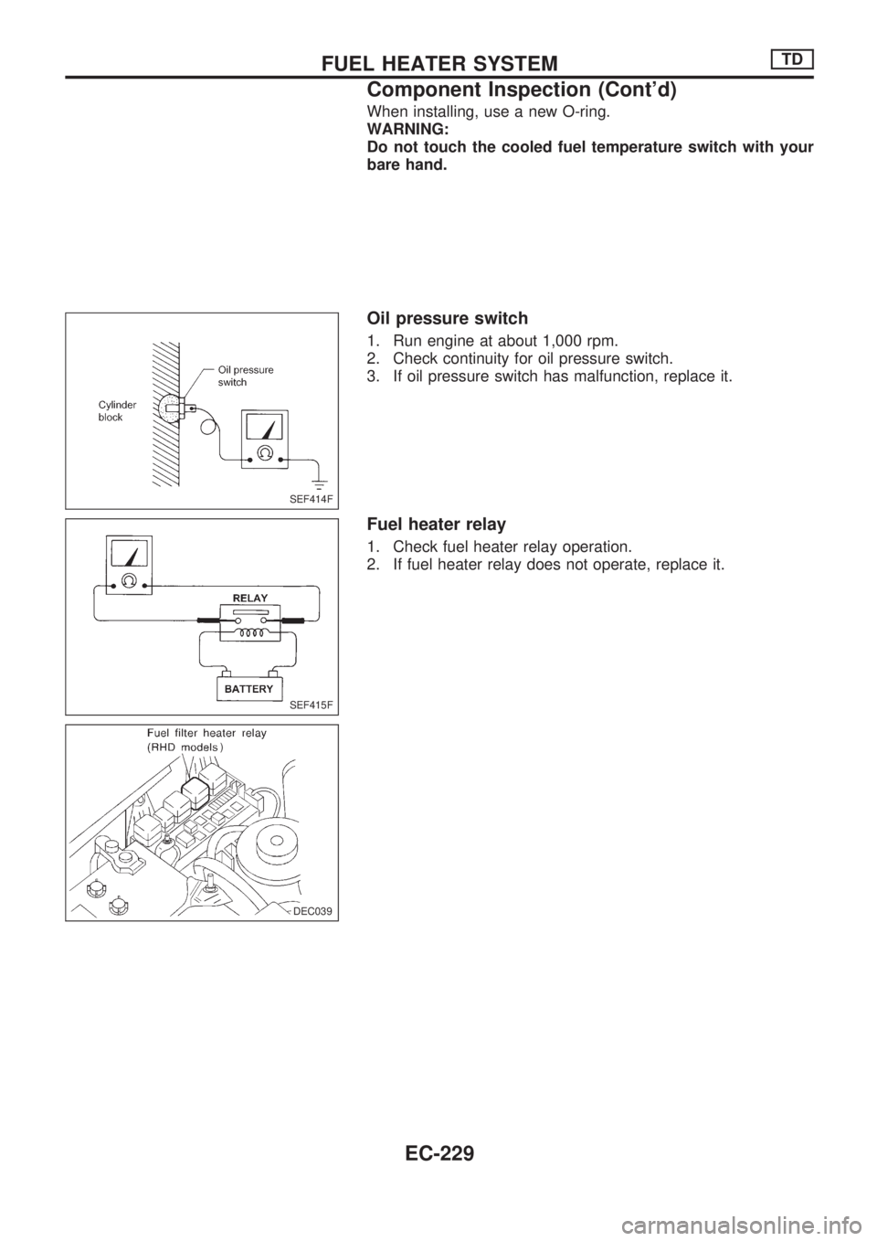
When installing, use a new O-ring.
WARNING:
Do not touch the cooled fuel temperature switch with your
bare hand.
Oil pressure switch
1. Run engine at about 1,000 rpm.
2. Check continuity for oil pressure switch.
3. If oil pressure switch has malfunction, replace it.
Fuel heater relay
1. Check fuel heater relay operation.
2. If fuel heater relay does not operate, replace it.
SEF414F
SEF415F
DEC039
.)
.DEC039
FUEL HEATER SYSTEMTD
Component Inspection (Cont'd)
EC-229
Page 382 of 1659
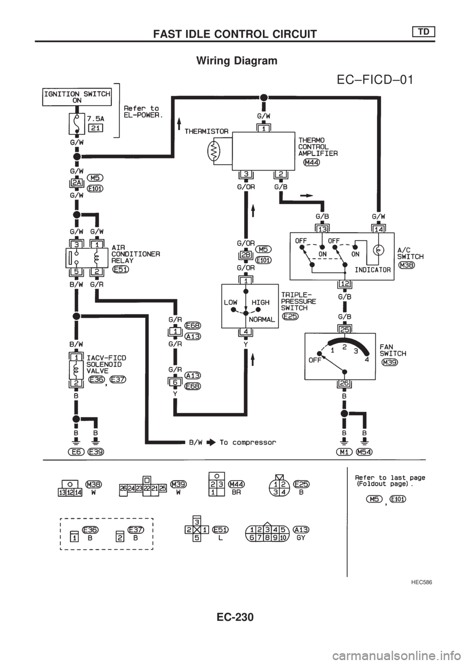
Wiring Diagram
HEC586
.
EC±FICD±01
FAST IDLE CONTROL CIRCUITTD
EC-230
Page 383 of 1659
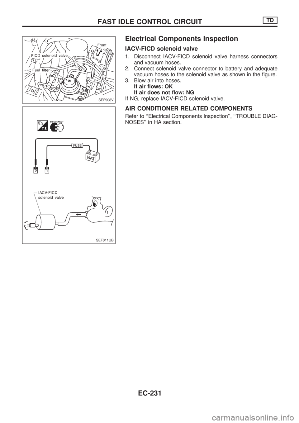
Electrical Components Inspection
IACV-FICD solenoid valve
1. Disconnect IACV-FICD solenoid valve harness connectors
and vacuum hoses.
2. Connect solenoid valve connector to battery and adequate
vacuum hoses to the solenoid valve as shown in the figure.
3. Blow air into hoses.
If air flows: OK
If air does not flow: NG
If NG, replace IACV-FICD solenoid valve.
AIR CONDITIONER RELATED COMPONENTS
Refer to ``Electrical Components Inspection'', ``TROUBLE DIAG-
NOSES'' in HA section.
SEF908V
SEF011UB
FAST IDLE CONTROL CIRCUITTD
EC-231
Page 384 of 1659
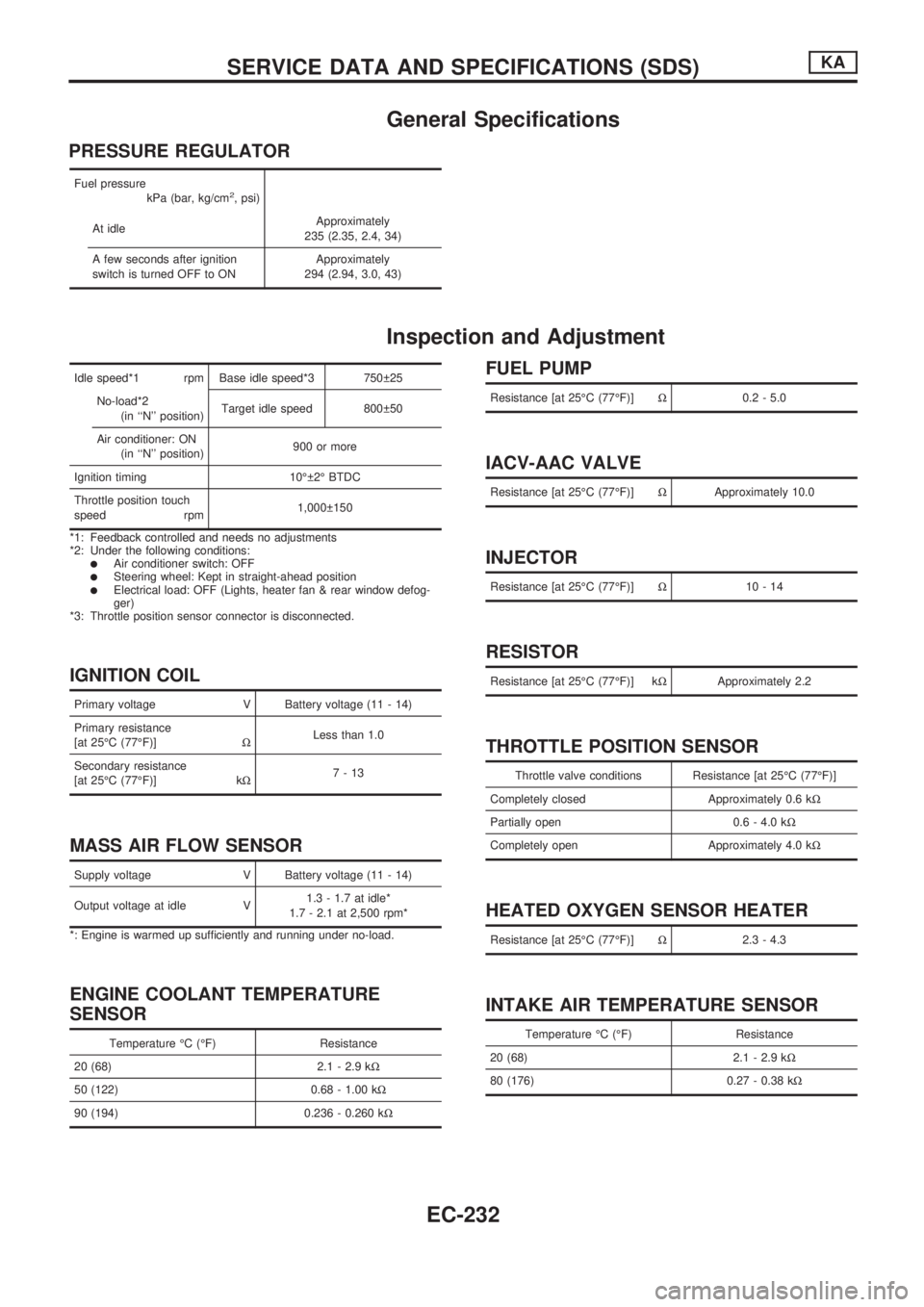
General Specifications
PRESSURE REGULATOR
Fuel pressure
kPa (bar, kg/cm2, psi)
At idleApproximately
235 (2.35, 2.4, 34)
A few seconds after ignition
switch is turned OFF to ONApproximately
294 (2.94, 3.0, 43)
Inspection and Adjustment
Idle speed*1 rpm Base idle speed*3 750 25
No-load*2
(in ``N'' position)Target idle speed 800 50
Air conditioner: ON
(in ``N'' position)900 or more
Ignition timing 10É 2É BTDC
Throttle position touch
speed rpm1,000 150
*1: Feedback controlled and needs no adjustments
*2: Under the following conditions:
lAir conditioner switch: OFFlSteering wheel: Kept in straight-ahead positionlElectrical load: OFF (Lights, heater fan & rear window defog-
ger)
*3: Throttle position sensor connector is disconnected.
IGNITION COIL
Primary voltage V Battery voltage (11 - 14)
Primary resistance
[at 25ÉC (77ÉF)]WLess than 1.0
Secondary resistance
[at 25ÉC (77ÉF)] kW7-13
MASS AIR FLOW SENSOR
Supply voltage V Battery voltage (11 - 14)
Output voltage at idle V1.3 - 1.7 at idle*
1.7 - 2.1 at 2,500 rpm*
*: Engine is warmed up sufficiently and running under no-load.
ENGINE COOLANT TEMPERATURE
SENSOR
Temperature ÉC (ÉF) Resistance
20 (68) 2.1 - 2.9 kW
50 (122) 0.68 - 1.00 kW
90 (194) 0.236 - 0.260 kW
FUEL PUMP
Resistance [at 25ÉC (77ÉF)]W0.2 - 5.0
IACV-AAC VALVE
Resistance [at 25ÉC (77ÉF)]WApproximately 10.0
INJECTOR
Resistance [at 25ÉC (77ÉF)]W10-14
RESISTOR
Resistance [at 25ÉC (77ÉF)] kWApproximately 2.2
THROTTLE POSITION SENSOR
Throttle valve conditions Resistance [at 25ÉC (77ÉF)]
Completely closed Approximately 0.6 kW
Partially open 0.6 - 4.0 kW
Completely open Approximately 4.0 kW
HEATED OXYGEN SENSOR HEATER
Resistance [at 25ÉC (77ÉF)]W2.3 - 4.3
INTAKE AIR TEMPERATURE SENSOR
Temperature ÉC (ÉF) Resistance
20 (68) 2.1 - 2.9 kW
80 (176) 0.27 - 0.38 kW
SERVICE DATA AND SPECIFICATIONS (SDS)KA
EC-232
Page 385 of 1659
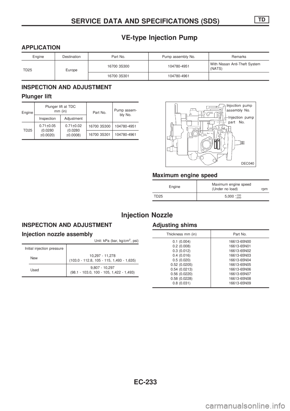
VE-type Injection Pump
APPLICATION
Engine Destination Part No. Pump assembly No. Remarks
TD25 Europe16700 3S300 104780-4951With Nissan Anti-Theft System
(NATS)
16700 3S301 104780-4961
INSPECTION AND ADJUSTMENT
Plunger lift
EnginePlunger lift at TDC
mm (in)
Part No.Pump assem-
bly No.
Inspection Adjustment
TD250.71 0.05
(0.0280
0.0020)0.71 0.02
(0.0280
0.0008)16700 3S300 104780-4951
16700 3S301 104780-4961
Maximum engine speed
EngineMaximum engine speed
(Under no load) rpm
TD25 5,000
+100
þ200
Injection Nozzle
INSPECTION AND ADJUSTMENT
Injection nozzle assembly
Unit: kPa (bar, kg/cm2, psi)
Initial injection pressure
New10,297 - 11,278
(103.0 - 112.8, 105 - 115, 1,493 - 1,635)
Used9,807 - 10,297
(98.1 - 103.0, 100 - 105, 1,422 - 1,493)
Adjusting shims
Thickness mm (in) Part No.
0.1 (0.004)
0.2 (0.008)
0.3 (0.012)
0.4 (0.016)
0.5 (0.020)
0.52 (0.0205)
0.54 (0.0213)
0.56 (0.0220)
0.58 (0.0228)
0.8 (0.031)16613-65N00
16613-65N01
16613-65N02
16613-65N03
16613-65N04
16613-65N05
16613-65N06
16613-65N07
16613-65N08
16613-65N09
DEC040
SERVICE DATA AND SPECIFICATIONS (SDS)TD
EC-233
Page 386 of 1659
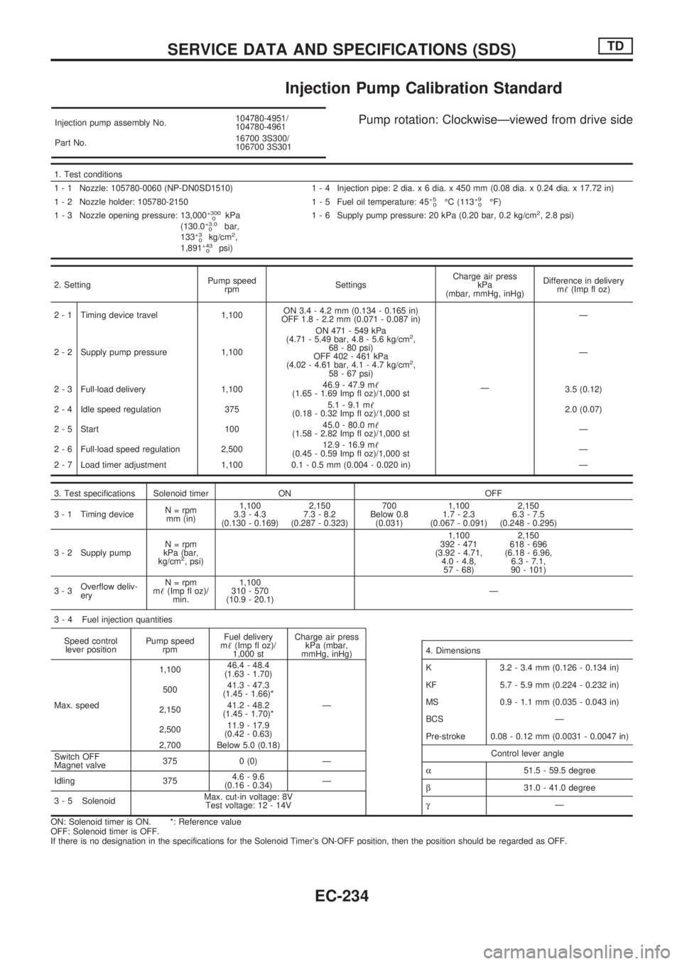
Injection Pump Calibration Standard
Injection pump assembly No.104780-4951/
104780-4961
Part No.16700 3S300/
106700 3S301Pump rotation: ClockwiseÐviewed from drive side
1. Test conditions
1 - 1 Nozzle: 105780-0060 (NP-DN0SD1510) 1 - 4 Injection pipe: 2 dia. x 6 dia. x 450 mm (0.08 dia. x 0.24 dia. x 17.72 in)
1 - 2 Nozzle holder: 105780-2150 1 - 5 Fuel oil temperature: 45
+5
0ÉC (113+9
0ÉF)
1 - 3 Nozzle opening pressure: 13,000+300
0kPa
(130.0+3.0
0bar,
133+3
0kg/cm2,
1,891+43
0psi)1 - 6 Supply pump pressure: 20 kPa (0.20 bar, 0.2 kg/cm
2, 2.8 psi)
2. SettingPump speed
rpmSettingsCharge air press
kPa
(mbar, mmHg, inHg)Difference in delivery
m!(Imp fl oz)
2 - 1 Timing device travel 1,100ON 3.4 - 4.2 mm (0.134 - 0.165 in)
OFF 1.8 - 2.2 mm (0.071 - 0.087 in)
ÐÐ
2 - 2 Supply pump pressure 1,100ON 471 - 549 kPa
(4.71 - 5.49 bar, 4.8 - 5.6 kg/cm
2,
68 - 80 psi)
OFF 402 - 461 kPa
(4.02 - 4.61 bar, 4.1 - 4.7 kg/cm
2,
58 - 67 psi)Ð
2 - 3 Full-load delivery 1,10046.9 - 47.9 m!
(1.65 - 1.69 Imp fl oz)/1,000 st3.5 (0.12)
2 - 4 Idle speed regulation 3755.1 - 9.1 m!
(0.18 - 0.32 Imp fl oz)/1,000 st2.0 (0.07)
2 - 5 Start 10045.0 - 80.0 m!
(1.58 - 2.82 Imp fl oz)/1,000 stÐ
2 - 6 Full-load speed regulation 2,50012.9 - 16.9 m!
(0.45 - 0.59 Imp fl oz)/1,000 stÐ
2 - 7 Load timer adjustment 1,100 0.1 - 0.5 mm (0.004 - 0.020 in) Ð
3. Test specifications Solenoid timer ON OFF
3 - 1 Timing deviceN = rpm
mm (in)1,100
3.3 - 4.3
(0.130 - 0.169)2,150
7.3 - 8.2
(0.287 - 0.323)700
Below 0.8
(0.031)1,100
1.7 - 2.3
(0.067 - 0.091)2,150
6.3 - 7.5
(0.248 - 0.295)
3 - 2 Supply pumpN = rpm
kPa (bar,
kg/cm
2, psi)1,100
392 - 471
(3.92 - 4.71,
4.0 - 4.8,
57 - 68)2,150
618 - 696
(6.18 - 6.96,
6.3 - 7.1,
90 - 101)
3-3Overflow deliv-
eryN = rpm
m!(Imp fl oz)/
min.1,100
310 - 570
(10.9 - 20.1)Ð
3 - 4 Fuel injection quantities
Speed control
lever positionPump speed
rpmFuel delivery
m!(Imp fl oz)/
1,000 stCharge air press
kPa (mbar,
mmHg, inHg)
Max. speed1,10046.4 - 48.4
(1.63 - 1.70)
Ð 50041.3 - 47.3
(1.45 - 1.66)*
2,15041.2 - 48.2
(1.45 - 1.70)*
2,50011.9 - 17.9
(0.42 - 0.63)
2,700 Below 5.0 (0.18)
Switch OFF
Magnet valve375 0 (0) Ð
Idling 3754.6 - 9.6
(0.16 - 0.34)Ð
3 - 5 SolenoidMax. cut-in voltage: 8V
Test voltage: 12 - 14V
ON: Solenoid timer is ON. *: Reference value
OFF: Solenoid timer is OFF.
If there is no designation in the specifications for the Solenoid Timer's ON-OFF position, then the position should be regarded as OFF.
4. Dimensions
K 3.2 - 3.4 mm (0.126 - 0.134 in)
KF 5.7 - 5.9 mm (0.224 - 0.232 in)
MS 0.9 - 1.1 mm (0.035 - 0.043 in)
BCS Ð
Pre-stroke 0.08 - 0.12 mm (0.0031 - 0.0047 in)
Control lever angle
a51.5 - 59.5 degree
b31.0 - 41.0 degree
gÐ
SERVICE DATA AND SPECIFICATIONS (SDS)TD
EC-234
Page 387 of 1659
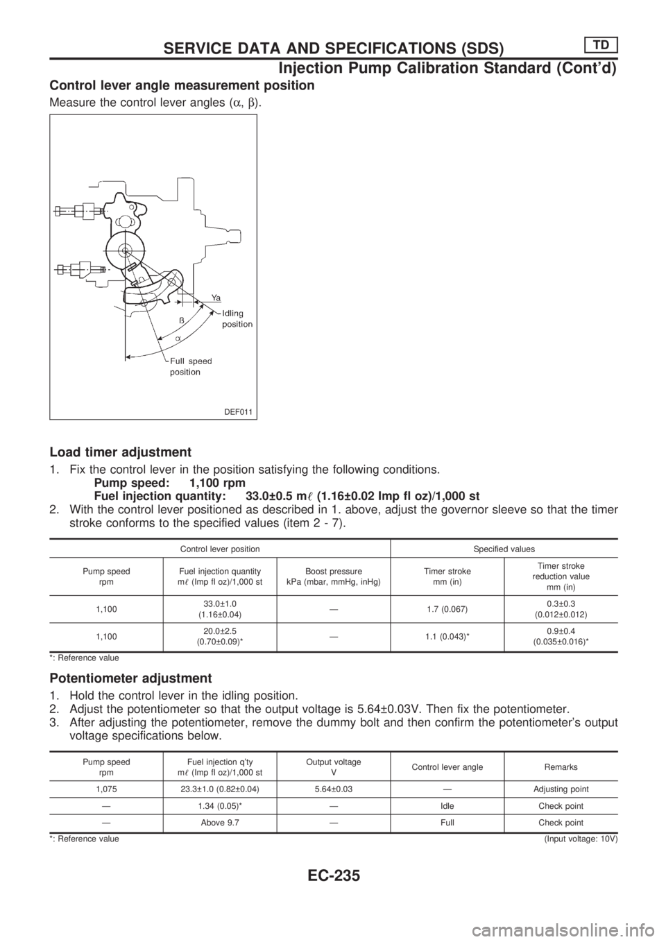
Control lever angle measurement position
Measure the control lever angles (a,b).
Load timer adjustment
1. Fix the control lever in the position satisfying the following conditions.
Pump speed: 1,100 rpm
Fuel injection quantity: 33.0 0.5 m!(1.16 0.02 Imp fl oz)/1,000 st
2. With the control lever positioned as described in 1. above, adjust the governor sleeve so that the timer
stroke conforms to the specified values (item2-7).
Control lever position Specified values
Pump speed
rpmFuel injection quantity
m!(Imp fl oz)/1,000 stBoost pressure
kPa (mbar, mmHg, inHg)Timer stroke
mm (in)Timer stroke
reduction value
mm (in)
1,10033.0 1.0
(1.16 0.04)Ð 1.7 (0.067)0.3 0.3
(0.012 0.012)
1,10020.0 2.5
(0.70 0.09)*Ð 1.1 (0.043)*0.9 0.4
(0.035 0.016)*
*: Reference value
Potentiometer adjustment
1. Hold the control lever in the idling position.
2. Adjust the potentiometer so that the output voltage is 5.64 0.03V. Then fix the potentiometer.
3. After adjusting the potentiometer, remove the dummy bolt and then confirm the potentiometer's output
voltage specifications below.
Pump speed
rpmFuel injection q'ty
m!(Imp fl oz)/1,000 stOutput voltage
VControl lever angle Remarks
1,075 23.3 1.0 (0.82 0.04) 5.64 0.03 Ð Adjusting point
Ð 1.34 (0.05)* Ð Idle Check point
Ð Above 9.7 Ð Full Check point
*: Reference value(Input voltage: 10V)
DEF011
SERVICE DATA AND SPECIFICATIONS (SDS)TD
Injection Pump Calibration Standard (Cont'd)
EC-235
Page 388 of 1659
ELECTRICAL SYSTEM
SECTION
EL
When you read wiring diagrams:
lRead GI section, ``HOW TO READ WIRING DIAGRAMS''.
When you perform trouble diagnoses, read GI section, ``HOW TO FOLLOW FLOW CHART IN
TROUBLE DIAGNOSES'' and ``HOW TO PERFORM EFFICIENT DIAGNOSIS FOR AN ELECTRI-
CAL INCIDENT''.
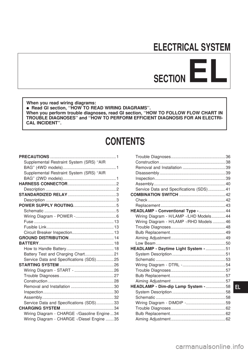
CONTENTS
PRECAUTIONS......................................................... 1
Supplemental Restraint System (SRS) ``AIR
BAG'' (4WD models).............................................. 1
Supplemental Restraint System (SRS) ``AIR
BAG'' (2WD models).............................................. 1
HARNESS CONNECTOR.......................................... 2
Description ............................................................. 2
STANDARDIZED RELAY.......................................... 3
Description ............................................................. 3
POWER SUPPLY ROUTING..................................... 5
Schematic .............................................................. 5
Wiring Diagram - POWER -................................... 6
Fuse ..................................................................... 13
Fusible Link .......................................................... 13
Circuit Breaker Inspection.................................... 13
GROUND DISTRIBUTION....................................... 14
BATTERY................................................................. 18
How to Handle Battery......................................... 18
Battery Test and Charging Chart......................... 21
Service Data and Specifications (SDS) ............... 25
STARTING SYSTEM............................................... 26
Wiring Diagram - START - .................................. 26
Trouble Diagnoses ............................................... 27
Construction ......................................................... 28
Removal and Installation ..................................... 30
Inspection ............................................................. 30
Assembly.............................................................. 32
Service Data and Specifications (SDS) ............... 33
CHARGING SYSTEM.............................................. 34
Wiring Diagram - CHARGE -/Gasoline Engine ... 34
Wiring Diagram - CHARGE -/Diesel Engine ....... 35Trouble Diagnoses ............................................... 36
Construction ......................................................... 38
Removal and Installation ..................................... 39
Disassembly ......................................................... 39
Inspection ............................................................. 39
Assembly.............................................................. 40
Service Data and Specifications (SDS) ............... 41
COMBINATION SWITCH........................................ 42
Check ................................................................... 42
Replacement ........................................................ 43
HEADLAMP - Conventional Type -....................... 44
Wiring Diagram - H/LAMP -/LHD Models ............ 44
Wiring Diagram - H/LAMP -/RHD Models ........... 46
Trouble Diagnoses ............................................... 48
Bulb Replacement................................................ 49
Aiming Adjustment ............................................... 49
Low Beam ............................................................ 50
HEADLAMP - Daytime Light System -................. 51
System Description .............................................. 51
Schematic ............................................................ 53
Wiring Diagram - DTRL - ..................................... 54
Trouble Diagnoses ............................................... 57
Bulb Replacement................................................ 57
Aiming Adjustment ............................................... 57
HEADLAMP - Dim-dip Lamp System -................. 58
System Description .............................................. 58
Schematic ............................................................ 58
Wiring Diagram - DIMDIP -.................................. 59
Trouble Diagnoses ............................................... 62
Bulb Replacement................................................ 62
Aiming Adjustment ............................................... 62
EL
Page 389 of 1659
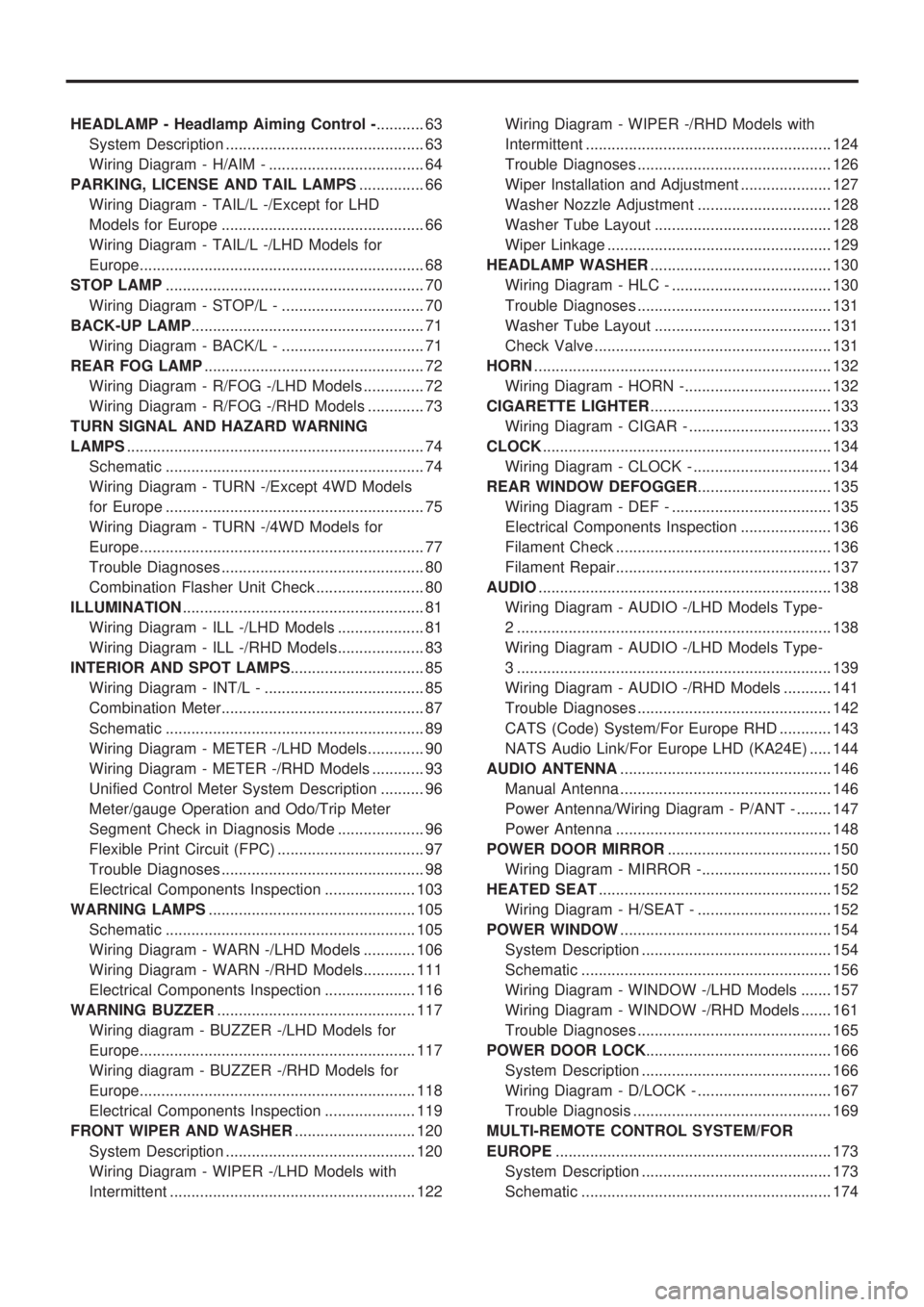
HEADLAMP - Headlamp Aiming Control -........... 63
System Description .............................................. 63
Wiring Diagram - H/AIM - .................................... 64
PARKING, LICENSE AND TAIL LAMPS............... 66
Wiring Diagram - TAIL/L -/Except for LHD
Models for Europe ............................................... 66
Wiring Diagram - TAIL/L -/LHD Models for
Europe.................................................................. 68
STOP LAMP............................................................ 70
Wiring Diagram - STOP/L - ................................. 70
BACK-UP LAMP...................................................... 71
Wiring Diagram - BACK/L - ................................. 71
REAR FOG LAMP................................................... 72
Wiring Diagram - R/FOG -/LHD Models .............. 72
Wiring Diagram - R/FOG -/RHD Models ............. 73
TURN SIGNAL AND HAZARD WARNING
LAMPS..................................................................... 74
Schematic ............................................................ 74
Wiring Diagram - TURN -/Except 4WD Models
for Europe ............................................................ 75
Wiring Diagram - TURN -/4WD Models for
Europe.................................................................. 77
Trouble Diagnoses ............................................... 80
Combination Flasher Unit Check ......................... 80
ILLUMINATION........................................................ 81
Wiring Diagram - ILL -/LHD Models .................... 81
Wiring Diagram - ILL -/RHD Models.................... 83
INTERIOR AND SPOT LAMPS............................... 85
Wiring Diagram - INT/L - ..................................... 85
Combination Meter............................................... 87
Schematic ............................................................ 89
Wiring Diagram - METER -/LHD Models............. 90
Wiring Diagram - METER -/RHD Models ............ 93
Unified Control Meter System Description .......... 96
Meter/gauge Operation and Odo/Trip Meter
Segment Check in Diagnosis Mode .................... 96
Flexible Print Circuit (FPC) .................................. 97
Trouble Diagnoses ............................................... 98
Electrical Components Inspection ..................... 103
WARNING LAMPS................................................ 105
Schematic .......................................................... 105
Wiring Diagram - WARN -/LHD Models ............ 106
Wiring Diagram - WARN -/RHD Models............ 111
Electrical Components Inspection ..................... 116
WARNING BUZZER.............................................. 117
Wiring diagram - BUZZER -/LHD Models for
Europe................................................................ 117
Wiring diagram - BUZZER -/RHD Models for
Europe................................................................ 118
Electrical Components Inspection ..................... 119
FRONT WIPER AND WASHER............................ 120
System Description ............................................ 120
Wiring Diagram - WIPER -/LHD Models with
Intermittent ......................................................... 122Wiring Diagram - WIPER -/RHD Models with
Intermittent ......................................................... 124
Trouble Diagnoses ............................................. 126
Wiper Installation and Adjustment ..................... 127
Washer Nozzle Adjustment ............................... 128
Washer Tube Layout ......................................... 128
Wiper Linkage .................................................... 129
HEADLAMP WASHER.......................................... 130
Wiring Diagram - HLC - ..................................... 130
Trouble Diagnoses ............................................. 131
Washer Tube Layout ......................................... 131
Check Valve ....................................................... 131
HORN..................................................................... 132
Wiring Diagram - HORN -.................................. 132
CIGARETTE LIGHTER.......................................... 133
Wiring Diagram - CIGAR - ................................. 133
CLOCK................................................................... 134
Wiring Diagram - CLOCK - ................................ 134
REAR WINDOW DEFOGGER............................... 135
Wiring Diagram - DEF - ..................................... 135
Electrical Components Inspection ..................... 136
Filament Check .................................................. 136
Filament Repair.................................................. 137
AUDIO.................................................................... 138
Wiring Diagram - AUDIO -/LHD Models Type-
2 ......................................................................... 138
Wiring Diagram - AUDIO -/LHD Models Type-
3 ......................................................................... 139
Wiring Diagram - AUDIO -/RHD Models ........... 141
Trouble Diagnoses ............................................. 142
CATS (Code) System/For Europe RHD ............ 143
NATS Audio Link/For Europe LHD (KA24E) ..... 144
AUDIO ANTENNA................................................. 146
Manual Antenna ................................................. 146
Power Antenna/Wiring Diagram - P/ANT - ........ 147
Power Antenna .................................................. 148
POWER DOOR MIRROR...................................... 150
Wiring Diagram - MIRROR -.............................. 150
HEATED SEAT...................................................... 152
Wiring Diagram - H/SEAT - ............................... 152
POWER WINDOW................................................. 154
System Description ............................................ 154
Schematic .......................................................... 156
Wiring Diagram - WINDOW -/LHD Models ....... 157
Wiring Diagram - WINDOW -/RHD Models ....... 161
Trouble Diagnoses ............................................. 165
POWER DOOR LOCK........................................... 166
System Description ............................................ 166
Wiring Diagram - D/LOCK - ............................... 167
Trouble Diagnosis .............................................. 169
MULTI-REMOTE CONTROL SYSTEM/FOR
EUROPE................................................................ 173
System Description ............................................ 173
Schematic .......................................................... 174
Page 390 of 1659
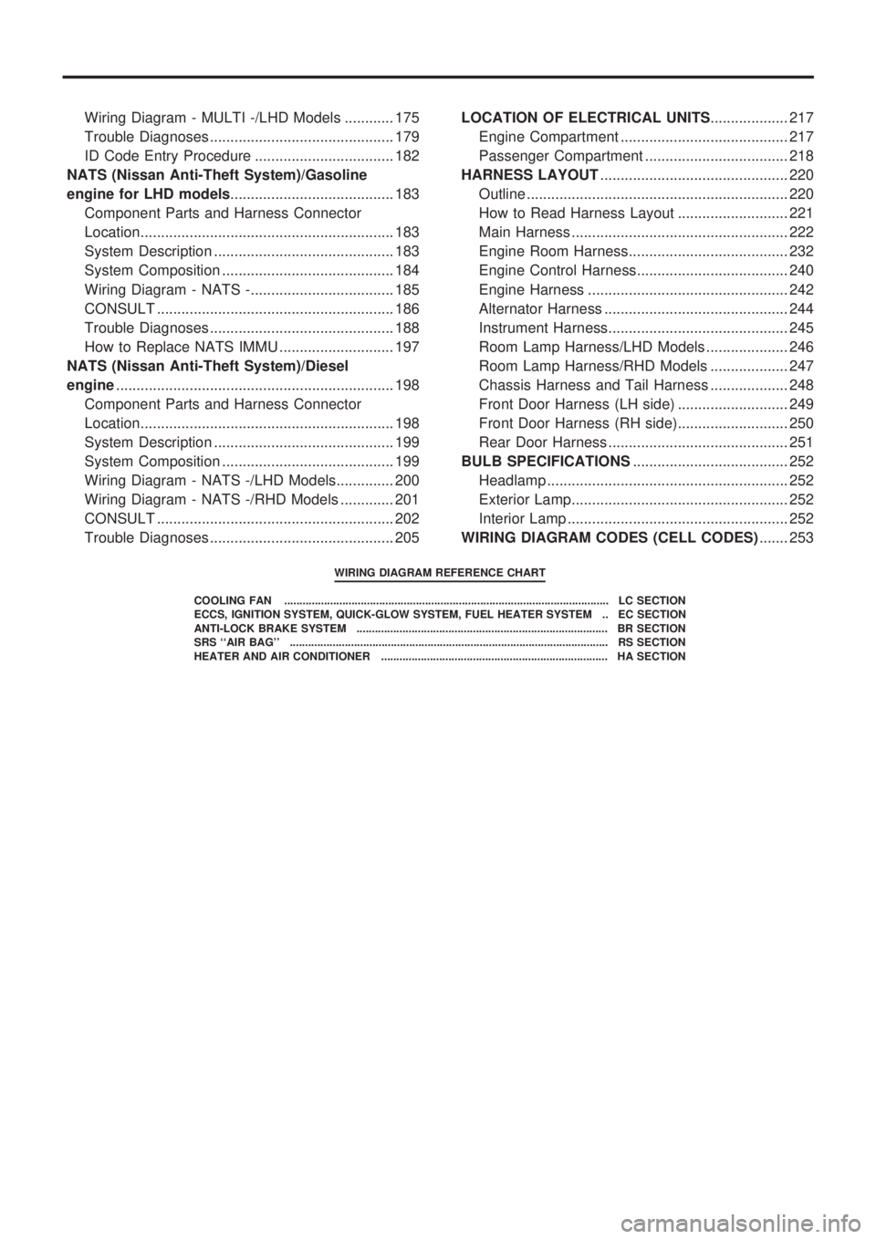
Wiring Diagram - MULTI -/LHD Models ............ 175
Trouble Diagnoses ............................................. 179
ID Code Entry Procedure .................................. 182
NATS (Nissan Anti-Theft System)/Gasoline
engine for LHD models........................................ 183
Component Parts and Harness Connector
Location.............................................................. 183
System Description ............................................ 183
System Composition .......................................... 184
Wiring Diagram - NATS -................................... 185
CONSULT .......................................................... 186
Trouble Diagnoses ............................................. 188
How to Replace NATS IMMU ............................ 197
NATS (Nissan Anti-Theft System)/Diesel
engine.................................................................... 198
Component Parts and Harness Connector
Location.............................................................. 198
System Description ............................................ 199
System Composition .......................................... 199
Wiring Diagram - NATS -/LHD Models.............. 200
Wiring Diagram - NATS -/RHD Models ............. 201
CONSULT .......................................................... 202
Trouble Diagnoses ............................................. 205LOCATION OF ELECTRICAL UNITS................... 217
Engine Compartment ......................................... 217
Passenger Compartment ................................... 218
HARNESS LAYOUT.............................................. 220
Outline ................................................................ 220
How to Read Harness Layout ........................... 221
Main Harness ..................................................... 222
Engine Room Harness....................................... 232
Engine Control Harness..................................... 240
Engine Harness ................................................. 242
Alternator Harness ............................................. 244
Instrument Harness............................................ 245
Room Lamp Harness/LHD Models .................... 246
Room Lamp Harness/RHD Models ................... 247
Chassis Harness and Tail Harness ................... 248
Front Door Harness (LH side) ........................... 249
Front Door Harness (RH side)........................... 250
Rear Door Harness ............................................ 251
BULB SPECIFICATIONS...................................... 252
Headlamp ........................................................... 252
Exterior Lamp..................................................... 252
Interior Lamp ...................................................... 252
WIRING DIAGRAM CODES (CELL CODES)....... 253
WIRING DIAGRAM REFERENCE CHART
COOLING FAN .......................................................................................................... LC SECTION
ECCS, IGNITION SYSTEM, QUICK-GLOW SYSTEM, FUEL HEATER SYSTEM .. EC SECTION
ANTI-LOCK BRAKE SYSTEM .................................................................................. BR SECTION
SRS ``AIR BAG'' ........................................................................................................ RS SECTION
HEATER AND AIR CONDITIONER .......................................................................... HA SECTION