NISSAN PICK-UP 1998 Repair Manual
Manufacturer: NISSAN, Model Year: 1998, Model line: PICK-UP, Model: NISSAN PICK-UP 1998Pages: 1659, PDF Size: 53.39 MB
Page 731 of 1659
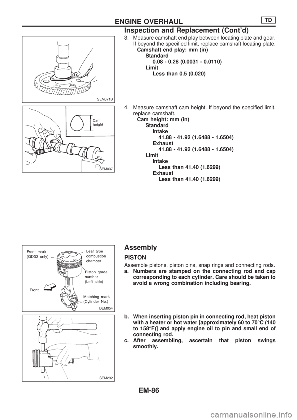
3. Measure camshaft end play between locating plate and gear.
If beyond the specified limit, replace camshaft locating plate.
Camshaft end play: mm (in)
Standard
0.08 - 0.28 (0.0031 - 0.0110)
Limit
Less than 0.5 (0.020)
4. Measure camshaft cam height. If beyond the specified limit,
replace camshaft.
Cam height: mm (in)
Standard
Intake
41.88 - 41.92 (1.6488 - 1.6504)
Exhaust
41.88 - 41.92 (1.6488 - 1.6504)
Limit
Intake
Less than 41.40 (1.6299)
Exhaust
Less than 41.40 (1.6299)
Assembly
PISTON
Assemble pistons, piston pins, snap rings and connecting rods.
a. Numbers are stamped on the connecting rod and cap
corresponding to each cylinder. Care should be taken to
avoid a wrong combination including bearing.
b. When inserting piston pin in connecting rod, heat piston
with a heater or hot water [approximately 60 to 70ÉC (140
to 158ÉF)] and apply engine oil to pin and small end of
connecting rod.
c. After assembling, ascertain that piston swings
smoothly.
SEM671B
SEM037
DEM054
SEM292
ENGINE OVERHAULTD
Inspection and Replacement (Cont'd)
EM-86
Page 732 of 1659
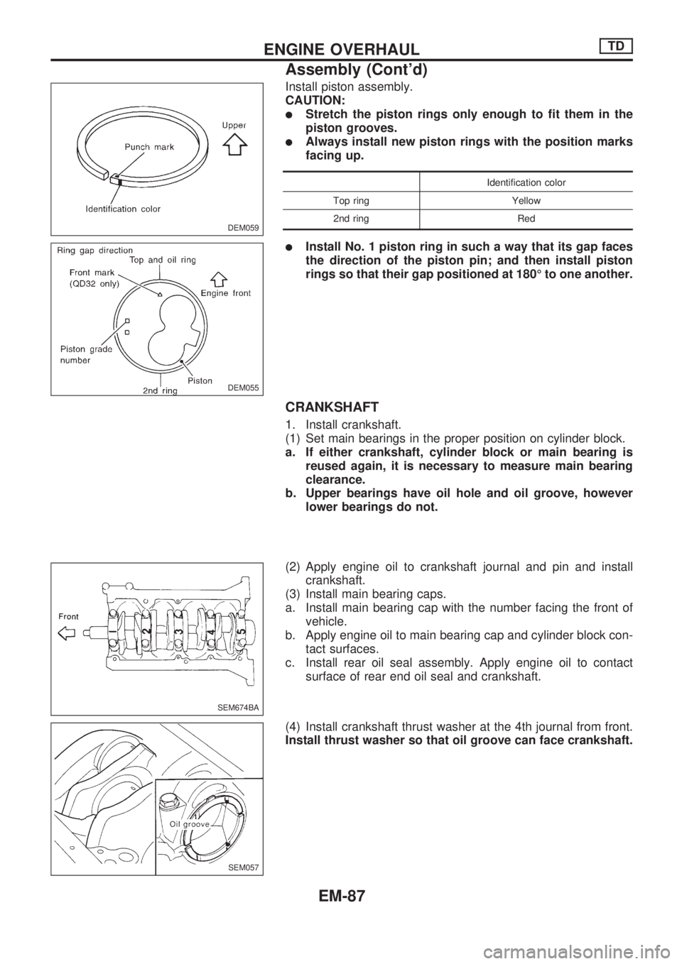
Install piston assembly.
CAUTION:
lStretch the piston rings only enough to fit them in the
piston grooves.
lAlways install new piston rings with the position marks
facing up.
Identification color
Top ring Yellow
2nd ring Red
lInstall No. 1 piston ring in such a way that its gap faces
the direction of the piston pin; and then install piston
rings so that their gap positioned at 180É to one another.
CRANKSHAFT
1. Install crankshaft.
(1) Set main bearings in the proper position on cylinder block.
a. If either crankshaft, cylinder block or main bearing is
reused again, it is necessary to measure main bearing
clearance.
b. Upper bearings have oil hole and oil groove, however
lower bearings do not.
(2) Apply engine oil to crankshaft journal and pin and install
crankshaft.
(3) Install main bearing caps.
a. Install main bearing cap with the number facing the front of
vehicle.
b. Apply engine oil to main bearing cap and cylinder block con-
tact surfaces.
c. Install rear oil seal assembly. Apply engine oil to contact
surface of rear end oil seal and crankshaft.
(4) Install crankshaft thrust washer at the 4th journal from front.
Install thrust washer so that oil groove can face crankshaft.
DEM059
DEM055
SEM674BA
SEM057
ENGINE OVERHAULTD
Assembly (Cont'd)
EM-87
Page 733 of 1659
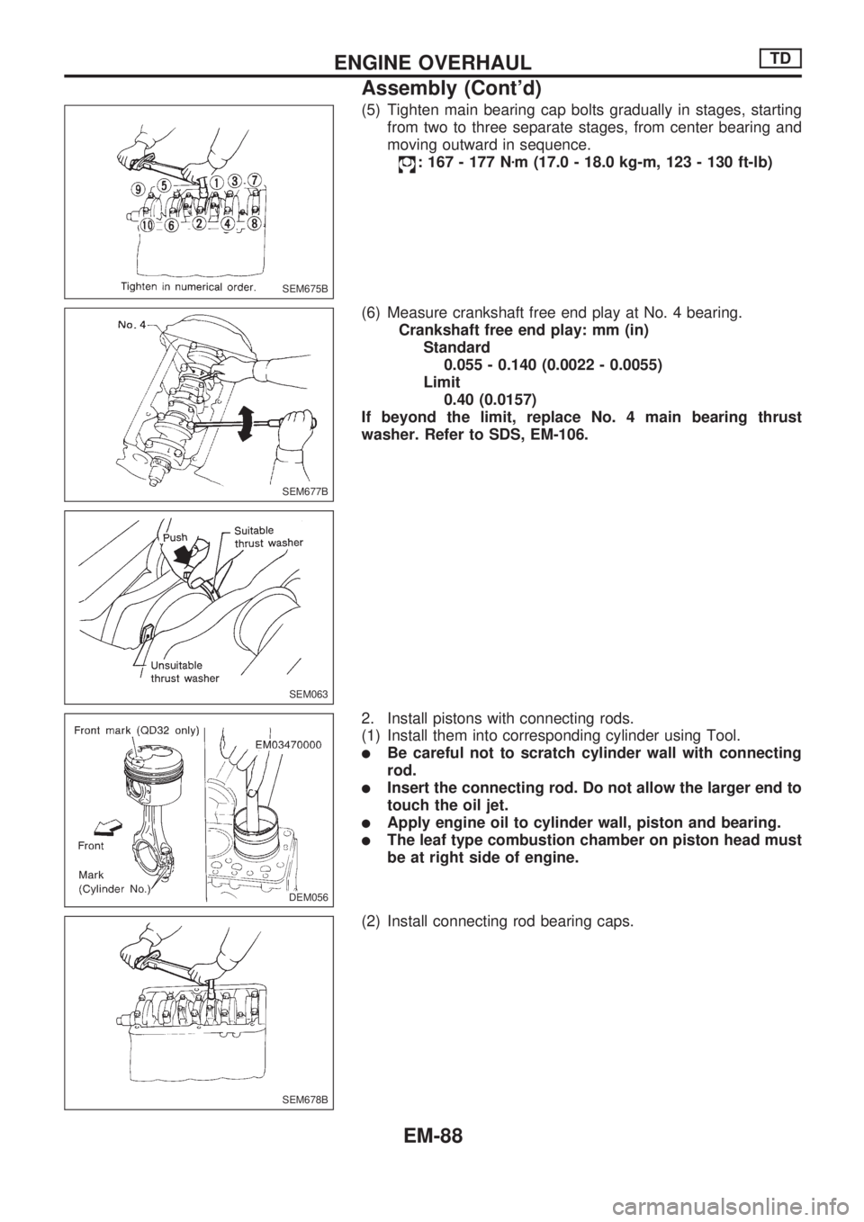
(5) Tighten main bearing cap bolts gradually in stages, starting
from two to three separate stages, from center bearing and
moving outward in sequence.
: 167 - 177 Nzm (17.0 - 18.0 kg-m, 123 - 130 ft-lb)
(6) Measure crankshaft free end play at No. 4 bearing.
Crankshaft free end play: mm (in)
Standard
0.055 - 0.140 (0.0022 - 0.0055)
Limit
0.40 (0.0157)
If beyond the limit, replace No. 4 main bearing thrust
washer. Refer to SDS, EM-106.
2. Install pistons with connecting rods.
(1) Install them into corresponding cylinder using Tool.
lBe careful not to scratch cylinder wall with connecting
rod.
lInsert the connecting rod. Do not allow the larger end to
touch the oil jet.
lApply engine oil to cylinder wall, piston and bearing.
lThe leaf type combustion chamber on piston head must
be at right side of engine.
(2) Install connecting rod bearing caps.
SEM675B
SEM677B
SEM063
DEM056.DEM056
SEM678B
ENGINE OVERHAULTD
Assembly (Cont'd)
EM-88
Page 734 of 1659
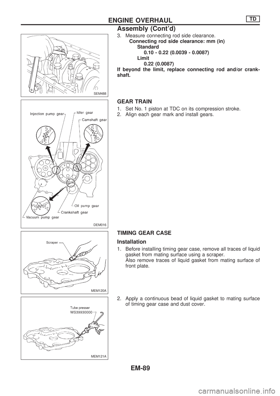
3. Measure connecting rod side clearance.
Connecting rod side clearance: mm (in)
Standard
0.10 - 0.22 (0.0039 - 0.0087)
Limit
0.22 (0.0087)
If beyond the limit, replace connecting rod and/or crank-
shaft.
GEAR TRAIN
1. Set No. 1 piston at TDC on its compression stroke.
2. Align each gear mark and install gears.
TIMING GEAR CASE
Installation
1. Before installing timing gear case, remove all traces of liquid
gasket from mating surface using a scraper.
Also remove traces of liquid gasket from mating surface of
front plate.
2. Apply a continuous bead of liquid gasket to mating surface
of timing gear case and dust cover.
SEM488
DEM016
MEM120A
MEM121A
ENGINE OVERHAULTD
Assembly (Cont'd)
EM-89
Page 735 of 1659
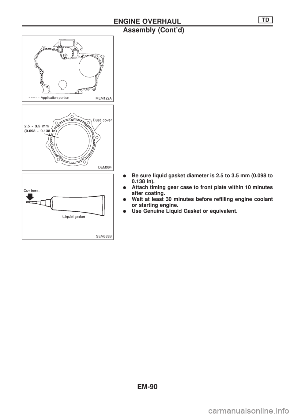
lBe sure liquid gasket diameter is 2.5 to 3.5 mm (0.098 to
0.138 in).
lAttach timing gear case to front plate within 10 minutes
after coating.
lWait at least 30 minutes before refilling engine coolant
or starting engine.
lUse Genuine Liquid Gasket or equivalent.
MEM122A
DEM064
SEM683B
ENGINE OVERHAULTD
Assembly (Cont'd)
EM-90
Page 736 of 1659
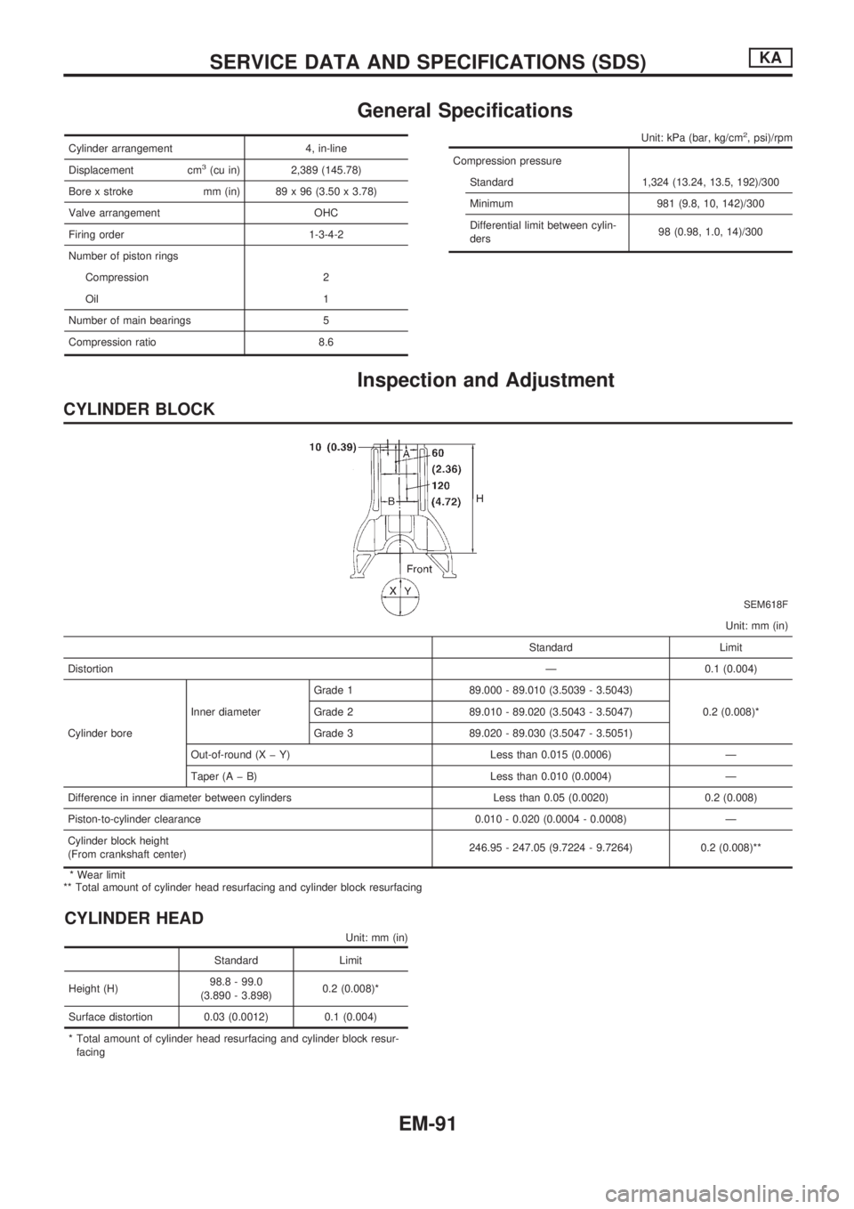
General Specifications
Cylinder arrangement 4, in-line
Displacement cm
3(cu in) 2,389 (145.78)
Bore x stroke mm (in) 89 x 96 (3.50 x 3.78)
Valve arrangement OHC
Firing order 1-3-4-2
Number of piston rings
Compression 2
Oil 1
Number of main bearings 5
Compression ratio 8.6
Unit: kPa (bar, kg/cm2, psi)/rpm
Compression pressure
Standard 1,324 (13.24, 13.5, 192)/300
Minimum 981 (9.8, 10, 142)/300
Differential limit between cylin-
ders98 (0.98, 1.0, 14)/300
Inspection and Adjustment
CYLINDER BLOCK
SEM618F
Unit: mm (in)
Standard Limit
DistortionÐ 0.1 (0.004)
Cylinder boreInner diameterGrade 1 89.000 - 89.010 (3.5039 - 3.5043)
0.2 (0.008)* Grade 2 89.010 - 89.020 (3.5043 - 3.5047)
Grade 3 89.020 - 89.030 (3.5047 - 3.5051)
Out-of-round (X þ Y) Less than 0.015 (0.0006) Ð
Taper (A þ B) Less than 0.010 (0.0004) Ð
Difference in inner diameter between cylinders Less than 0.05 (0.0020) 0.2 (0.008)
Piston-to-cylinder clearance 0.010 - 0.020 (0.0004 - 0.0008) Ð
Cylinder block height
(From crankshaft center)246.95 - 247.05 (9.7224 - 9.7264) 0.2 (0.008)**
* Wear limit
** Total amount of cylinder head resurfacing and cylinder block resurfacing
CYLINDER HEAD
Unit: mm (in)
Standard Limit
Height (H)98.8 - 99.0
(3.890 - 3.898)0.2 (0.008)*
Surface distortion 0.03 (0.0012) 0.1 (0.004)
* Total amount of cylinder head resurfacing and cylinder block resur-
facing
SERVICE DATA AND SPECIFICATIONS (SDS)KA
EM-91
Page 737 of 1659
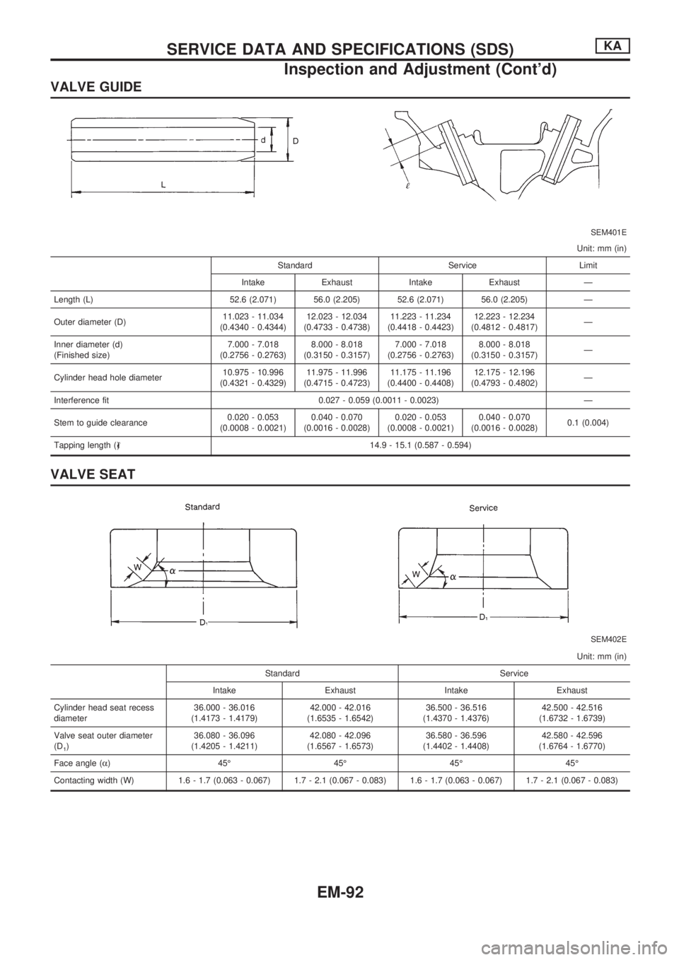
VALVE GUIDE
SEM401E
Unit: mm (in)
Standard Service Limit
Intake Exhaust Intake Exhaust Ð
Length (L) 52.6 (2.071) 56.0 (2.205) 52.6 (2.071) 56.0 (2.205) Ð
Outer diameter (D)11.023 - 11.034
(0.4340 - 0.4344)12.023 - 12.034
(0.4733 - 0.4738)11.223 - 11.234
(0.4418 - 0.4423)12.223 - 12.234
(0.4812 - 0.4817)Ð
Inner diameter (d)
(Finished size)7.000 - 7.018
(0.2756 - 0.2763)8.000 - 8.018
(0.3150 - 0.3157)7.000 - 7.018
(0.2756 - 0.2763)8.000 - 8.018
(0.3150 - 0.3157)Ð
Cylinder head hole diameter10.975 - 10.996
(0.4321 - 0.4329)11.975 - 11.996
(0.4715 - 0.4723)11.175 - 11.196
(0.4400 - 0.4408)12.175 - 12.196
(0.4793 - 0.4802)Ð
Interference fit 0.027 - 0.059 (0.0011 - 0.0023) Ð
Stem to guide clearance0.020 - 0.053
(0.0008 - 0.0021)0.040 - 0.070
(0.0016 - 0.0028)0.020 - 0.053
(0.0008 - 0.0021)0.040 - 0.070
(0.0016 - 0.0028)0.1 (0.004)
Tapping length (,) 14.9 - 15.1 (0.587 - 0.594)
VALVE SEAT
SEM402E
Unit: mm (in)
Standard Service
Intake Exhaust Intake Exhaust
Cylinder head seat recess
diameter36.000 - 36.016
(1.4173 - 1.4179)42.000 - 42.016
(1.6535 - 1.6542)36.500 - 36.516
(1.4370 - 1.4376)42.500 - 42.516
(1.6732 - 1.6739)
Valve seat outer diameter
(D
1)36.080 - 36.096
(1.4205 - 1.4211)42.080 - 42.096
(1.6567 - 1.6573)36.580 - 36.596
(1.4402 - 1.4408)42.580 - 42.596
(1.6764 - 1.6770)
Face angle (a) 45É 45É 45É 45É
Contacting width (W) 1.6 - 1.7 (0.063 - 0.067) 1.7 - 2.1 (0.067 - 0.083) 1.6 - 1.7 (0.063 - 0.067) 1.7 - 2.1 (0.067 - 0.083)
SERVICE DATA AND SPECIFICATIONS (SDS)KA
Inspection and Adjustment (Cont'd)
EM-92
Page 738 of 1659
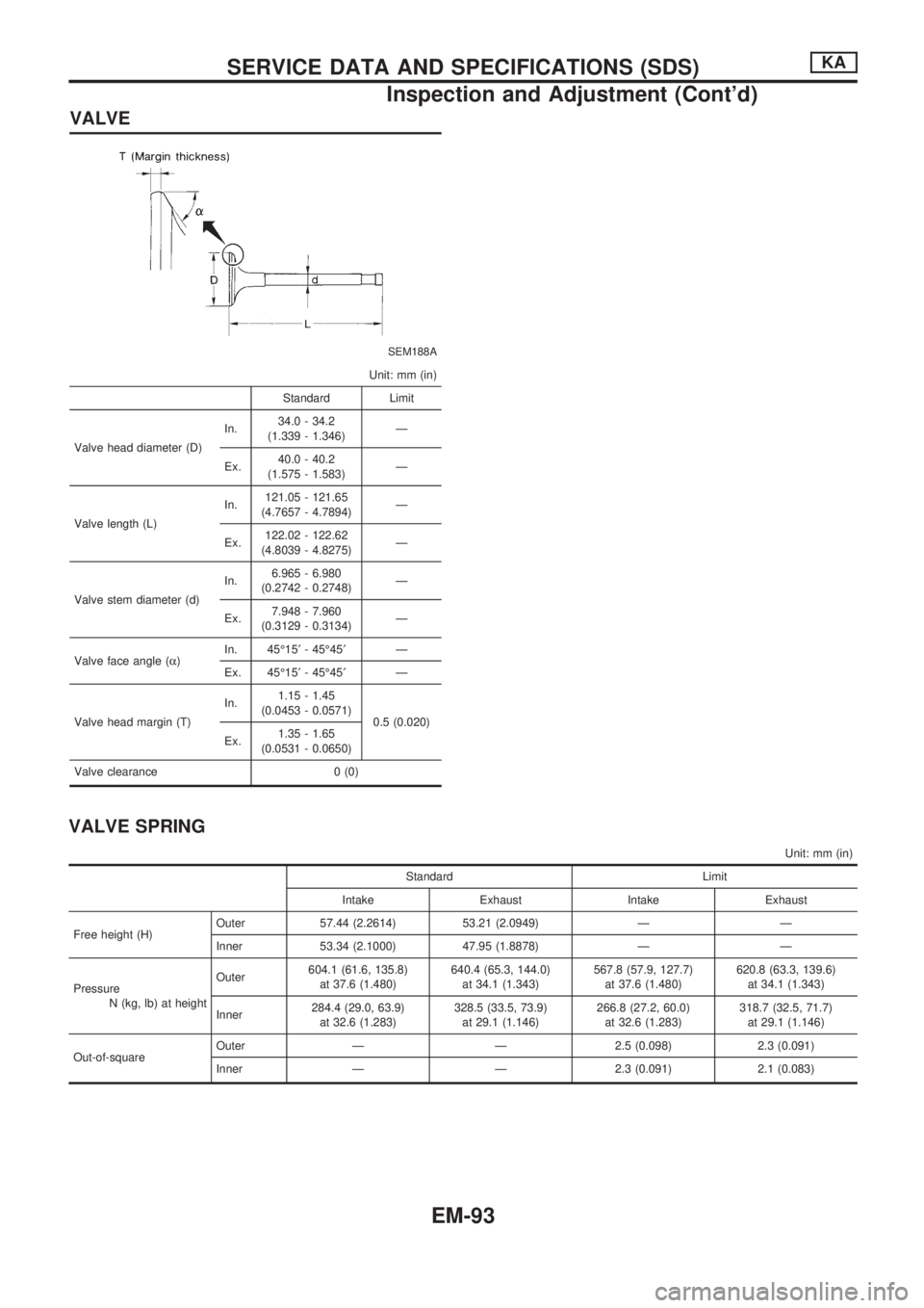
VALVE
SEM188A
Unit: mm (in)
Standard Limit
Valve head diameter (D)In.34.0 - 34.2
(1.339 - 1.346)Ð
Ex.40.0 - 40.2
(1.575 - 1.583)Ð
Valve length (L)In.121.05 - 121.65
(4.7657 - 4.7894)Ð
Ex.122.02 - 122.62
(4.8039 - 4.8275)Ð
Valve stem diameter (d)In.6.965 - 6.980
(0.2742 - 0.2748)Ð
Ex.7.948 - 7.960
(0.3129 - 0.3134)Ð
Valve face angle (a)In. 45É15¢- 45É45¢Ð
Ex. 45É15¢- 45É45¢Ð
Valve head margin (T)In.1.15 - 1.45
(0.0453 - 0.0571)
0.5 (0.020)
Ex.1.35 - 1.65
(0.0531 - 0.0650)
Valve clearance 0 (0)
VALVE SPRING
Unit: mm (in)
Standard Limit
Intake Exhaust Intake Exhaust
Free height (H)Outer 57.44 (2.2614) 53.21 (2.0949) Ð Ð
Inner 53.34 (2.1000) 47.95 (1.8878) Ð Ð
Pressure
N (kg, lb) at heightOuter604.1 (61.6, 135.8)
at 37.6 (1.480)640.4 (65.3, 144.0)
at 34.1 (1.343)567.8 (57.9, 127.7)
at 37.6 (1.480)620.8 (63.3, 139.6)
at 34.1 (1.343)
Inner284.4 (29.0, 63.9)
at 32.6 (1.283)328.5 (33.5, 73.9)
at 29.1 (1.146)266.8 (27.2, 60.0)
at 32.6 (1.283)318.7 (32.5, 71.7)
at 29.1 (1.146)
Out-of-squareOuter Ð Ð 2.5 (0.098) 2.3 (0.091)
Inner Ð Ð 2.3 (0.091) 2.1 (0.083)
SERVICE DATA AND SPECIFICATIONS (SDS)KA
Inspection and Adjustment (Cont'd)
EM-93
Page 739 of 1659
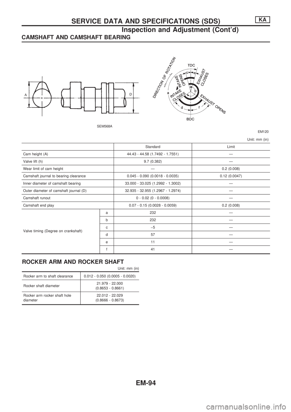
CAMSHAFT AND CAMSHAFT BEARING
SEM568A
EM120
Unit: mm (in)
Standard Limit
Cam height (A) 44.43 - 44.58 (1.7492 - 1.7551) Ð
Valve lift (h) 9.7 (0.382) Ð
Wear limit of cam height Ð 0.2 (0.008)
Camshaft journal to bearing clearance 0.045 - 0.090 (0.0018 - 0.0035) 0.12 (0.0047)
Inner diameter of camshaft bearing 33.000 - 33.025 (1.2992 - 1.3002) Ð
Outer diameter of camshaft journal (D) 32.935 - 32.955 (1.2967 - 1.2974) Ð
Camshaft runout 0 - 0.02 (0 - 0.0008) Ð
Camshaft end play 0.07 - 0.15 (0.0028 - 0.0059) 0.2 (0.008)
Valve timing (Degree on crankshaft)a 232 Ð
b 232 Ð
cþ5 Ð
d57 Ð
e11 Ð
f41 Ð
ROCKER ARM AND ROCKER SHAFT
Unit: mm (in)
Rocker arm to shaft clearance 0.012 - 0.050 (0.0005 - 0.0020)
Rocker shaft diameter21.979 - 22.000
(0.8653 - 0.8661)
Rocker arm rocker shaft hole
diameter22.012 - 22.029
(0.8666 - 0.8673)
SERVICE DATA AND SPECIFICATIONS (SDS)KA
Inspection and Adjustment (Cont'd)
EM-94
Page 740 of 1659
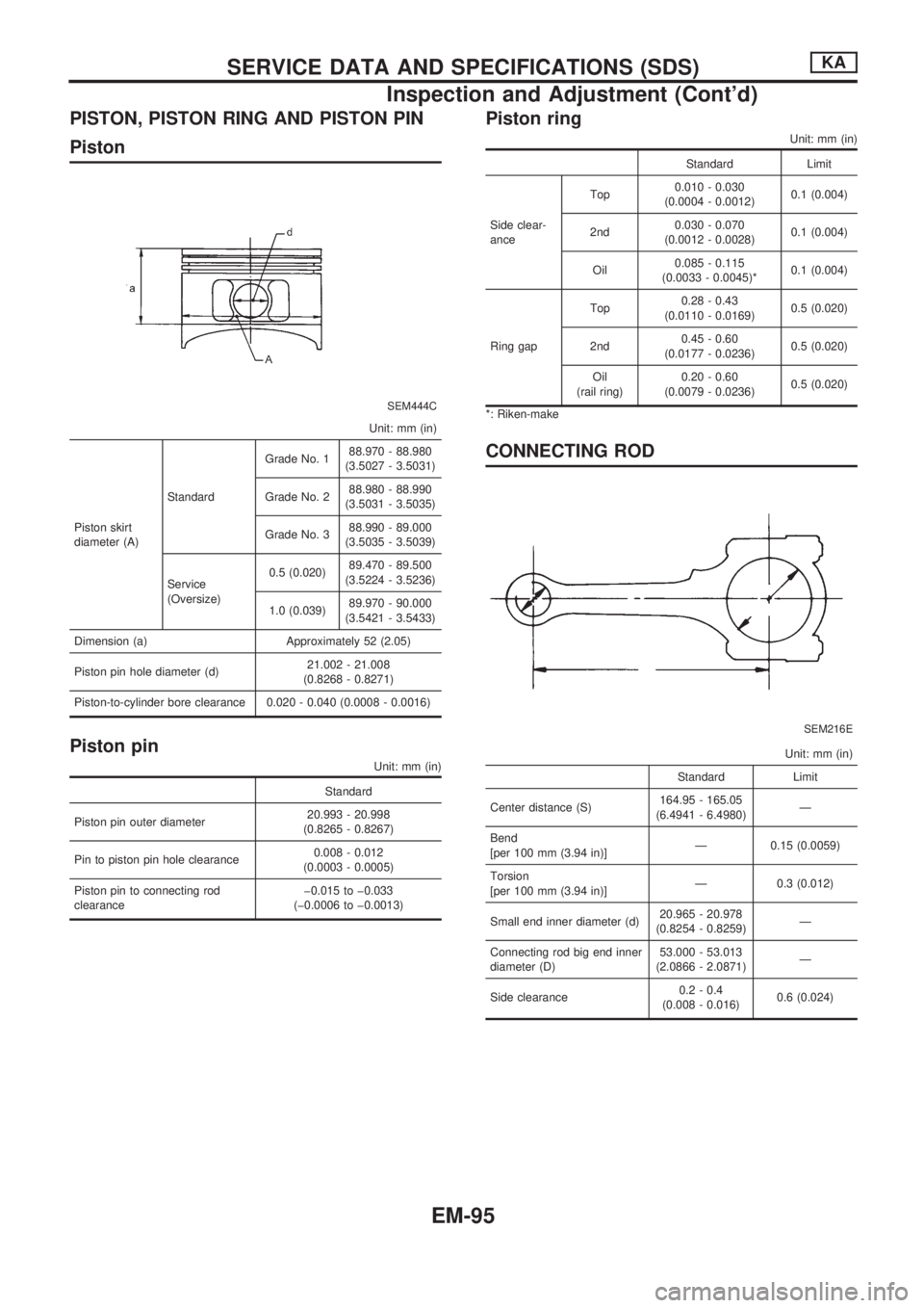
PISTON, PISTON RING AND PISTON PIN
Piston
SEM444C
Unit: mm (in)
Piston skirt
diameter (A)StandardGrade No. 188.970 - 88.980
(3.5027 - 3.5031)
Grade No. 288.980 - 88.990
(3.5031 - 3.5035)
Grade No. 388.990 - 89.000
(3.5035 - 3.5039)
Service
(Oversize)0.5 (0.020)89.470 - 89.500
(3.5224 - 3.5236)
1.0 (0.039)89.970 - 90.000
(3.5421 - 3.5433)
Dimension (a) Approximately 52 (2.05)
Piston pin hole diameter (d)21.002 - 21.008
(0.8268 - 0.8271)
Piston-to-cylinder bore clearance 0.020 - 0.040 (0.0008 - 0.0016)
Piston pin
Unit: mm (in)
Standard
Piston pin outer diameter20.993 - 20.998
(0.8265 - 0.8267)
Pin to piston pin hole clearance0.008 - 0.012
(0.0003 - 0.0005)
Piston pin to connecting rod
clearanceþ0.015 to þ0.033
(þ0.0006 to þ0.0013)
Piston ring
Unit: mm (in)
Standard Limit
Side clear-
anceTop0.010 - 0.030
(0.0004 - 0.0012)0.1 (0.004)
2nd0.030 - 0.070
(0.0012 - 0.0028)0.1 (0.004)
Oil0.085 - 0.115
(0.0033 - 0.0045)*0.1 (0.004)
Ring gapTop0.28 - 0.43
(0.0110 - 0.0169)0.5 (0.020)
2nd0.45 - 0.60
(0.0177 - 0.0236)0.5 (0.020)
Oil
(rail ring)0.20 - 0.60
(0.0079 - 0.0236)0.5 (0.020)
*: Riken-make
CONNECTING ROD
SEM216E
Unit: mm (in)
Standard Limit
Center distance (S)164.95 - 165.05
(6.4941 - 6.4980)Ð
Bend
[per 100 mm (3.94 in)]Ð 0.15 (0.0059)
Torsion
[per 100 mm (3.94 in)]Ð 0.3 (0.012)
Small end inner diameter (d)20.965 - 20.978
(0.8254 - 0.8259)Ð
Connecting rod big end inner
diameter (D)53.000 - 53.013
(2.0866 - 2.0871)Ð
Side clearance0.2 - 0.4
(0.008 - 0.016)0.6 (0.024)
SERVICE DATA AND SPECIFICATIONS (SDS)KA
Inspection and Adjustment (Cont'd)
EM-95