NISSAN PICK-UP 1998 Repair Manual
Manufacturer: NISSAN, Model Year: 1998, Model line: PICK-UP, Model: NISSAN PICK-UP 1998Pages: 1659, PDF Size: 53.39 MB
Page 721 of 1659
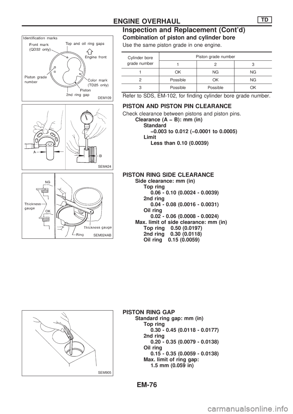
Combination of piston and cylinder bore
Use the same piston grade in one engine.
Cylinder bore
grade numberPiston grade number
123
1OKNGNG
2 Possible OK NG
3 Possible Possible OK
Refer to SDS, EM-102, for finding cylinder bore grade number.
PISTON AND PISTON PIN CLEARANCE
Check clearance between pistons and piston pins.
Clearance (A þ B): mm (in)
Standard
þ0.003 to 0.012 (þ0.0001 to 0.0005)
Limit
Less than 0.10 (0.0039)
PISTON RING SIDE CLEARANCE
Side clearance: mm (in)
Top ring
0.06 - 0.10 (0.0024 - 0.0039)
2nd ring
0.04 - 0.08 (0.0016 - 0.0031)
Oil ring
0.02 - 0.06 (0.0008 - 0.0024)
Max. limit of side clearance: mm (in)
Top ring 0.50 (0.0197)
2nd ring 0.30 (0.0118)
Oil ring 0.15 (0.0059)
PISTON RING GAP
Standard ring gap: mm (in)
Top ring
0.30 - 0.45 (0.0118 - 0.0177)
2nd ring
0.20 - 0.35 (0.0079 - 0.0138)
Oil ring
0.15 - 0.35 (0.0059 - 0.0138)
Max. limit of ring gap:
1.5 mm (0.059 in)
DEM109
SEM424
SEM024AB
SEM905
ENGINE OVERHAULTD
Inspection and Replacement (Cont'd)
EM-76
Page 722 of 1659
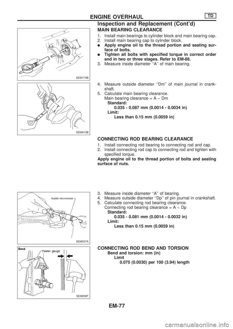
MAIN BEARING CLEARANCE
1. Install main bearings to cylinder block and main bearing cap.
2. Install main bearing cap to cylinder block.
lApply engine oil to the thread portion and seating sur-
face of bolts.
lTighten all bolts with specified torque in correct order
and in two or three stages. Refer to EM-88.
3. Measure inside diameter ``A'' of main bearing.
4. Measure outside diameter ``Dm'' of main journal in crank-
shaft.
5. Calculate main bearing clearance.
Main bearing clearance=AþDm
Standard:
0.035 - 0.087 mm (0.0014 - 0.0034 in)
Limit:
Less than 0.15 mm (0.0059 in)
CONNECTING ROD BEARING CLEARANCE
1. Install connecting rod bearing to connecting rod and cap.
2. Install connecting rod cap to connecting rod and tighten with
specified torque.
Apply engine oil to the thread portion of bolts and seating
surface of nuts.
3. Measure inside diameter ``A'' of bearing.
4. Measure outside diameter ``Dp'' of pin journal in crankshaft.
5. Calculate connecting rod bearing clearance.
Connecting rod bearing clearance=AþDp
Standard:
0.035 - 0.081 mm (0.0014 - 0.0032 in)
Limit:
Less than 0.15 mm (0.0059 in)
CONNECTING ROD BEND AND TORSION
Bend and torsion: mm (in)
Limit
0.075 (0.0030) per 100 (3.94) length
SEM174B
SEM413B
SEM507A
SEM038F
ENGINE OVERHAULTD
Inspection and Replacement (Cont'd)
EM-77
Page 723 of 1659
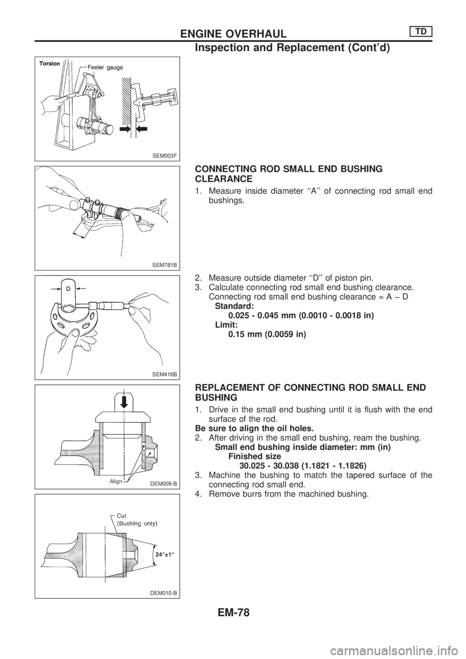
CONNECTING ROD SMALL END BUSHING
CLEARANCE
1. Measure inside diameter ``A'' of connecting rod small end
bushings.
2. Measure outside diameter ``D'' of piston pin.
3. Calculate connecting rod small end bushing clearance.
Connecting rod small end bushing clearance=AþD
Standard:
0.025 - 0.045 mm (0.0010 - 0.0018 in)
Limit:
0.15 mm (0.0059 in)
REPLACEMENT OF CONNECTING ROD SMALL END
BUSHING
1. Drive in the small end bushing until it is flush with the end
surface of the rod.
Be sure to align the oil holes.
2. After driving in the small end bushing, ream the bushing.
Small end bushing inside diameter: mm (in)
Finished size
30.025 - 30.038 (1.1821 - 1.1826)
3. Machine the bushing to match the tapered surface of the
connecting rod small end.
4. Remove burrs from the machined bushing.
SEM003F
SEM781B
SEM416B
DEM009-B
DEM010-B
ENGINE OVERHAULTD
Inspection and Replacement (Cont'd)
EM-78
Page 724 of 1659
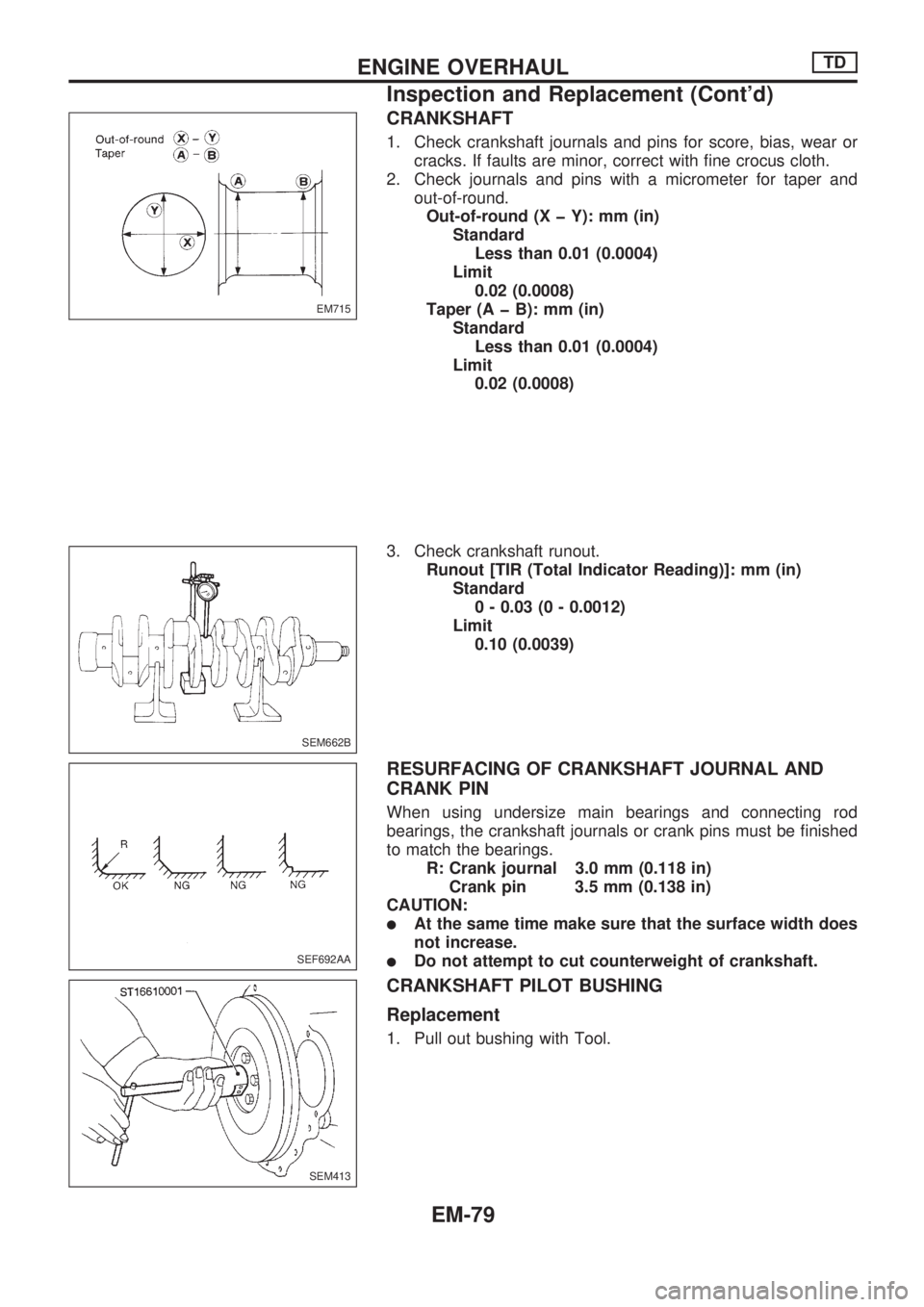
CRANKSHAFT
1. Check crankshaft journals and pins for score, bias, wear or
cracks. If faults are minor, correct with fine crocus cloth.
2. Check journals and pins with a micrometer for taper and
out-of-round.
Out-of-round (X þ Y): mm (in)
Standard
Less than 0.01 (0.0004)
Limit
0.02 (0.0008)
Taper (A þ B): mm (in)
Standard
Less than 0.01 (0.0004)
Limit
0.02 (0.0008)
3. Check crankshaft runout.
Runout [TIR (Total Indicator Reading)]: mm (in)
Standard
0 - 0.03 (0 - 0.0012)
Limit
0.10 (0.0039)
RESURFACING OF CRANKSHAFT JOURNAL AND
CRANK PIN
When using undersize main bearings and connecting rod
bearings, the crankshaft journals or crank pins must be finished
to match the bearings.
R: Crank journal 3.0 mm (0.118 in)
Crank pin 3.5 mm (0.138 in)
CAUTION:
lAt the same time make sure that the surface width does
not increase.
lDo not attempt to cut counterweight of crankshaft.
CRANKSHAFT PILOT BUSHING
Replacement
1. Pull out bushing with Tool.
EM715
SEM662B
SEF692AA
SEM413
ENGINE OVERHAULTD
Inspection and Replacement (Cont'd)
EM-79
Page 725 of 1659
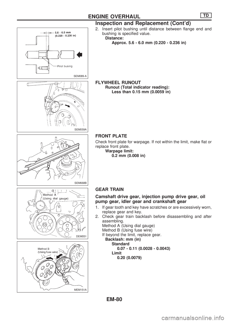
2. Insert pilot bushing until distance between flange end and
bushing is specified value.
Distance:
Approx. 5.6 - 6.0 mm (0.220 - 0.236 in)
FLYWHEEL RUNOUT
Runout (Total indicator reading):
Less than 0.15 mm (0.0059 in)
FRONT PLATE
Check front plate for warpage. If not within the limit, make flat or
replace front plate.
Warpage limit:
0.2 mm (0.008 in)
GEAR TRAIN
Camshaft drive gear, injection pump drive gear, oil
pump gear, idler gear and crankshaft gear
1. If gear tooth and key have scratches or are excessively worn,
replace gear and key.
2. Check gear train backlash before disassembling and after
assembling.
Method A (Using dial gauge)
Method B (Using fuse wire)
If beyond the limit, replace gear.
Backlash: mm (in)
Standard
0.07 - 0.11 (0.0028 - 0.0043)
Limit
0.20 (0.0079)
SEM089-A
SEM059A
SEM668B
DEM051
MEM151A
ENGINE OVERHAULTD
Inspection and Replacement (Cont'd)
EM-80
Page 726 of 1659
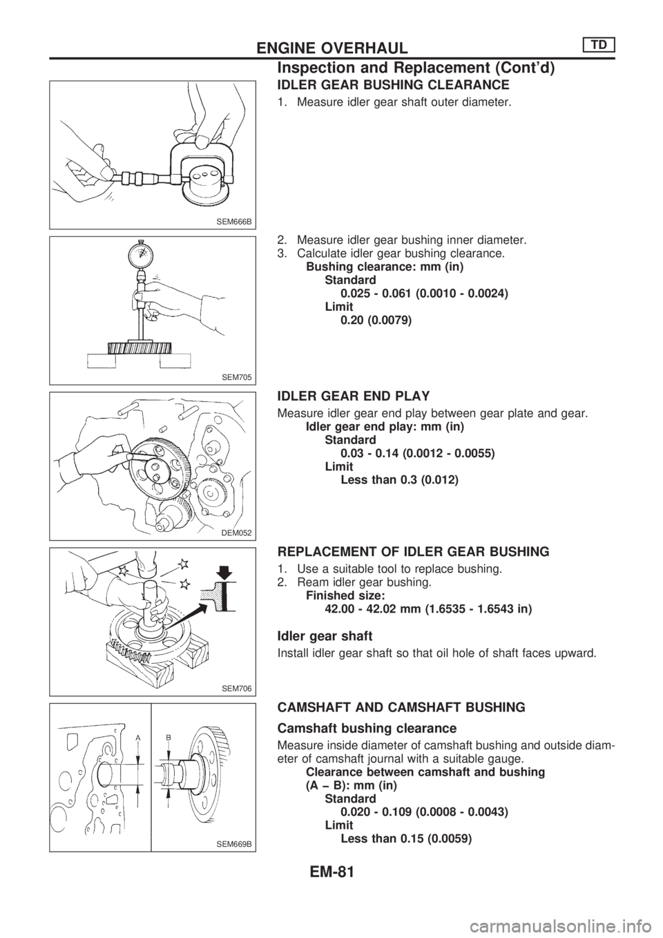
IDLER GEAR BUSHING CLEARANCE
1. Measure idler gear shaft outer diameter.
2. Measure idler gear bushing inner diameter.
3. Calculate idler gear bushing clearance.
Bushing clearance: mm (in)
Standard
0.025 - 0.061 (0.0010 - 0.0024)
Limit
0.20 (0.0079)
IDLER GEAR END PLAY
Measure idler gear end play between gear plate and gear.
Idler gear end play: mm (in)
Standard
0.03 - 0.14 (0.0012 - 0.0055)
Limit
Less than 0.3 (0.012)
REPLACEMENT OF IDLER GEAR BUSHING
1. Use a suitable tool to replace bushing.
2. Ream idler gear bushing.
Finished size:
42.00 - 42.02 mm (1.6535 - 1.6543 in)
Idler gear shaft
Install idler gear shaft so that oil hole of shaft faces upward.
CAMSHAFT AND CAMSHAFT BUSHING
Camshaft bushing clearance
Measure inside diameter of camshaft bushing and outside diam-
eter of camshaft journal with a suitable gauge.
Clearance between camshaft and bushing
(A þ B): mm (in)
Standard
0.020 - 0.109 (0.0008 - 0.0043)
Limit
Less than 0.15 (0.0059)
SEM666B
SEM705
DEM052
SEM706
SEM669B
ENGINE OVERHAULTD
Inspection and Replacement (Cont'd)
EM-81
Page 727 of 1659
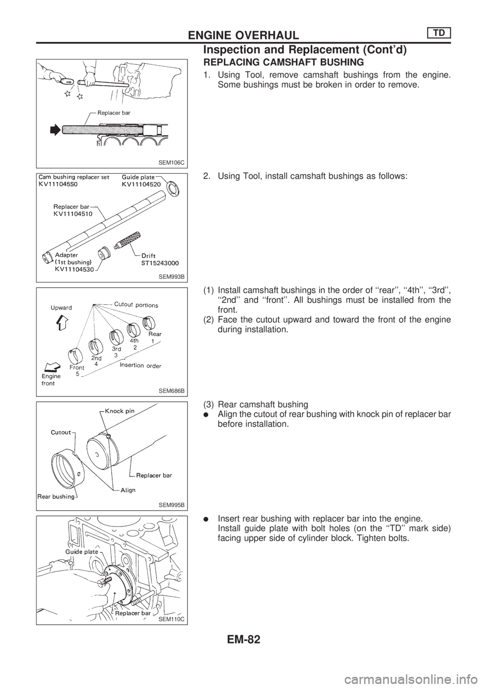
REPLACING CAMSHAFT BUSHING
1. Using Tool, remove camshaft bushings from the engine.
Some bushings must be broken in order to remove.
2. Using Tool, install camshaft bushings as follows:
(1) Install camshaft bushings in the order of ``rear'', ``4th'', ``3rd'',
``2nd'' and ``front''. All bushings must be installed from the
front.
(2) Face the cutout upward and toward the front of the engine
during installation.
(3) Rear camshaft bushing
lAlign the cutout of rear bushing with knock pin of replacer bar
before installation.
lInsert rear bushing with replacer bar into the engine.
Install guide plate with bolt holes (on the ``TD'' mark side)
facing upper side of cylinder block. Tighten bolts.
SEM106C
SEM993B
SEM686B
SEM995B
SEM110C
ENGINE OVERHAULTD
Inspection and Replacement (Cont'd)
EM-82
Page 728 of 1659
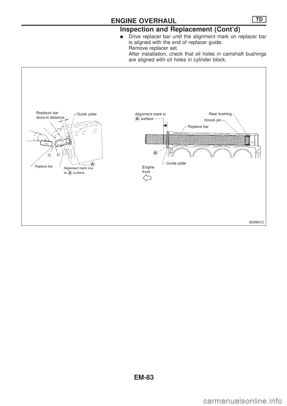
lDrive replacer bar until the alignment mark on replacer bar
is aligned with the end of replacer guide.
Remove replacer set.
After installation, check that oil holes in camshaft bushings
are aligned with oil holes in cylinder block.
SEM601C
ENGINE OVERHAULTD
Inspection and Replacement (Cont'd)
EM-83
Page 729 of 1659
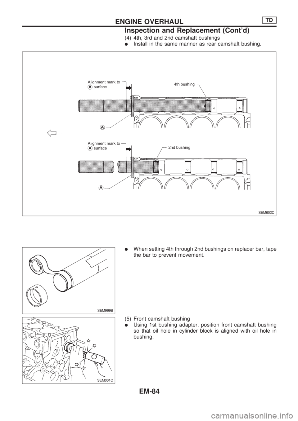
(4) 4th, 3rd and 2nd camshaft bushings
lInstall in the same manner as rear camshaft bushing.
lWhen setting 4th through 2nd bushings on replacer bar, tape
the bar to prevent movement.
(5) Front camshaft bushing
lUsing 1st bushing adapter, position front camshaft bushing
so that oil hole in cylinder block is aligned with oil hole in
bushing.
SEM602C
SEM999B
SEM001C
ENGINE OVERHAULTD
Inspection and Replacement (Cont'd)
EM-84
Page 730 of 1659
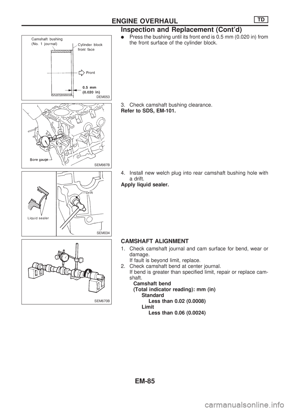
lPress the bushing until its front end is 0.5 mm (0.020 in) from
the front surface of the cylinder block.
3. Check camshaft bushing clearance.
Refer to SDS, EM-101.
4. Install new welch plug into rear camshaft bushing hole with
a drift.
Apply liquid sealer.
CAMSHAFT ALIGNMENT
1. Check camshaft journal and cam surface for bend, wear or
damage.
If fault is beyond limit, replace.
2. Check camshaft bend at center journal.
If bend is greater than specified limit, repair or replace cam-
shaft.
Camshaft bend
(Total indicator reading): mm (in)
Standard
Less than 0.02 (0.0008)
Limit
Less than 0.06 (0.0024)
DEM053
SEM987B
SEM034
SEM670B
ENGINE OVERHAULTD
Inspection and Replacement (Cont'd)
EM-85