NISSAN PICK-UP 1999 Repair Manual
Manufacturer: NISSAN, Model Year: 1999, Model line: PICK-UP, Model: NISSAN PICK-UP 1999Pages: 666, PDF Size: 16.21 MB
Page 191 of 666
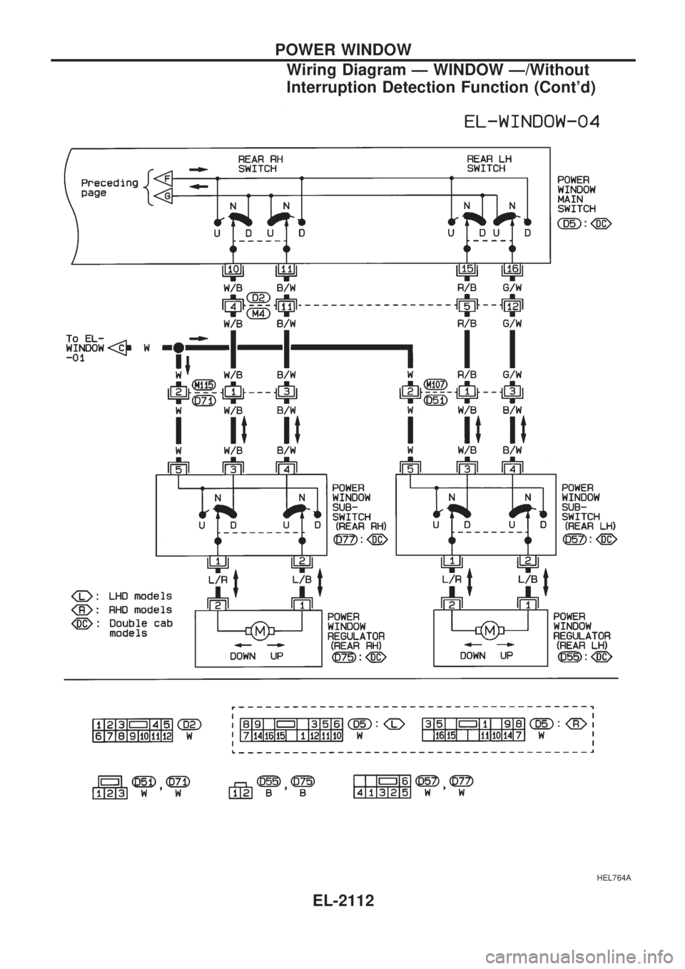
HEL764A
POWER WINDOW
Wiring Diagram Ð WINDOW Ð/Without
Interruption Detection Function (Cont'd)
EL-2112
Page 192 of 666
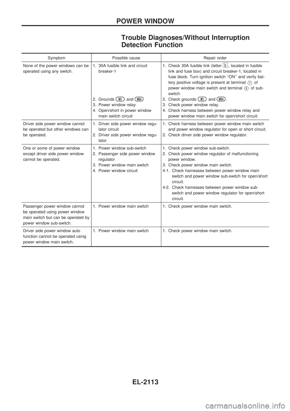
Trouble Diagnoses/Without Interruption
Detection Function
Symptom Possible cause Repair order
None of the power windows can be
operated using any switch.1. 30A fusible link and circuit
breaker-1
2. Grounds
M1andM54
3. Power window relay
4. Open/short in power window
main switch circuit1. Check 30A fusible link (letter
b, located in fusible
link and fuse box) and circuit breaker-1, located in
fuse block. Turn ignition switch ``ON'' and verify bat-
tery positive voltage is present at terminal
V1of
power window main switch and terminal
V5of sub-
switch.
2. Check grounds
M1andM54.
3. Check power window relay.
4. Check harness between power window relay and
power window main switch for open/short circuit.
Driver side power window cannot
be operated but other windows can
be operated.1. Driver side power window regu-
lator circuit
2. Driver side power window regu-
lator1. Check harness between power window main switch
and power window regulator for open or short circuit.
2. Check driver side power window regulator.
One or some of power window
except driver side power window
cannot be operated.1. Power window sub-switch
2. Passenger side power window
regulator
3. Power window main switch
4. Power window circuit1. Check power window sub-switch.
2. Check power window regulator of malfunctioning
power window.
3. Check power window main switch.
4-1. Check harnesses between power window main
switch and power window sub-switch for open/short
circuit.
4-2. Check harnesses between power window sub-
switch and power window regulator for open/short
circuit.
Passenger power window cannot
be operated using power window
main switch but can be operated by
power window sub-switch.1. Power window main switch 1. Check power window main switch.
Driver side power window auto
function cannot be operated using
power window main switch.1. Power window main switch 1. Check power window main switch.
POWER WINDOW
EL-2113
Page 193 of 666
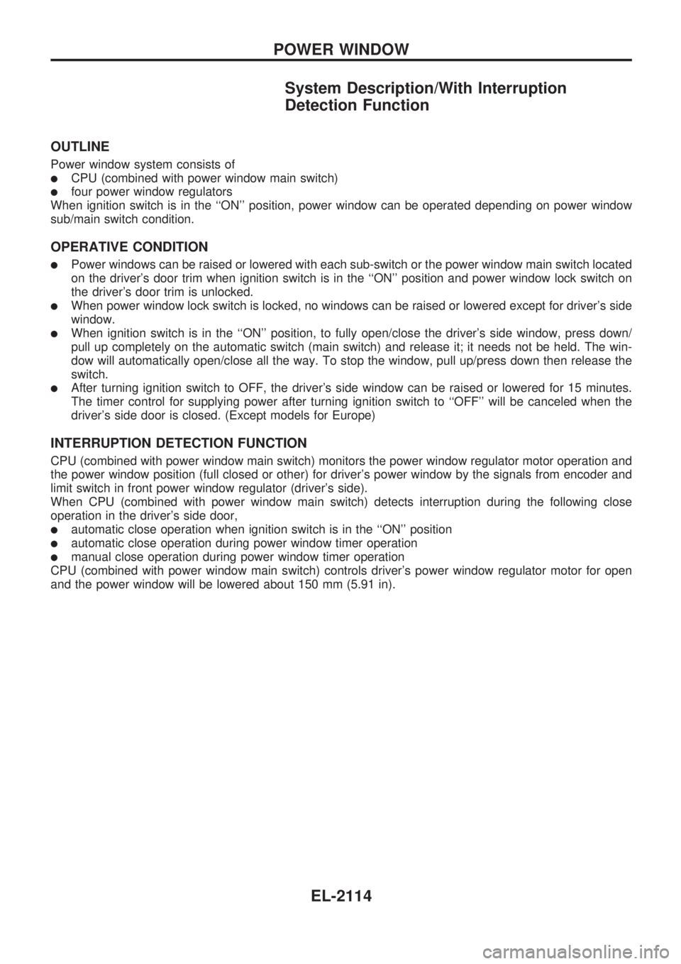
System Description/With Interruption
Detection Function
OUTLINE
Power window system consists of
lCPU (combined with power window main switch)
lfour power window regulators
When ignition switch is in the ``ON'' position, power window can be operated depending on power window
sub/main switch condition.
OPERATIVE CONDITION
lPower windows can be raised or lowered with each sub-switch or the power window main switch located
on the driver's door trim when ignition switch is in the ``ON'' position and power window lock switch on
the driver's door trim is unlocked.
lWhen power window lock switch is locked, no windows can be raised or lowered except for driver's side
window.
lWhen ignition switch is in the ``ON'' position, to fully open/close the driver's side window, press down/
pull up completely on the automatic switch (main switch) and release it; it needs not be held. The win-
dow will automatically open/close all the way. To stop the window, pull up/press down then release the
switch.
lAfter turning ignition switch to OFF, the driver's side window can be raised or lowered for 15 minutes.
The timer control for supplying power after turning ignition switch to ``OFF'' will be canceled when the
driver's side door is closed. (Except models for Europe)
INTERRUPTION DETECTION FUNCTION
CPU (combined with power window main switch) monitors the power window regulator motor operation and
the power window position (full closed or other) for driver's power window by the signals from encoder and
limit switch in front power window regulator (driver's side).
When CPU (combined with power window main switch) detects interruption during the following close
operation in the driver's side door,
lautomatic close operation when ignition switch is in the ``ON'' position
lautomatic close operation during power window timer operation
lmanual close operation during power window timer operation
CPU (combined with power window main switch) controls driver's power window regulator motor for open
and the power window will be lowered about 150 mm (5.91 in).
POWER WINDOW
EL-2114
Page 194 of 666
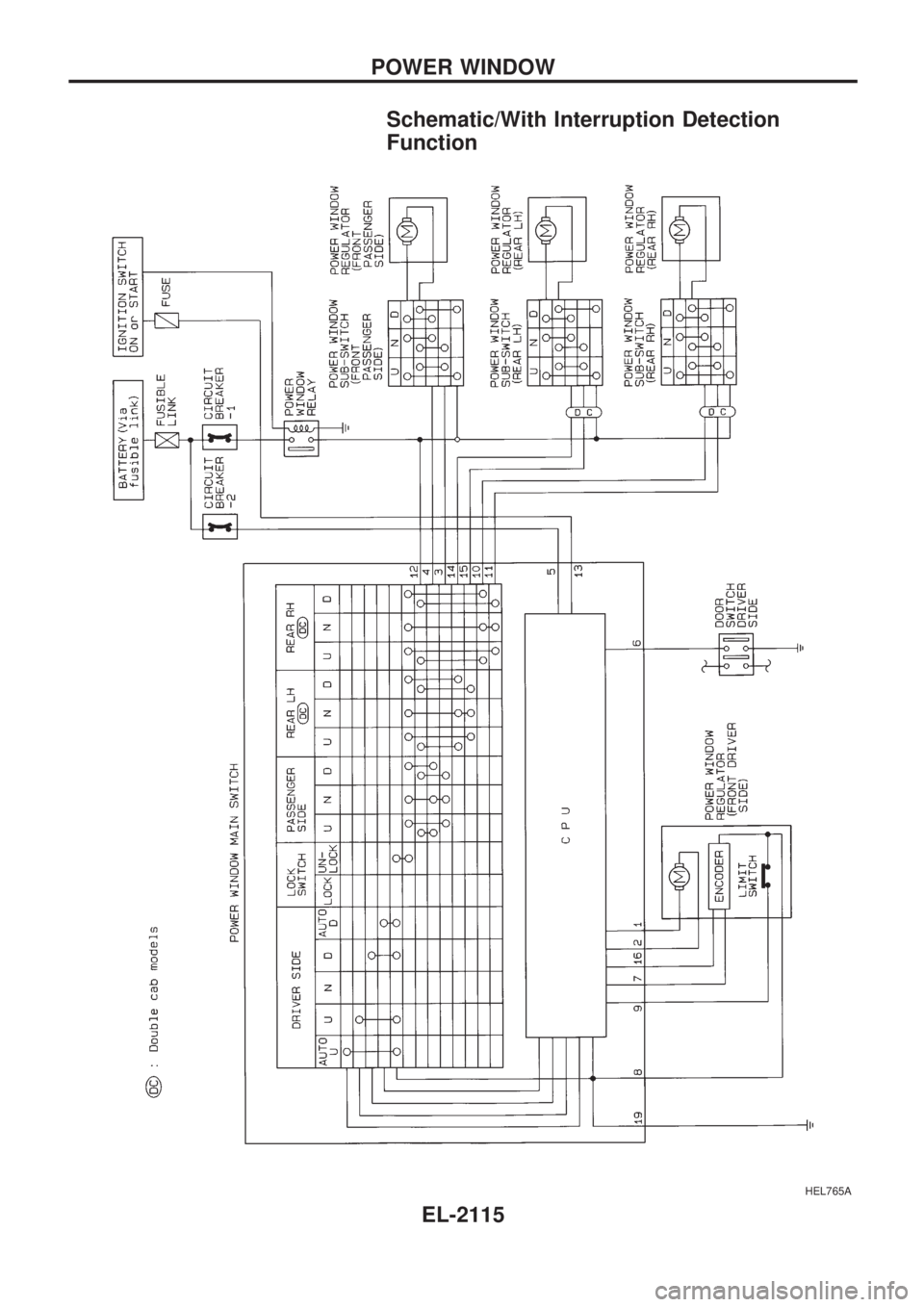
Schematic/With Interruption Detection
Function
HEL765A
POWER WINDOW
EL-2115
Page 195 of 666
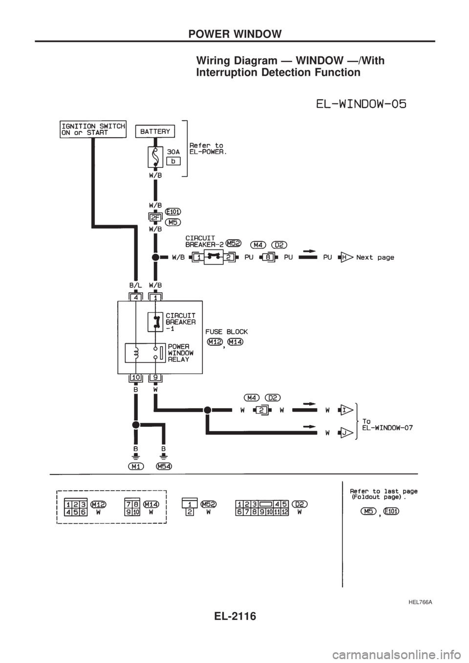
Wiring Diagram Ð WINDOW Ð/With
Interruption Detection Function
HEL766A
POWER WINDOW
EL-2116
Page 196 of 666
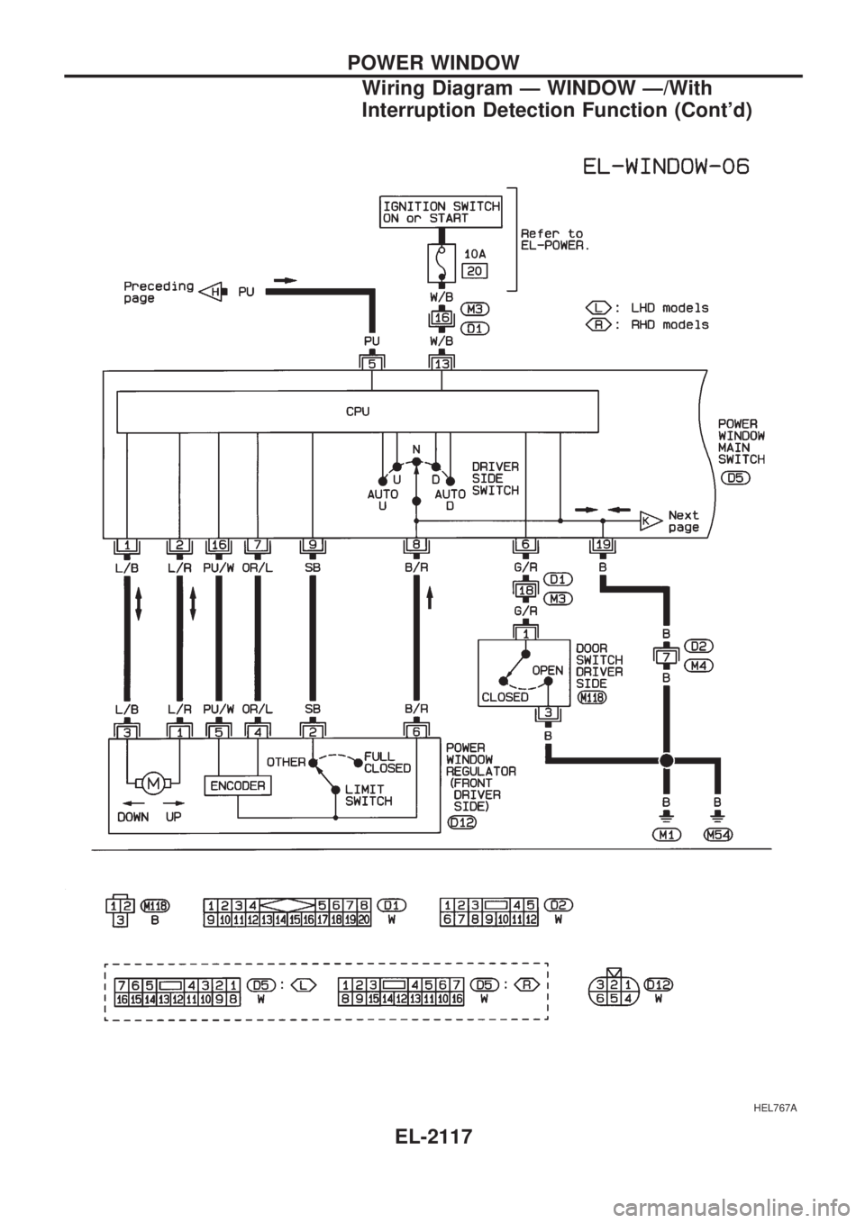
HEL767A
POWER WINDOW
Wiring Diagram Ð WINDOW Ð/With
Interruption Detection Function (Cont'd)
EL-2117
Page 197 of 666
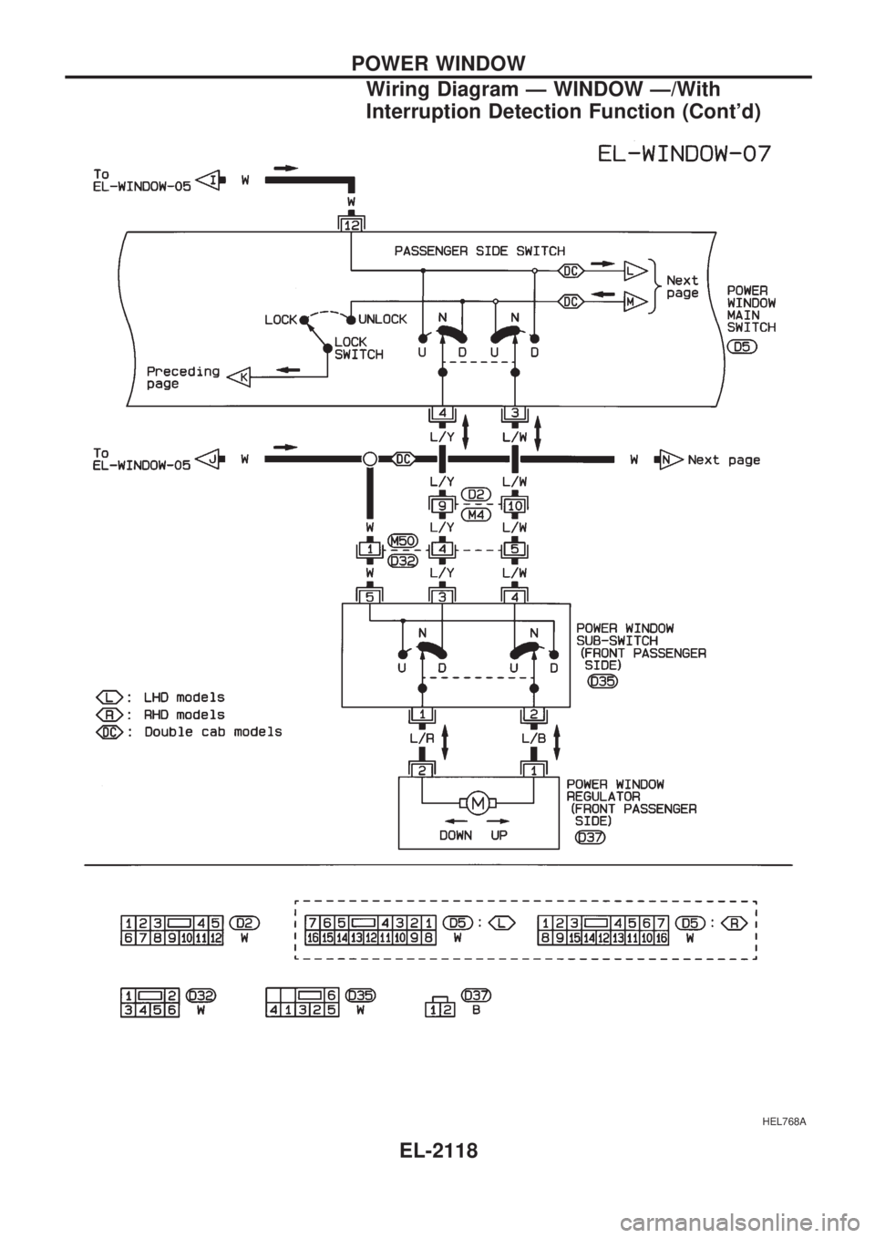
HEL768A
POWER WINDOW
Wiring Diagram Ð WINDOW Ð/With
Interruption Detection Function (Cont'd)
EL-2118
Page 198 of 666
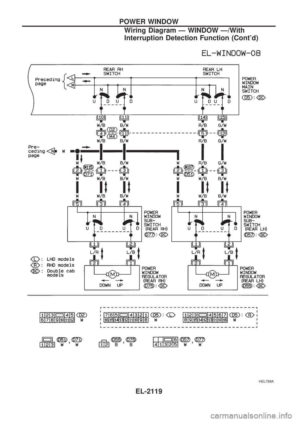
HEL769A
POWER WINDOW
Wiring Diagram Ð WINDOW Ð/With
Interruption Detection Function (Cont'd)
EL-2119
Page 199 of 666
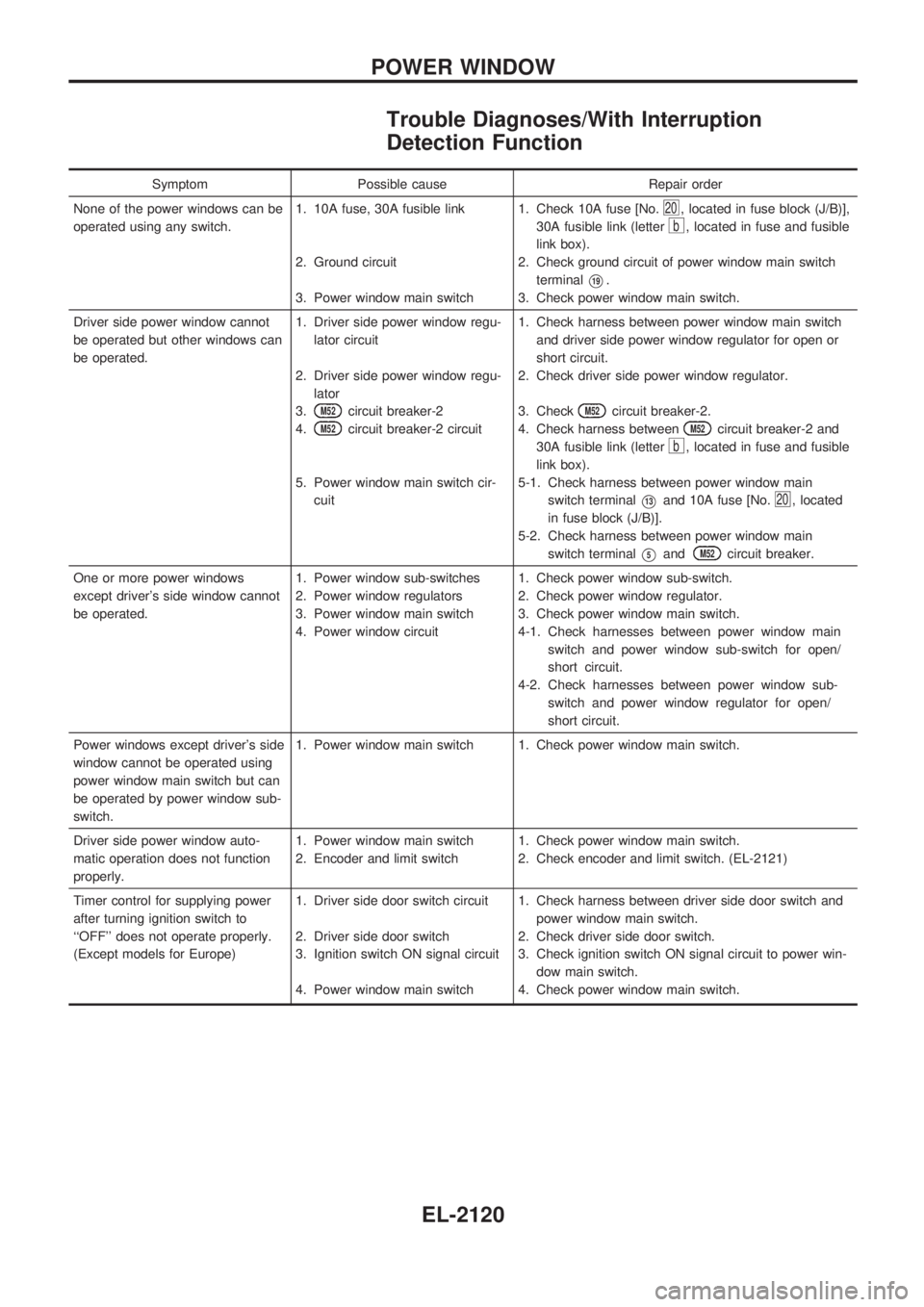
Trouble Diagnoses/With Interruption
Detection Function
Symptom Possible cause Repair order
None of the power windows can be
operated using any switch.1. 10A fuse, 30A fusible link
2. Ground circuit
3. Power window main switch1. Check 10A fuse [No.
20, located in fuse block (J/B)],
30A fusible link (letter
b, located in fuse and fusible
link box).
2. Check ground circuit of power window main switch
terminal
V19.
3. Check power window main switch.
Driver side power window cannot
be operated but other windows can
be operated.1. Driver side power window regu-
lator circuit
2. Driver side power window regu-
lator
3.
M52circuit breaker-2
4.
M52circuit breaker-2 circuit
5. Power window main switch cir-
cuit1. Check harness between power window main switch
and driver side power window regulator for open or
short circuit.
2. Check driver side power window regulator.
3. Check
M52circuit breaker-2.
4. Check harness between
M52circuit breaker-2 and
30A fusible link (letter
b, located in fuse and fusible
link box).
5-1. Check harness between power window main
switch terminal
V13and 10A fuse [No.20, located
in fuse block (J/B)].
5-2. Check harness between power window main
switch terminal
V5andM52circuit breaker.
One or more power windows
except driver's side window cannot
be operated.1. Power window sub-switches
2. Power window regulators
3. Power window main switch
4. Power window circuit1. Check power window sub-switch.
2. Check power window regulator.
3. Check power window main switch.
4-1. Check harnesses between power window main
switch and power window sub-switch for open/
short circuit.
4-2. Check harnesses between power window sub-
switch and power window regulator for open/
short circuit.
Power windows except driver's side
window cannot be operated using
power window main switch but can
be operated by power window sub-
switch.1. Power window main switch 1. Check power window main switch.
Driver side power window auto-
matic operation does not function
properly.1. Power window main switch
2. Encoder and limit switch1. Check power window main switch.
2. Check encoder and limit switch. (EL-2121)
Timer control for supplying power
after turning ignition switch to
``OFF'' does not operate properly.
(Except models for Europe)1. Driver side door switch circuit
2. Driver side door switch
3. Ignition switch ON signal circuit
4. Power window main switch1. Check harness between driver side door switch and
power window main switch.
2. Check driver side door switch.
3. Check ignition switch ON signal circuit to power win-
dow main switch.
4. Check power window main switch.
POWER WINDOW
EL-2120
Page 200 of 666
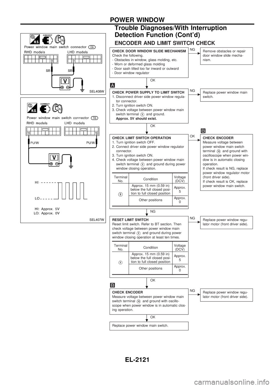
ENCODER AND LIMIT SWITCH CHECK
CHECK DOOR WINDOW SLIDE MECHANISM
Check the following.
- Obstacles in window, glass molding, etc.
- Worn or deformed glass molding
- Door sash tilted too far inward or outward
- Door window regulator
OK
cNG
Remove obstacles or repair
door window slide mecha-
nism.
CHECK POWER SUPPLY TO LIMIT SWITCH
1. Disconnect driver side power window regula-
tor connector.
2. Turn ignition switch ON.
3. Check voltage between power window main
switch terminal
V9and ground.
Approx. 5V should exist.
OK
cNG
Replace power window main
switch.
CHECK LIMIT SWITCH OPERATION
1. Turn ignition switch OFF.
2. Connect driver side power window regulator
connector.
3. Turn ignition switch ON.
4. Check voltage between power window main
switch terminal
V9and ground during power
window closing operation.
NG
cOK
CHECK ENCODER
Measure voltage between
power window main switch
terminal
V16and ground with
oscilloscope when power win-
dow is in automatic closing
operation.
If check result is NG, replace
power window regulator motor
(front driver side).
If check result is OK, replace
power window main switch.
RESET LIMIT SWITCH
Reset limit switch. Refer to BT section. Then
check voltage between power window main
switch terminal
V9and ground during power
window closing operation at least ten times.
OK
cNG
Replace power window regu-
lator motor (front driver side).
CHECK ENCODER
Measure voltage between power window main
switch terminal
V16and ground with oscillo-
scope when power window is in automatic clos-
ing operation.
OK
cNG
Replace power window regu-
lator motor (front driver side).
Replace power window main switch.
Terminal
No.ConditionVoltage
(DCV)
V9
Approx. 15 mm (0.59 in)
below the full closed posi-
tion to full closed positionApprox.
5
Other positionsApprox.
0
Terminal
No.ConditionVoltage
(DCV)
V9
Approx. 15 mm (0.59 in)
below the full closed posi-
tion to full closed positionApprox.
5
Other positionsApprox.
0
SEL408W
SEL407W
.
.
.
.
.
POWER WINDOW
Trouble Diagnoses/With Interruption
Detection Function (Cont'd)
EL-2121