NISSAN PICK-UP 1999 Owner's Guide
Manufacturer: NISSAN, Model Year: 1999, Model line: PICK-UP, Model: NISSAN PICK-UP 1999Pages: 666, PDF Size: 16.21 MB
Page 31 of 666
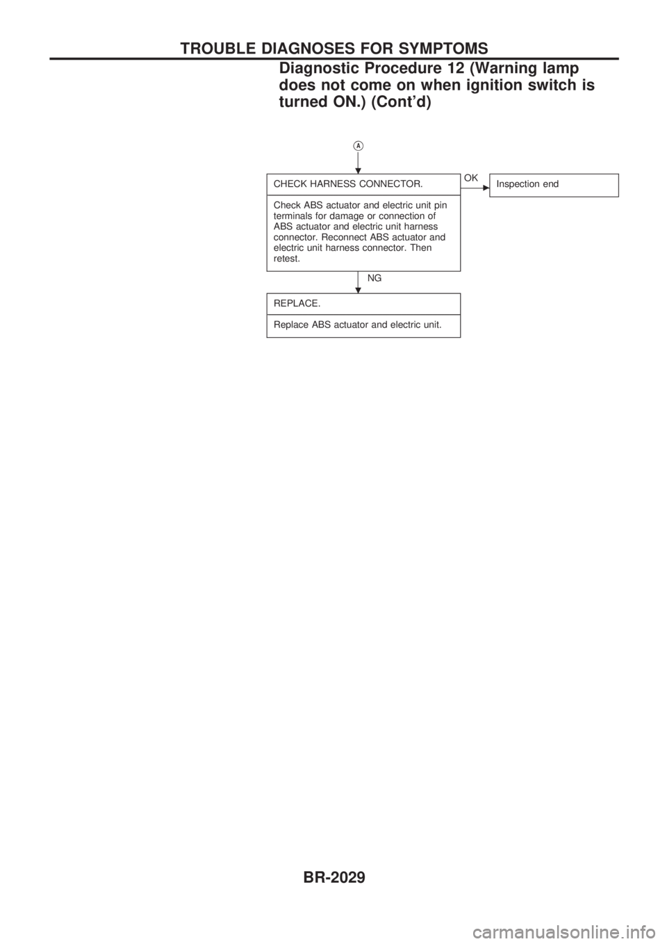
VA
CHECK HARNESS CONNECTOR.
-------------------------------------------------------------------------------------------------------------------------------------------------------------------------------------------------------------------------------------------------------------------------------------------------------------
Check ABS actuator and electric unit pin
terminals for damage or connection of
ABS actuator and electric unit harness
connector. Reconnect ABS actuator and
electric unit harness connector. Then
retest.
NG
cOK
Inspection end
REPLACE.
-------------------------------------------------------------------------------------------------------------------------------------------------------------------------------------------------------------------------------------------------------------------------------------------------------------
Replace ABS actuator and electric unit.
.
.
TROUBLE DIAGNOSES FOR SYMPTOMS
Diagnostic Procedure 12 (Warning lamp
does not come on when ignition switch is
turned ON.) (Cont'd)
BR-2029
Page 32 of 666
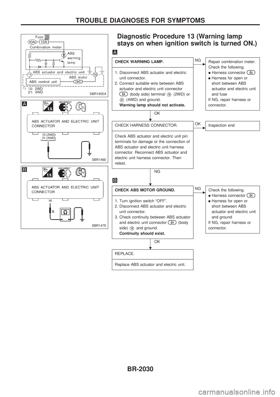
Diagnostic Procedure 13 (Warning lamp
stays on when ignition switch is turned ON.)
CHECK WARNING LAMP.
-------------------------------------------------------------------------------------------------------------------------------------------------------------------------------------------------------------------------------------------------------------------------------------------------------------
1. Disconnect ABS actuator and electric
unit connector.
2. Connect suitable wire between ABS
actuator and electric unit connector
E4(body side) terminalV10(2WD) or
V21(4WD) and ground.
Warning lamp should not activate.
OK
cNG
Repair combination meter.
Check the following.
lHarness connectorE4
lHarness for open or
short between ABS
actuator and electric unit
and fuse
If NG, repair harness or
connector.
CHECK HARNESS CONNECTOR.
-------------------------------------------------------------------------------------------------------------------------------------------------------------------------------------------------------------------------------------------------------------------------------------------------------------
Check ABS actuator and electric unit pin
terminals for damage or the connection of
ABS actuator and electric unit harness
connector. Reconnect ABS actuator and
electric unit harness connector. Then
retest.
NG
cOK
Inspection end
CHECK ABS MOTOR GROUND.
-------------------------------------------------------------------------------------------------------------------------------------------------------------------------------------------------------------------------------------------------------------------------------------------------------------
1. Turn ignition switch ªOFFº.
2. Disconnect ABS actuator and electric
unit connector.
3. Check continuity between ABS actuator
and electric unit connector
E4(body
side)
V16and ground.
Continuity should exist.
OK
cNG
Check the following.
lHarness connectorE4
lHarness for open or
short between ABS
actuator and electric unit
and ground
If NG, repair harness or
connector.
REPLACE.
-------------------------------------------------------------------------------------------------------------------------------------------------------------------------------------------------------------------------------------------------------------------------------------------------------------
Replace ABS actuator and electric unit.
SBR145EA
SBR146E
SBR147E
.
.
.
TROUBLE DIAGNOSES FOR SYMPTOMS
BR-2030
Page 33 of 666
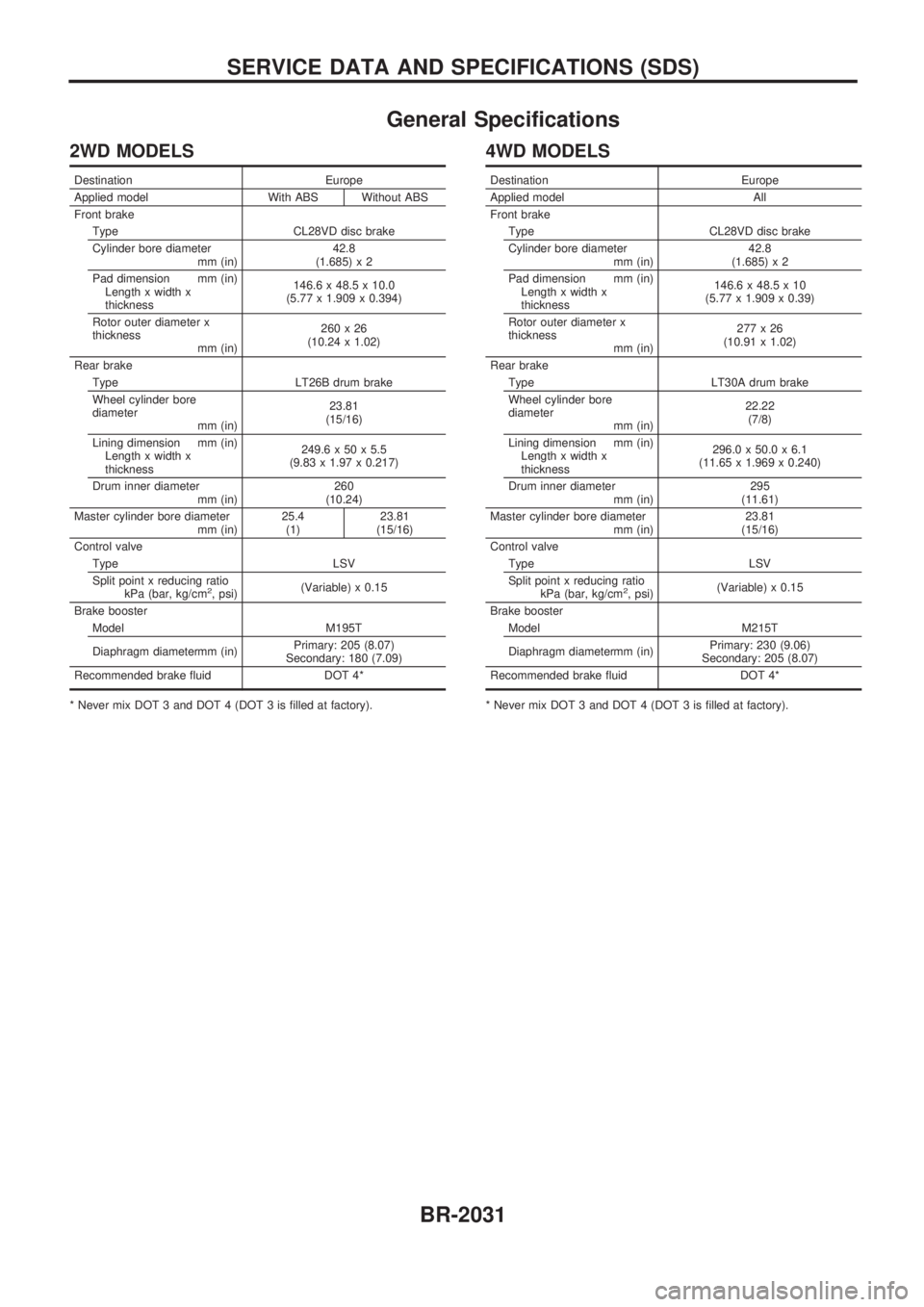
General Specifications
2WD MODELS
Destination Europe
Applied model With ABS Without ABS
Front brake
Type CL28VD disc brake
Cylinder bore diameter
mm (in)42.8
(1.685) x 2
Pad dimension mm (in)
Length x width x
thickness146.6 x 48.5 x 10.0
(5.77 x 1.909 x 0.394)
Rotor outer diameter x
thickness
mm (in)260x26
(10.24 x 1.02)
Rear brake
Type LT26B drum brake
Wheel cylinder bore
diameter
mm (in)23.81
(15/16)
Lining dimension mm (in)
Length x width x
thickness249.6 x 50 x 5.5
(9.83 x 1.97 x 0.217)
Drum inner diameter
mm (in)260
(10.24)
Master cylinder bore diameter
mm (in)25.4
(1)23.81
(15/16)
Control valve
Type LSV
Split point x reducing ratio
kPa (bar, kg/cm
2, psi)(Variable) x 0.15
Brake booster
Model M195T
Diaphragm diametermm (in)Primary: 205 (8.07)
Secondary: 180 (7.09)
Recommended brake fluid DOT 4*
* Never mix DOT 3 and DOT 4 (DOT 3 is filled at factory).
4WD MODELS
Destination Europe
Applied model All
Front brake
Type CL28VD disc brake
Cylinder bore diameter
mm (in)42.8
(1.685) x 2
Pad dimension mm (in)
Length x width x
thickness146.6 x 48.5 x 10
(5.77 x 1.909 x 0.39)
Rotor outer diameter x
thickness
mm (in)277x26
(10.91 x 1.02)
Rear brake
Type LT30A drum brake
Wheel cylinder bore
diameter
mm (in)22.22
(7/8)
Lining dimension mm (in)
Length x width x
thickness296.0 x 50.0 x 6.1
(11.65 x 1.969 x 0.240)
Drum inner diameter
mm (in)295
(11.61)
Master cylinder bore diameter
mm (in)23.81
(15/16)
Control valve
Type LSV
Split point x reducing ratio
kPa (bar, kg/cm
2, psi)(Variable) x 0.15
Brake booster
Model M215T
Diaphragm diametermm (in)Primary: 230 (9.06)
Secondary: 205 (8.07)
Recommended brake fluid DOT 4*
* Never mix DOT 3 and DOT 4 (DOT 3 is filled at factory).
SERVICE DATA AND SPECIFICATIONS (SDS)
BR-2031
Page 34 of 666
BODY&TRIM
SECTION
BT
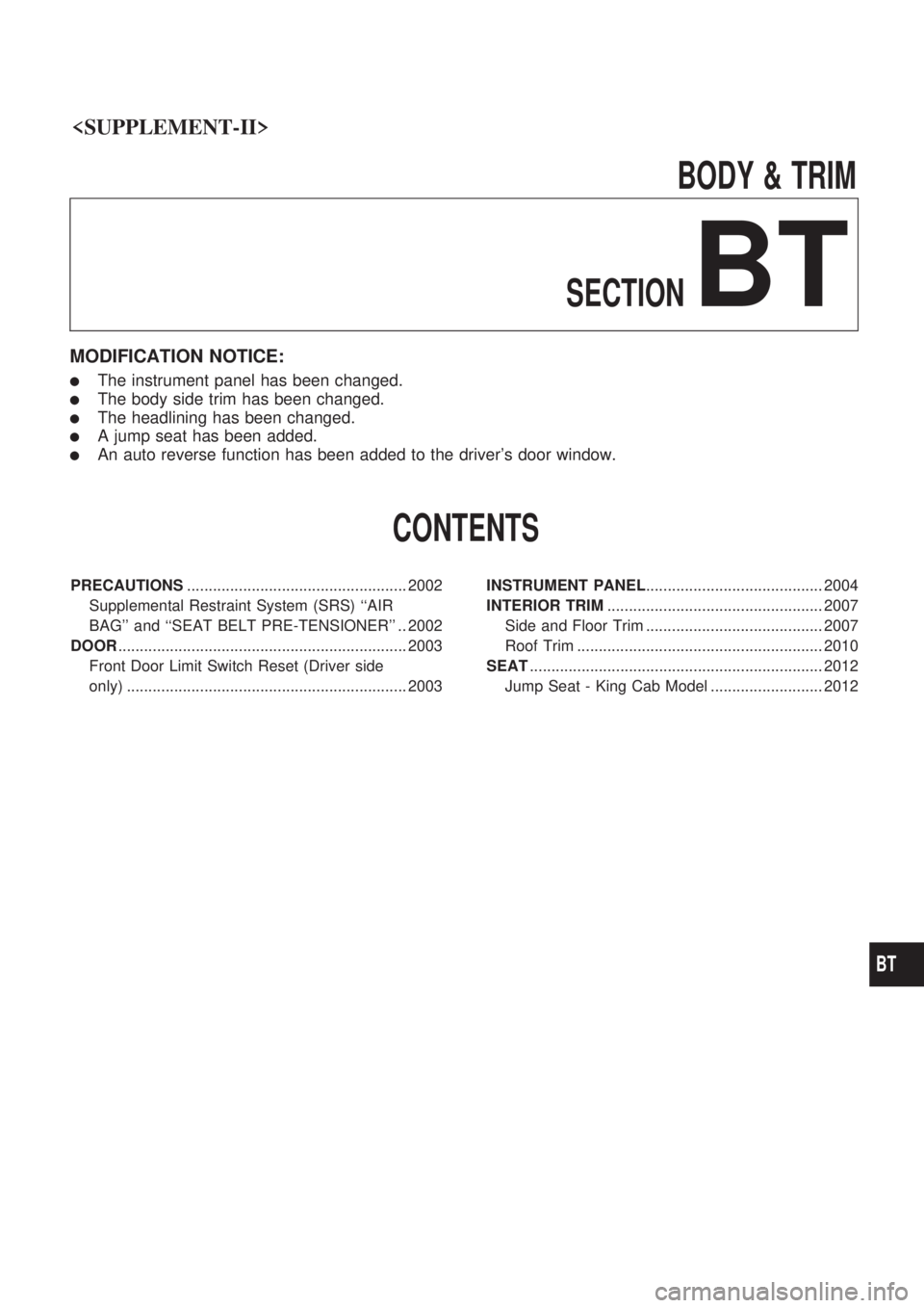
MODIFICATION NOTICE:
lThe instrument panel has been changed.
lThe body side trim has been changed.
lThe headlining has been changed.
lA jump seat has been added.
lAn auto reverse function has been added to the driver's door window.
CONTENTS
PRECAUTIONS ................................................... 2002
Supplemental Restraint System (SRS) ``AIR
BAG'' and ``SEAT BELT PRE-TENSIONER'' .. 2002
DOOR ................................................................... 2003
Front Door Limit Switch Reset (Driver side
only) ................................................................. 2003 INSTRUMENT PANEL
......................................... 2004
INTERIOR TRIM .................................................. 2007
Side and Floor Trim ......................................... 2007
Roof Trim ......................................................... 2010
SEAT .................................................................... 2012
Jump Seat - King Cab Model .......................... 2012
BT
Page 35 of 666
Supplemental Restraint System (SRS) ``AIR
BAG'' and ``SEAT BELT PRE-TENSIONER''
The Supplemental Restraint System such as ªAIR BAGº and ªSEAT BELT PRE-TENSIONERº used along
with a seat belt, helps to reduce the risk or severity of injury to the driver and front passenger in a frontal
collision. The SRS system composition which is available to NISSAN MODEL D22 is as follows (The com-
position varies according to the destination and optional equipment.):
Driver air bag module (located in the center of the steering wheel), front passenger air bag module (located
on the instrument panel on passenger side), seat belt pre-tensioner, a diagnosis sensor unit, warning lamp,
wiring harness and spiral cable.
Information necessary to service the system safely is included in theRS sectionof this Service Manual.
WARNING:
lTo avoid rendering the SRS inoperative, which could increase the risk of personal injury or death
in the event of a collision which would result in air bag inflation, all maintenance must be per-
formed by an authorized NISSAN dealer.
lImproper maintenance, including incorrect removal and installation of the SRS, can lead to per-
sonal injury caused by unintentional activation of the system. For removal of Spiral Cable and
Air Bag Module, see the RS section.
lDo not use electrical test equipment on any circuit related to the SRS unless instructed to in this
Service Manual. Spiral Cable and wiring harnesses (except ªSEAT BELT PRE-TENSIONERº) cov-
ered with yellow insulation either just before the harness connectors or for the complete harness
are related to the SRS.
PRECAUTIONS
BT-2002
Page 36 of 666
Front Door Limit Switch Reset (Driver side
only)
RESET CONDITIONS
After each of the following operations are performed, reset the
limit switch (with built-in motor).
lRegulator removal and installation
lRemoval of motor from regulator
lOperation of regulator as a single unit
lDoor glass removal and installation
lGlass run removal and installation
RESET PROCEDURES
After installing parts, proceed as follows:
1. Close the door window completely.
2. Press the reset switch and open the door window completely.
3. Release the reset switch. After making sure the reset switch
has returned to the original position, close the door window
completely.
4. The limit switch is now reset.
CAUTION:
Be sure to manually open or close the door window. (Do not
use the automatic open-close procedures.)
SBT845
DOOR
BT-2003
Page 37 of 666
CAUTION:
lDisconnect both terminals from battery in advance.
lDisconnect air bag module connector in advance.
lBe careful not to scratch finishers and other parts.
lNever tamper with or force air bag lid open, as this may adversely affect air bag performance.
REMOVAL Ð Instrument panel assembly
Instrument panel assemblyCombination meterAudio controlHeater and A/C control
Remove driver's air bag module and steering wheel.
Refer to ªSUPPLEMENTAL RESTRAINT SYSTEMº in RS
section for details.Tilt steering column down
fully
V1Steering column coverlRemove screws.
V2Instrument lower panel driver side.lRemove screws and bolts.
V3Cluster lid AlRemove screws.
V4Combination meterlRemove screws, then disconnect harness connectors.
V5Glove box assemblylRemove screws.lThen disconnect passenger air bag module connec-
tor.
lThen remove passenger air bag module bracket.
Refer to ªSUPPLEMENTAL RESTRAINT SYSTEMº
in RS section for details.
V6Remove ashtray.
V7Cluster lid ClRemove screws, then disconnect harness connectors.
V8Audio and deck pocketlRemove screws, then disconnect harness connectors.
V9Heater and A/C controllDisconnect temperature control cable and harness connectors.
V10Instrument stay cover lower centerlRemove screws.
V11Ventilator grille driver side
V12Defroster grille
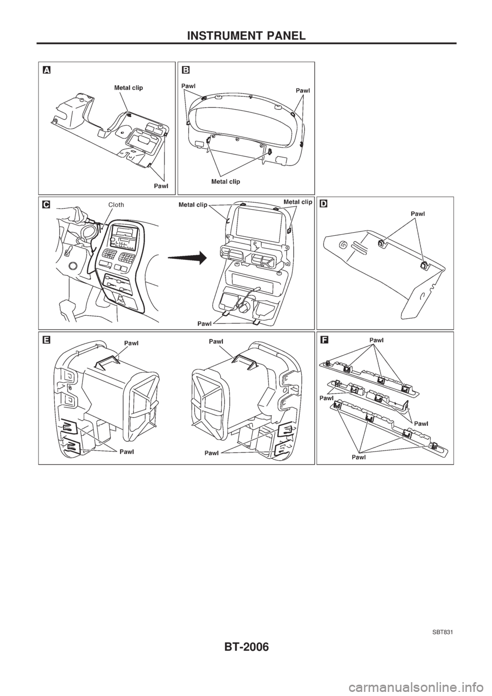
Remove front pillar garnish.
Refer to ªSide and Floor Trimº in ªINTERIOR TRIMº for
details, BT-2007.
V13Instrument panel assemblylRemove screws and bolts.
V14Air duct passenger sidelRemove screws.
V15Passenger air bag modulelRefer to ªSUPPLEMENTAL RESTRAINT SYSTEMº
in RS section for details.
INSTRUMENT PANEL
BT-2004
Page 38 of 666
SBT830
INSTRUMENT PANEL
BT-2005
Page 39 of 666
SBT831
INSTRUMENT PANEL
BT-2006
Page 40 of 666
Side and Floor Trim
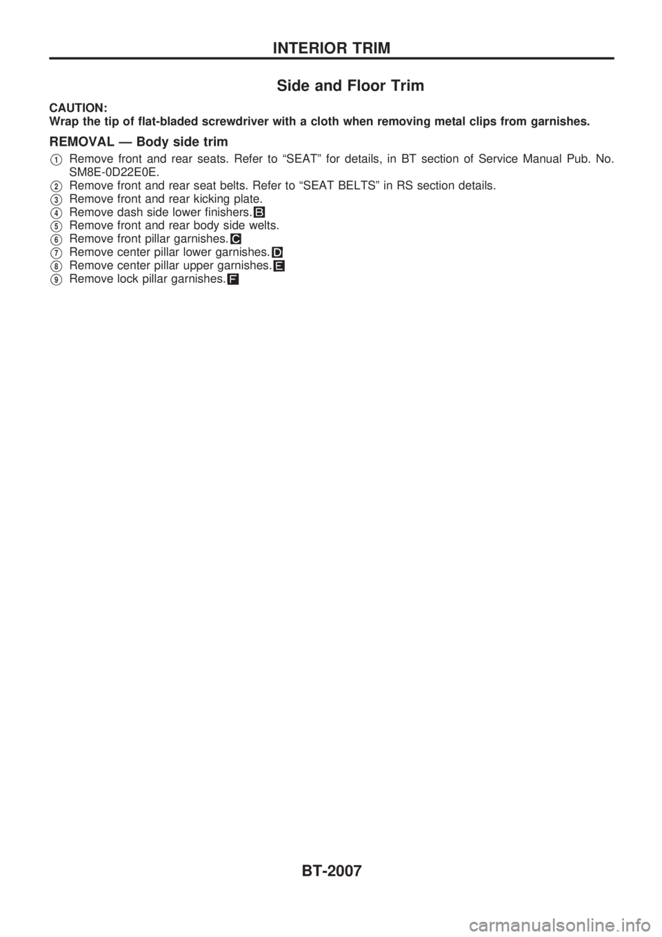
CAUTION:
Wrap the tip of flat-bladed screwdriver with a cloth when removing metal clips from garnishes.
REMOVAL Ð Body side trim
V1Remove front and rear seats. Refer to ªSEATº for details, in BT section of Service Manual Pub. No.
SM8E-0D22E0E.
V2Remove front and rear seat belts. Refer to ªSEAT BELTSº in RS section details.
V3Remove front and rear kicking plate.
V4Remove dash side lower finishers.
V5Remove front and rear body side welts.
V6Remove front pillar garnishes.
V7Remove center pillar lower garnishes.
V8Remove center pillar upper garnishes.
V9Remove lock pillar garnishes.
INTERIOR TRIM
BT-2007