NISSAN PICK-UP 1999 Service Manual
PICK-UP 1999
NISSAN
NISSAN
https://www.carmanualsonline.info/img/5/57373/w960_57373-0.png
NISSAN PICK-UP 1999 Service Manual
Trending: check engine, spare wheel, air suspension, air conditioning, fog light, power steering, fuses
Page 41 of 666
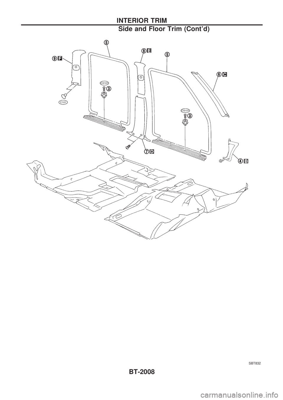
SBT832
INTERIOR TRIM
Side and Floor Trim (Cont'd)
BT-2008
Page 42 of 666
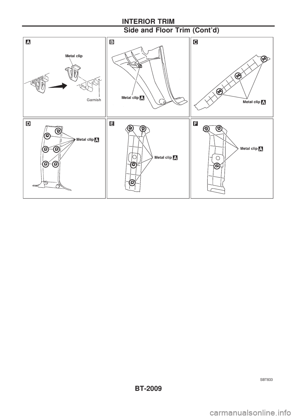
SBT833
INTERIOR TRIM
Side and Floor Trim (Cont'd)
BT-2009
Page 43 of 666
Roof Trim
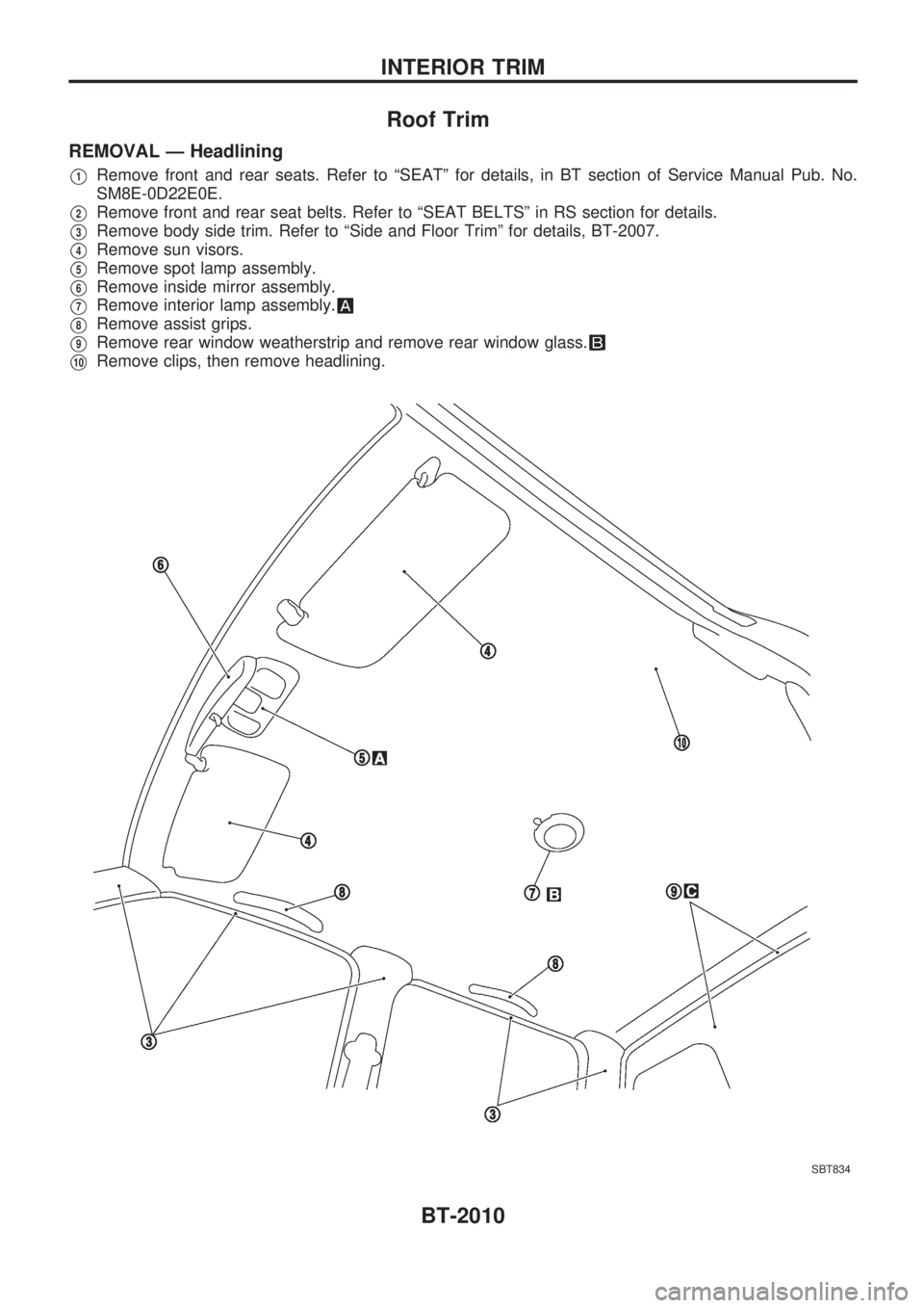
REMOVAL Ð Headlining
V1Remove front and rear seats. Refer to ªSEATº for details, in BT section of Service Manual Pub. No.
SM8E-0D22E0E.
V2Remove front and rear seat belts. Refer to ªSEAT BELTSº in RS section for details.
V3Remove body side trim. Refer to ªSide and Floor Trimº for details, BT-2007.
V4Remove sun visors.
V5Remove spot lamp assembly.
V6Remove inside mirror assembly.
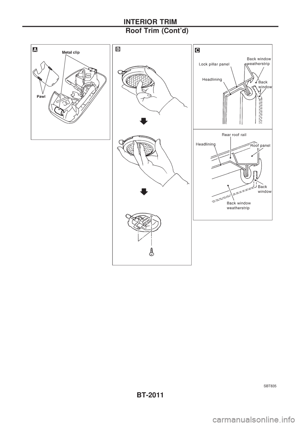
V7Remove interior lamp assembly.
V8Remove assist grips.
V9Remove rear window weatherstrip and remove rear window glass.
V10Remove clips, then remove headlining.
SBT834
INTERIOR TRIM
BT-2010
Page 44 of 666
SBT835
INTERIOR TRIM
Roof Trim (Cont'd)
BT-2011
Page 45 of 666
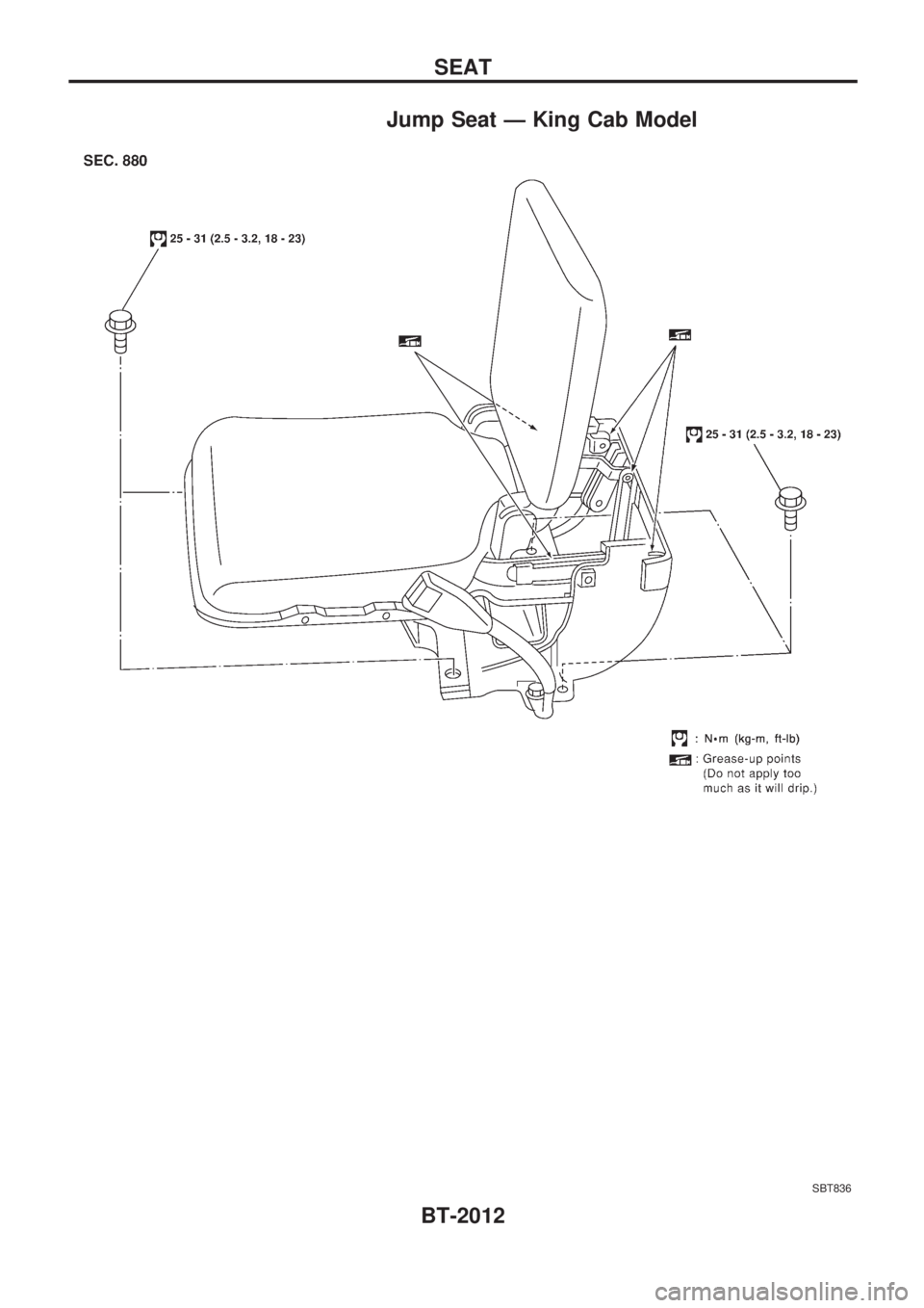
Jump Seat Ð King Cab Model
SBT836
SEAT
BT-2012
Page 46 of 666

ENGINECONTROLSYSTEM
SECTION
EC
MODIFICATION NOTICE:
Gasoline engine
Diesel engine
lWiring diagrams have been changed.
CONTENTS
PRECAUTIONS AND PREPARATION ............... 2003
Supplemental Restraint System (SRS) ``AIR
BAG'' and ``SEAT BELT PRE-TENSIONER'' .. 2003
KA24E
ENGINE AND EMISSION CONTROL OVERALL
SYSTEM............................................................... 2004
Circuit Diagram ................................................ 2004
TROUBLE DIAGNOSIS FOR POWER
SUPPLY ............................................................... 2005
Main Power Supply and Ground Circuit .......... 2005
TROUBLE DIAGNOSIS FOR ``CAMSHAFT
POSI SEN'' (DTC 11) ........................................... 2007
Camshaft Position Sensor (CMPS) ................. 2007
TROUBLE DIAGNOSIS FOR ``MASS AIR FLOW
SEN'' (DTC 12) .................................................... 2008
Mass Air Flow Sensor (MAFS) ........................ 2008
TROUBLE DIAGNOSIS FOR
NON-DETECTABLE ITEMS ................................ 2009
Vehicle Speed Sensor (VSS) .......................... 2009
Heated Oxygen Sensor (HO2S)
- LHD Models - ................................................ 2010
Idle Air Control Valve (IACV) - Auxiliary Air
Control (AAC) Valve ........................................ 2011 Park/Neutral Position Switch ........................... 2012
EVAP Canister Purge Control Solenoid
Valve ................................................................ 2013
Start Signal ...................................................... 2014
Fuel Pump........................................................ 2015
Power Steering Oil Pressure Switch ............... 2016
Swirl Control Valve Control Solenoid Valve .... 2017
IACV-FICD Solenoid Valve .............................. 2018
MIL & Data Link Connectors ........................... 2019
TD
QUICK-GLOW SYSTEM ...................................... 2020
Circuit Diagram ................................................ 2020
Wiring Diagram ................................................ 2021
EGR SYSTEM ...................................................... 2027
Wiring Diagram ................................................ 2027
SOLENOID TIMER .............................................. 2031
Wiring Diagram ................................................ 2031
FUEL HEATER SYSTEM .................................... 2033
Wiring Diagram ................................................ 2033
FAST IDLE CONTROL CIRCUIT ........................ 2034
Wiring Diagram ................................................ 2034
EC
Page 47 of 666
When you read wiring diagrams:
lRead GI section, ªHOW TO READ WIRING DIAGRAMSº.
lSee EL section, ªPOWER SUPPLY ROUTINGº for power distribution circuit.
When you perform trouble diagnoses, read GI section, ªHOW TO FOLLOW FLOW CHART IN
TROUBLE DIAGNOSESº and ªHOW TO PERFORM EFFICIENT DIAGNOSIS FOR AN ELECTRICAL
INCIDENTº.
EC-2002
Page 48 of 666
Supplemental Restraint System (SRS) ªAIR
BAGº and ªSEAT BELT PRE-TENSIONERº
The Supplemental Restraint System such as ªAIR BAGº and ªSEAT BELT PRE-TENSIONERº used along
with a seat belt, helps to reduce the risk or severity of injury to the driver and front passenger in a frontal
collision. The SRS system composition which is available to NISSAN MODEL D22 is as follows (The com-
position varies according to the destination and optional equipment.):
Driver air bag module (located in the center of the steering wheel), front passenger air bag module (located
on the instrument panel on passenger side), seat belt pre-tensioner, a diagnosis sensor unit, warning lamp,
wiring harness and spiral cable.
Information necessary to service the system safely is included in theRS sectionof this Service Manual.
WARNING:
lTo avoid rendering the SRS inoperative, which could increase the risk of personal injury or death
in the event of a collision which would result in air bag inflation, all maintenance must be per-
formed by an authorized NISSAN dealer.
lImproper maintenance, including incorrect removal and installation of the SRS, can lead to per-
sonal injury caused by unintentional activation of the system. For removal of Spiral Cable and
Air Bag Module, see the RS section.
lDo not use electrical test equipment on any circuit related to the SRS unless instructed to in this
Service Manual. Spiral Cable and wiring harnesses (except ªSEAT BELT PRE-TENSIONERº) cov-
ered with yellow insulation either just before the harness connectors or for the complete harness
are related to the SRS.
PRECAUTIONS AND PREPARATION
EC-2003
Page 49 of 666
Circuit Diagram
HEC631
ENGINE AND EMISSION CONTROL OVERALL SYSTEMKA24E
EC-2004
Page 50 of 666
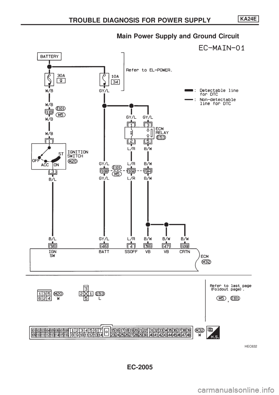
Main Power Supply and Ground Circuit
HEC632
TROUBLE DIAGNOSIS FOR POWER SUPPLYKA24E
EC-2005
Trending: clock setting, oil viscosity, window, belt, hood release, sensor, engine coolant
