NISSAN PRIMERA 1999 Electronic Repair Manual
Manufacturer: NISSAN, Model Year: 1999, Model line: PRIMERA, Model: NISSAN PRIMERA 1999Pages: 2267, PDF Size: 35.74 MB
Page 1831 of 2267
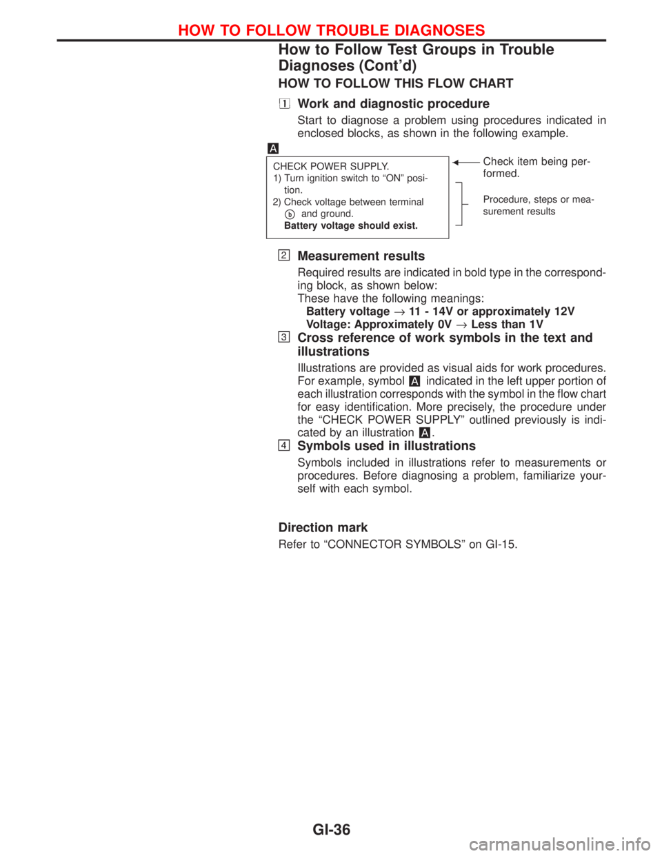
HOW TO FOLLOW THIS FLOW CHART
Work and diagnostic procedure
Start to diagnose a problem using procedures indicated in
enclosed blocks, as shown in the following example.
CHECK POWER SUPPLY.
1) Turn ignition switch to ªONº posi-
tion.
2) Check voltage between terminal
pband ground.
Battery voltage should exist.
FCheck item being per-
formed.
Procedure, steps or mea-
surement results
Measurement results
Required results are indicated in bold type in the correspond-
ing block, as shown below:
These have the following meanings:
Battery voltage®11 - 14V or approximately 12V
Voltage: Approximately 0V®Less than 1V
Cross reference of work symbols in the text and
illustrations
Illustrations are provided as visual aids for work procedures.
For example, symbol
indicated in the left upper portion of
each illustration corresponds with the symbol in the flow chart
for easy identification. More precisely, the procedure under
the ªCHECK POWER SUPPLYº outlined previously is indi-
cated by an illustration
.
Symbols used in illustrations
Symbols included in illustrations refer to measurements or
procedures. Before diagnosing a problem, familiarize your-
self with each symbol.
Direction mark
Refer to ªCONNECTOR SYMBOLSº on GI-15.
HOW TO FOLLOW TROUBLE DIAGNOSES
How to Follow Test Groups in Trouble
Diagnoses (Cont'd)
GI-36
Page 1832 of 2267
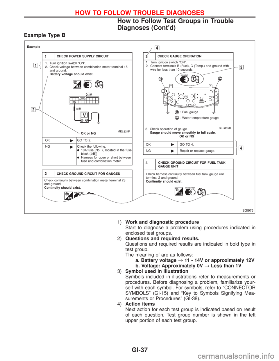
Example Type B
1)Work and diagnostic procedure
Start to diagnose a problem using procedures indicated in
enclosed test groups.
2)Questions and required results.
Questions and required results are indicated in bold type in
test group.
The meaning of are as follows:
a. Battery voltage®11 - 14V or approximately 12V
b. Voltage: Approximately 0V®Less than 1V
3)Symbol used in illustration
Symbols included in illustrations refer to measurements or
procedures. Before diagnosing a problem, familiarize your-
self with each symbol. For symbols, refer to ªCONNECTOR
SYMBOLSº (GI-15) and ªKey to Symbols Signifying Mea-
surements or Proceduresº (GI-38).
4)Action items
Next action for each test group is indicated based on result
of each question. Test group number is shown in the left
upper portion of each test group.
SGI975
Example
CHECK POWER SUPPLY CIRCUIT
1. Turn ignition switch ªONº.
2. Check voltage between combination meter terminal 15
and ground.
Battery voltage should exist.
OK or NG
OK
NGGO TO 2.
Check the following.
l10A fuse [No. 7, located in the fuse
block (J/B)]
lHarness for open or short between
fuse and combination meter
CHECK GROUND CIRCUIT FOR GAUGES
Check continuity between combination meter terminal 23
and ground.
Continuity should exist.CHECK GAUGE OPERATION
1. Turn ignition switch ªONº.
2. Connect terminals B (Fuel), C (Temp.) and ground with
wire for less than 10 seconds.
Fuel gauge
Water temperature gauge
3. Check operation of gauge.
Gauge should move smoothly to full scale.
OK or NG
OK
NGGO TO 4.
Repair or replace gauge.
CHECK GROUND CIRCUIT FOR FUEL TANK
GAUGE UNIT
Check harness continuity between fuel tank gauge unit
terminal 2 and ground.
Continuity should exist.
HOW TO FOLLOW TROUBLE DIAGNOSES
How to Follow Test Groups in Trouble
Diagnoses (Cont'd)
GI-37
Page 1833 of 2267
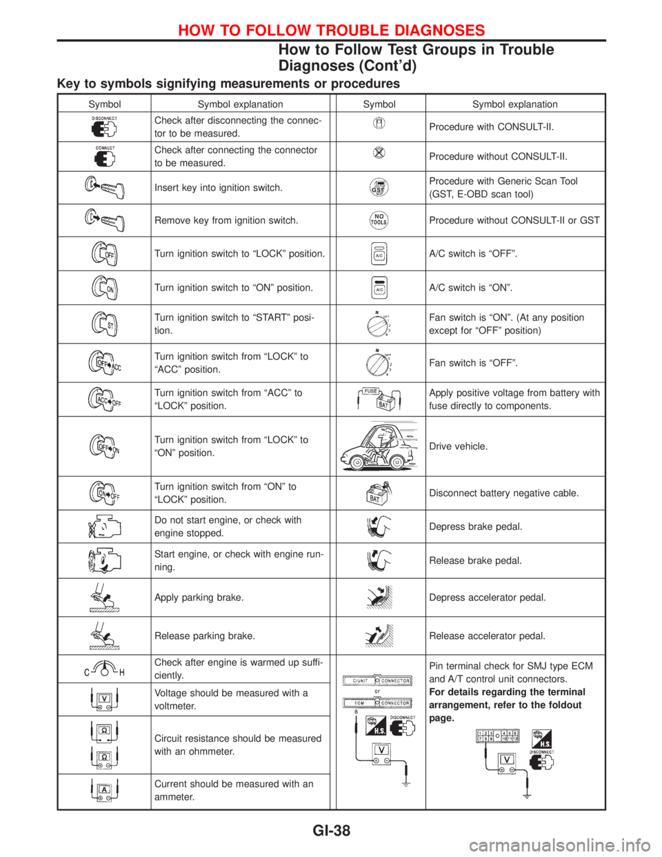
Key to symbols signifying measurements or procedures
Symbol Symbol explanation Symbol Symbol explanation
Check after disconnecting the connec-
tor to be measured.Procedure with CONSULT-II.
Check after connecting the connector
to be measured.Procedure without CONSULT-II.
Insert key into ignition switch.Procedure with Generic Scan Tool
(GST, E-OBD scan tool)
Remove key from ignition switch.Procedure without CONSULT-II or GST
Turn ignition switch to ªLOCKº position.A/C switch is ªOFFº.
Turn ignition switch to ªONº position.A/C switch is ªONº.
Turn ignition switch to ªSTARTº posi-
tion.Fan switch is ªONº. (At any position
except for ªOFFº position)
Turn ignition switch from ªLOCKº to
ªACCº position.Fan switch is ªOFFº.
Turn ignition switch from ªACCº to
ªLOCKº position.Apply positive voltage from battery with
fuse directly to components.
Turn ignition switch from ªLOCKº to
ªONº position.Drive vehicle.
Turn ignition switch from ªONº to
ªLOCKº position.Disconnect battery negative cable.
Do not start engine, or check with
engine stopped.Depress brake pedal.
Start engine, or check with engine run-
ning.Release brake pedal.
Apply parking brake.Depress accelerator pedal.
Release parking brake.Release accelerator pedal.
Check after engine is warmed up suffi-
ciently.Pin terminal check for SMJ type ECM
and A/T control unit connectors.
For details regarding the terminal
arrangement, refer to the foldout
page.
Voltage should be measured with a
voltmeter.
Circuit resistance should be measured
with an ohmmeter.
Current should be measured with an
ammeter.
HOW TO FOLLOW TROUBLE DIAGNOSES
How to Follow Test Groups in Trouble
Diagnoses (Cont'd)
GI-38
Page 1834 of 2267
Function and System Application
Diagnostic
test modeFunction ENGINE H×CVT ABSAIR
BAGNATS
Work supportThis mode enables a technician to adjust some devices faster
and more accurate by following the indications on CONSULT-II.´ÐÐÐÐ
Self-diagnostic
resultsSelf-diagnostic results can be read and erased quickly.´xx´´
Trouble diagnostic
recordCurrent self-diagnostic results and all trouble diagnostic records
previously stored can be read.ÐÐÐxÐ
ECU discriminated
No.Classification number of a replacement ECU can be read to pre-
vent an incorrect ECU from being installed.ÐÐдÐ
Data monitor Input/Output data in the ECM can be read.´xxÐÐ
DTC work supportThis mode enables a technician to set operating conditions to
confirm self-diagnosis status/results.x x ÐÐÐ
Active testDiagnostic Test Mode in which CONSULT-II drives some actua-
tors apart from the ECMs and also shifts some parameters in a
specified range.´ÐxÐÐ
ECM part number ECM part number can be read.´xxÐÐ
Control unit initialisa-
tionAll registered ignition key IDs in NATS components can be initia-
lised and new IDs can be registered.ÐÐÐÐ x
DTC & SRT confirma-
tionThe results of SRT (System Readiness Test) and the self-diag-
nosis status/results can be confirmed.x ÐÐÐÐ
´: Applicable
*1: NATS: Nissan Anti-Theft System
Nickel Metal Hydride Battery Replacement
CONSULT-II contains a nickel metal hydride battery. When replacing the battery obey the following:
WARNING:
Replace the nickel metal hydride battery with genuine CONSULT-II battery only. Use of another bat-
tery may present a risk of fire or explosion. The battery may present a fire or chemical burn hazard
if mistreated. Do not recharge, disassemble of dispose of in fire.
Keep the battery out of reach of children and discard used battery conforming to the local regula-
tions.
Checking Equipment
When ordering the equipment below, contact your NISSAN distributor.
Tool name Description
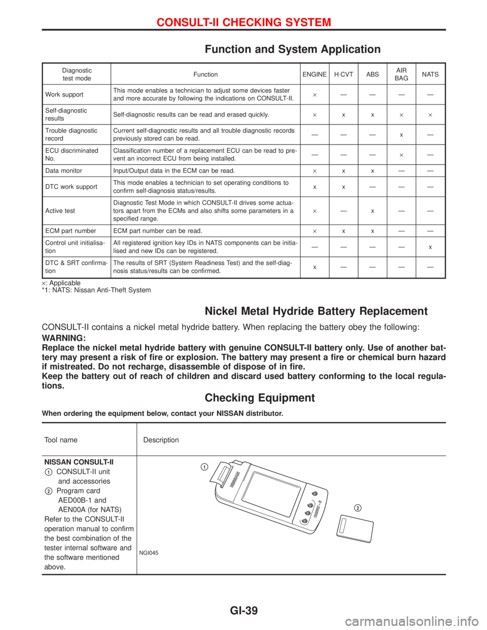
NISSAN CONSULT-II
p1CONSULT-II unit
and accessories
p2Program card
AED00B-1 and
AEN00A (for NATS)
Refer to the CONSULT-II
operation manual to confirm
the best combination of the
tester internal software and
the software mentioned
above.
NGI045
p1
p2
CONSULT-II CHECKING SYSTEM
GI-39
Page 1835 of 2267
NOTE:
lThe CONSULT-II must be used in conjunction with a program card.
CONSULT-II does not require loading (Initialisation) procedure.
lBe sure the CONSULT-II is turned off before installing or removing a program card.
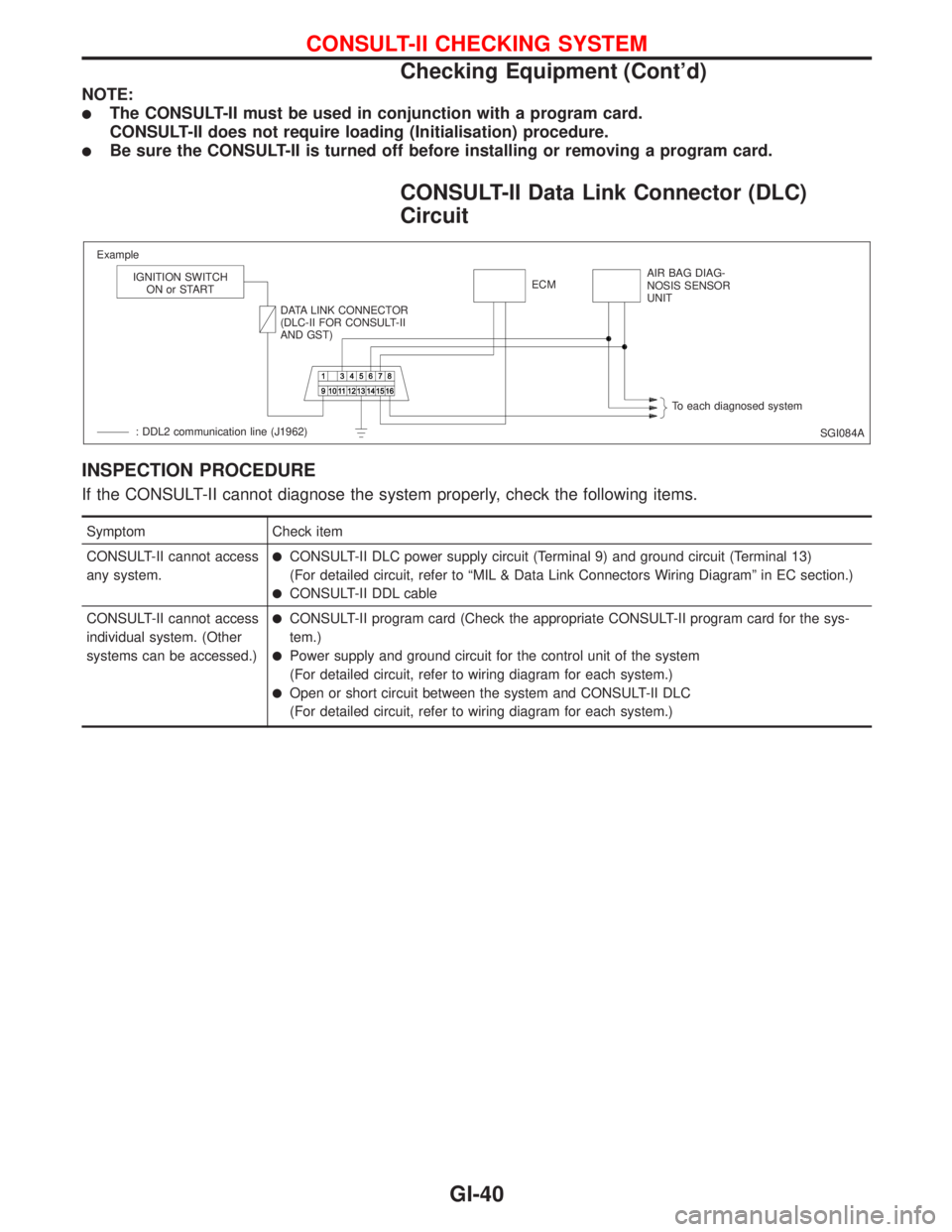
CONSULT-II Data Link Connector (DLC)
Circuit
INSPECTION PROCEDURE
If the CONSULT-II cannot diagnose the system properly, check the following items.
Symptom Check item
CONSULT-II cannot access
any system.
lCONSULT-II DLC power supply circuit (Terminal 9) and ground circuit (Terminal 13)
(For detailed circuit, refer to ªMIL & Data Link Connectors Wiring Diagramº in EC section.)
lCONSULT-II DDL cable
CONSULT-II cannot access
individual system. (Other
systems can be accessed.)
lCONSULT-II program card (Check the appropriate CONSULT-II program card for the sys-
tem.)
lPower supply and ground circuit for the control unit of the system
(For detailed circuit, refer to wiring diagram for each system.)
lOpen or short circuit between the system and CONSULT-II DLC
(For detailed circuit, refer to wiring diagram for each system.)
SGI084A Example
IGNITION SWITCH
ON or START
DATA LINK CONNECTOR
(DLC-II FOR CONSULT-II
AND GST)ECMAIR BAG DIAG-
NOSIS SENSOR
UNIT
To each diagnosed system
: DDL2 communication line (J1962)
CONSULT-II CHECKING SYSTEM
Checking Equipment (Cont'd)
GI-40
Page 1836 of 2267
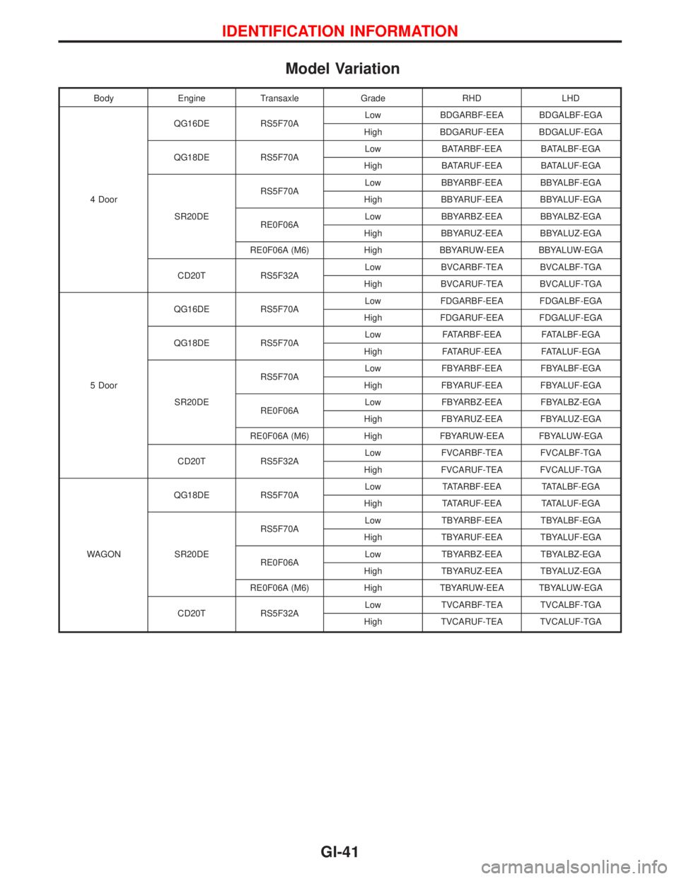
Model Variation
Body Engine Transaxle Grade RHD LHD
4 DoorQG16DE RS5F70ALow BDGARBF-EEA BDGALBF-EGA
High BDGARUF-EEA BDGALUF-EGA
QG18DE RS5F70ALow BATARBF-EEA BATALBF-EGA
High BATARUF-EEA BATALUF-EGA
SR20DERS5F70ALow BBYARBF-EEA BBYALBF-EGA
High BBYARUF-EEA BBYALUF-EGA
RE0F06ALow BBYARBZ-EEA BBYALBZ-EGA
High BBYARUZ-EEA BBYALUZ-EGA
RE0F06A (M6) High BBYARUW-EEA BBYALUW-EGA
CD20T RS5F32ALow BVCARBF-TEA BVCALBF-TGA
High BVCARUF-TEA BVCALUF-TGA
5 DoorQG16DE RS5F70ALow FDGARBF-EEA FDGALBF-EGA
High FDGARUF-EEA FDGALUF-EGA
QG18DE RS5F70ALow FATARBF-EEA FATALBF-EGA
High FATARUF-EEA FATALUF-EGA
SR20DERS5F70ALow FBYARBF-EEA FBYALBF-EGA
High FBYARUF-EEA FBYALUF-EGA
RE0F06ALow FBYARBZ-EEA FBYALBZ-EGA
High FBYARUZ-EEA FBYALUZ-EGA
RE0F06A (M6) High FBYARUW-EEA FBYALUW-EGA
CD20T RS5F32ALow FVCARBF-TEA FVCALBF-TGA
High FVCARUF-TEA FVCALUF-TGA
WAGONQG18DE RS5F70ALow TATARBF-EEATATALBF-EGA
HighTATARUF-EEATATALUF-EGA
SR20DERS5F70ALow TBYARBF-EEA TBYALBF-EGA
High TBYARUF-EEA TBYALUF-EGA
RE0F06ALow TBYARBZ-EEA TBYALBZ-EGA
High TBYARUZ-EEA TBYALUZ-EGA
RE0F06A (M6) High TBYARUW-EEA TBYALUW-EGA
CD20T RS5F32ALow TVCARBF-TEA TVCALBF-TGA
High TVCARUF-TEA TVCALUF-TGA
IDENTIFICATION INFORMATION
GI-41
Page 1837 of 2267
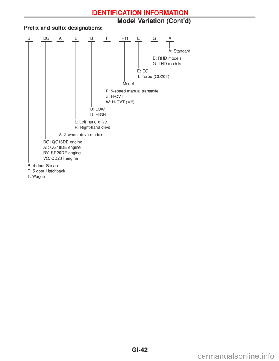
Prefix and suffix designations:
BDGALBFP11EGA
A: Standard
E: RHD models
G: LHD models
E: EGI
T: Turbo (CD20T)
Model
F: 5-speed manual transaxle
Z: H-CVT
W: H-CVT (M6)
B: LOW
U: HIGH
L: Left-hand drive
R: Right-hand drive
A: 2-wheel drive models
DG: QG16DE engine
AT: QG18DE engine
BY: SR20DE engine
VC: CD20T engine
B: 4-door Sedan
F: 5-door Hatchback
T: Wagon
IDENTIFICATION INFORMATION
Model Variation (Cont'd)
GI-42
Page 1838 of 2267
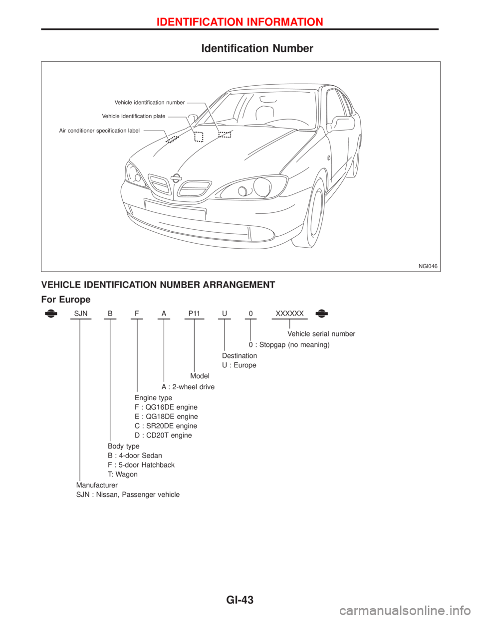
Identification Number
VEHICLE IDENTIFICATION NUMBER ARRANGEMENT
For Europe
SJNBFAP11U0XXXXXX
Vehicle serial number
0 : Stopgap (no meaning)
Destination
U : Europe
Model
A : 2-wheel drive
Engine type
F : QG16DE engine
E : QG18DE engine
C : SR20DE engine
D : CD20T engine
Body type
B : 4-door Sedan
F : 5-door Hatchback
T: Wagon
Manufacturer
SJN : Nissan, Passenger vehicle
NGI046 Vehicle identification plateVehicle identification number
Air conditioner specification label
IDENTIFICATION INFORMATION
GI-43
Page 1839 of 2267
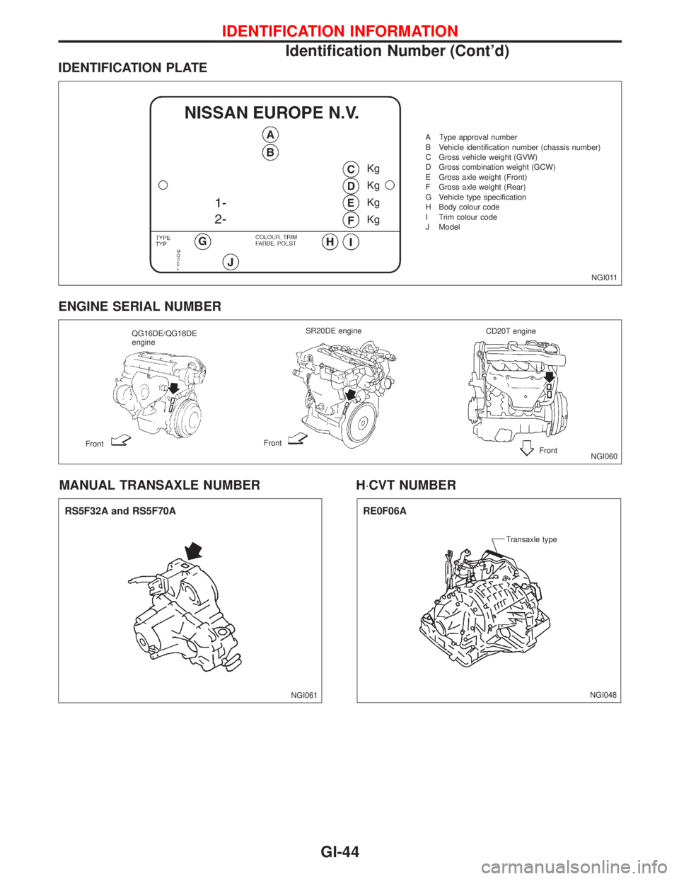
IDENTIFICATION PLATE
ENGINE SERIAL NUMBER
MANUAL TRANSAXLE NUMBER H×CVT NUMBER
NGI011 A Type approval number
B Vehicle identification number (chassis number)
C Gross vehicle weight (GVW)
D Gross combination weight (GCW)
E Gross axle weight (Front)
F Gross axle weight (Rear)
G Vehicle type specification
H Body colour code
I Trim colour code
J Model
NGI060 QG16DE/QG18DE
engineSR20DE engine
CD20T engine
FrontFront
Front
NGI061
RS5F32A and RS5F70A
NGI048 Transaxle type
RE0F06A
IDENTIFICATION INFORMATION
Identification Number (Cont'd)
GI-44
Page 1840 of 2267
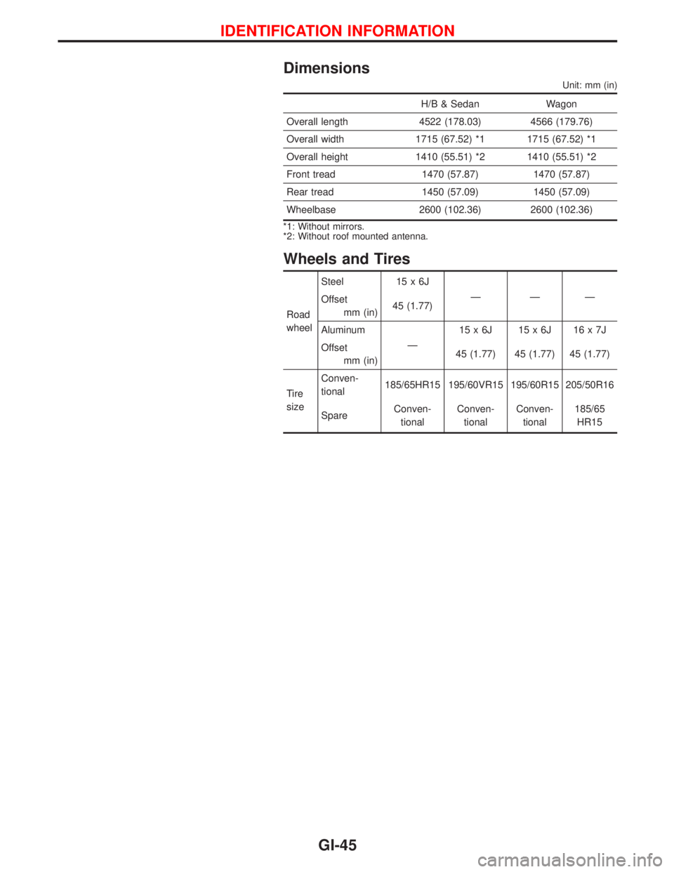
Dimensions
Unit: mm (in)
H/B & Sedan Wagon
Overall length 4522 (178.03) 4566 (179.76)
Overall width 1715 (67.52) *1 1715 (67.52) *1
Overall height 1410 (55.51) *2 1410 (55.51) *2
Front tread 1470 (57.87) 1470 (57.87)
Rear tread 1450 (57.09) 1450 (57.09)
Wheelbase 2600 (102.36) 2600 (102.36)
*1: Without mirrors.
*2: Without roof mounted antenna.
Wheels and Tires
Road
wheelSteel 15 x 6J
ÐÐÐ
Offset
mm (in)45 (1.77)
Aluminum
Ð15x6J 15x6J 16x7J
Offset
mm (in)45 (1.77) 45 (1.77) 45 (1.77)
Tire
sizeConven-
tional185/65HR15 195/60VR15 195/60R15 205/50R16
SpareConven-
tionalConven-
tionalConven-
tional185/65
HR15
IDENTIFICATION INFORMATION
GI-45