NISSAN PRIMERA 1999 Electronic Repair Manual
Manufacturer: NISSAN, Model Year: 1999, Model line: PRIMERA, Model: NISSAN PRIMERA 1999Pages: 2267, PDF Size: 35.74 MB
Page 1811 of 2267
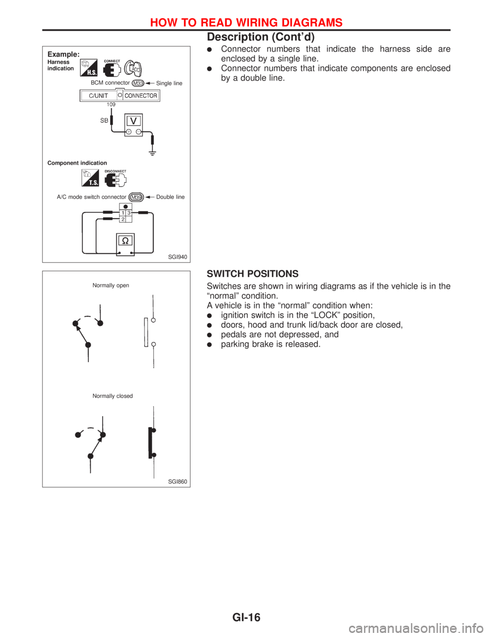
lConnector numbers that indicate the harness side are
enclosed by a single line.
lConnector numbers that indicate components are enclosed
by a double line.
SWITCH POSITIONS
Switches are shown in wiring diagrams as if the vehicle is in the
ªnormalº condition.
A vehicle is in the ªnormalº condition when:
lignition switch is in the ªLOCKº position,
ldoors, hood and trunk lid/back door are closed,
lpedals are not depressed, and
lparking brake is released.
SGI940
Example:Harness
indication
Single line BCM connector
Component indication
A/C mode switch connector Double line
SGI860 Normally open
Normally closed
HOW TO READ WIRING DIAGRAMS
Description (Cont'd)
GI-16
Page 1812 of 2267
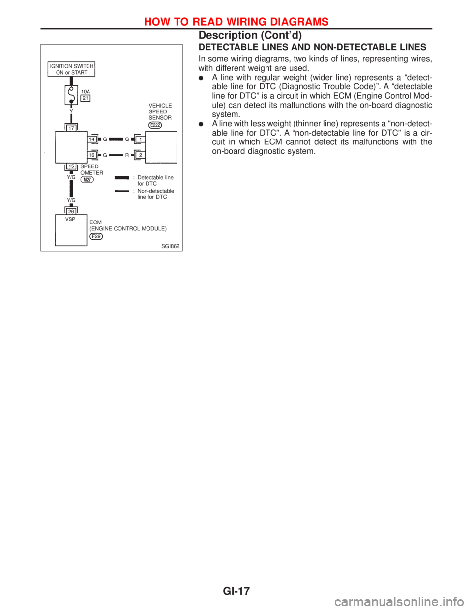
DETECTABLE LINES AND NON-DETECTABLE LINES
In some wiring diagrams, two kinds of lines, representing wires,
with different weight are used.
lA line with regular weight (wider line) represents a ªdetect-
able line for DTC (Diagnostic Trouble Code)º. A ªdetectable
line for DTCº is a circuit in which ECM (Engine Control Mod-
ule) can detect its malfunctions with the on-board diagnostic
system.
lA line with less weight (thinner line) represents a ªnon-detect-
able line for DTCº. A ªnon-detectable line for DTCº is a cir-
cuit in which ECM cannot detect its malfunctions with the
on-board diagnostic system.
SGI862
IGNITION SWITCH
ON or START
VEHICLE
SPEED
SENSOR
SPEED
OMETER
M27Detectable line
for DTC
Non-detectable
line for DTC
ECM
(ENGINE CONTROL MODULE)
HOW TO READ WIRING DIAGRAMS
Description (Cont'd)
GI-17
Page 1813 of 2267
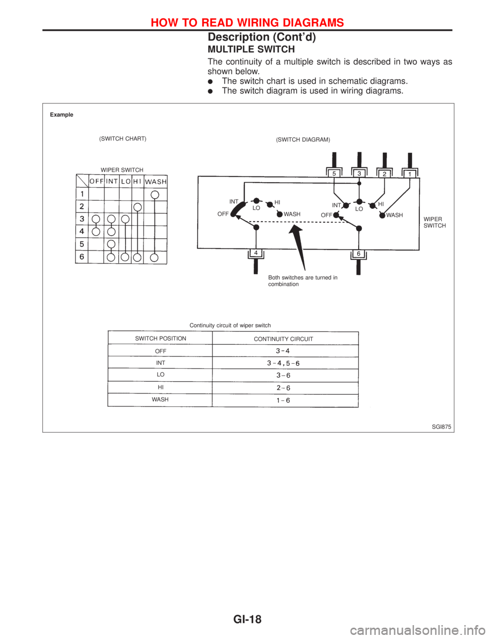
MULTIPLE SWITCH
The continuity of a multiple switch is described in two ways as
shown below.
lThe switch chart is used in schematic diagrams.
lThe switch diagram is used in wiring diagrams.
SGI875 Example
(SWITCH CHART)
WIPER SWITCH(SWITCH DIAGRAM)
INT
OFFLOHI
WASH
OFFINT
LOHI
WASH
WIPER
SWITCH
Both switches are turned in
combination
Continuity circuit of wiper switch
SWITCH POSITION
OFF
INT
LO
HI
WASHCONTINUITY CIRCUIT
HOW TO READ WIRING DIAGRAMS
Description (Cont'd)
GI-18
Page 1814 of 2267
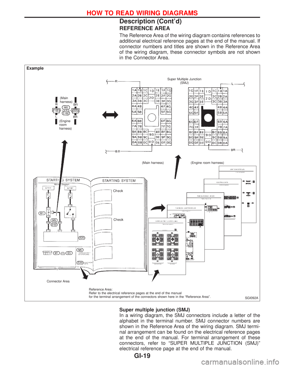
REFERENCE AREA
The Reference Area of the wiring diagram contains references to
additional electrical reference pages at the end of the manual. If
connector numbers and titles are shown in the Reference Area
of the wiring diagram, these connector symbols are not shown
in the Connector Area.
Super multiple junction (SMJ)
In a wiring diagram, the SMJ connectors include a letter of the
alphabet in the terminal number. SMJ connector numbers are
shown in the Reference Area of the wiring diagram. SMJ termi-
nal arrangement can be found on the electrical reference pages
at the end of the manual. For terminal arrangement of these
connectors, refer to ªSUPER MULTIPLE JUNCTION (SMJ)º
electrical reference page at the end of the manual.
SGI092A
Example
(Main
harness)
(Engine
room
harness)Super Multiple Junction
(SMJ)
(Main harness) (Engine room harness)
Connector Area
Reference Area:
Refer to the electrical reference pages at the end of the manual
for the terminal arrangement of the connectors shown here in the ªReference Areaº.
HOW TO READ WIRING DIAGRAMS
Description (Cont'd)
GI-19
Page 1815 of 2267
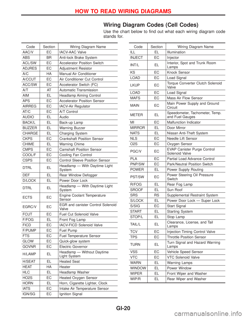
Wiring Diagram Codes (Cell Codes)
Use the chart below to find out what each wiring diagram code
stands for.
Code Section Wiring Diagram Name
AAC/V EC IACV-AAC Valve
ABS BR Anti-lock Brake System
ACL/SW EC Accelerator Position Switch
ADJRES EC Adjustment Resistor
A/C HA Manual Air Conditioner
A/CCUT EC Air Conditioner Cut Control
ACC/SW EC Accelerator Switch (FC)
A/T AT Automatic Transmission
AIM EL Headlamp Aiming Control
APS EC Accelerator Position Sensor
AIRREG EC IACV-Air Regulator
AT/C EC A/T Control
AUDIO EL Audio
BACK/L EL Back-up Lamp
BUZZER EL Warning Buzzer
CHARGE EL Charging System
CKPS EC Crankshaft Position Sensor
CHIME EL Warning Chime
CMPS EC Camshaft Position Sensor
COOL/F EC Cooling Fan Control
CSPS EC Control Sleeve Position Sensor
DTRL ELHeadlamp Ð With Daytime Light
System
DEF EL Rear Window Defogger
D/LOCK EL Power Door Lock
DTRL ELHeadlamp Ð With Daytime Light
System
ECTS ECEngine Coolant Temperature
Sensor
EGRC/V ECEGR and canister Control Solenoid
Valve
FCUT EC Fuel Cut Solenoid Valve
F/FOG EL Front Fog Lamp
FICD EC IACV-FICD Solenoid Valve
F/PUMP EC Fuel Pump
FTS EC Fuel Temperature Sensor
GLOW EC Quick-glow system
GOVNR EC Electric Governor
H/LAMP ELHeadlamp Ð Without Daytime
Light System
H/SEAT EL Heated Seat
HEAT HA Heater
HLC EL Headlamp Washer
HO2S EC Heated Oxygen Sensor
HORN EL Horn, Cigarette Lighter, Clock
IATS EC Intake Air Temperature Sensor
IGN/SG EC Ignition SignalCode Section Wiring Diagram Name
ILL EL Illumination
INJECT EC Injector
INT/L ELInterior, Spot and Trunk Room
Lamps
KS EC Knock Sensor
LOAD EC Load Signal
LKUP ECTorque Converter Clutch Solenoid
Valve
LOAD EC Load Signal
MAFS EC Mass Air Flow Sensor
MAIN ECMain Power Supply and Ground
Circuit
METER ELSpeedometer, Tachometer, Temp.
and Fuel Gauges
MI EC Malfunction Indicator
MIRROR EL Door Mirror
NATS EL Nissan Anti-Theft System
NLS EC Needle Lift Sensor
O2S EC Oxygen Sensor
PGC/V ECEVAP Canister Purge Control
Solenoid Valve
PLA EC Partial Load Advance Control
PNP/SW EC Park/Neutral Position Switch
POWER EL Power Supply Routing
PST/SW ECPower Steering Oil Pressure
Switch
R/FOG EL Rear Fog Lamp
SROOF EL Sun Roof
SRS RS Supplemental Restraint System
S/LOCK EL Power Door Lock Ð Super Lock
S/SIG EC Start Signal
START EL Starting System
STOP/L EL Stop Lamp
TAIL/L ELClearance, License, and Tail
Lamps
TCV EC Injection Timing Control Valve
TPS EC Throttle Position Sensor
TURN ELTurn Signal and Hazard Warning
Lamps
VSS EC Vehicle Speed Sensor
VTC EC VTC Solenoid Valve
WARN EL Warning Lamps
WINDOW EL Power Window
WIPER EL Front Wiper and Washer
WIP/R EL Rear Wiper and Washer
HOW TO READ WIRING DIAGRAMS
GI-20
Page 1816 of 2267
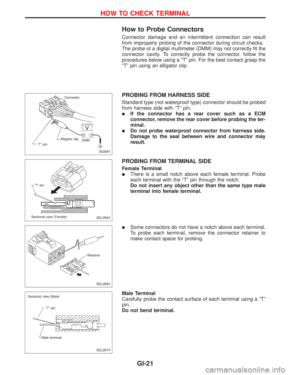
How to Probe Connectors
Connector damage and an intermittent connection can result
from improperly probing of the connector during circuit checks.
The probe of a digital multimeter (DMM) may not correctly fit the
connector cavity. To correctly probe the connector, follow the
procedures below using a ªTº pin. For the best contact grasp the
ªTº pin using an alligator clip.
PROBING FROM HARNESS SIDE
Standard type (not waterproof type) connector should be probed
from harness side with ªTº pin.
lIf the connector has a rear cover such as a ECM
connector, remove the rear cover before probing the ter-
minal.
lDo not probe waterproof connector from harness side.
Damage to the seal between wire and connector may
result.
PROBING FROM TERMINAL SIDE
Female Terminal
lThere is a small notch above each female terminal. Probe
each terminal with the ªTº pin through the notch.
Do not insert any object other than the same type male
terminal into female terminal.
lSome connectors do not have a notch above each terminal.
To probe each terminal, remove the connector retainer to
make contact space for probing.
Male Terminal
Carefully probe the contact surface of each terminal using a ªTº
pin.
Do not bend terminal.
SGI841 Connector
ªTº pinAlligator clip
DMM
SEL265V ªTº pin
Sectional view (Female)
SEL266V Retainer
SEL267V Sectional view (Male)
ªTº pin
Male terminal
HOW TO CHECK TERMINAL
GI-21
Page 1817 of 2267
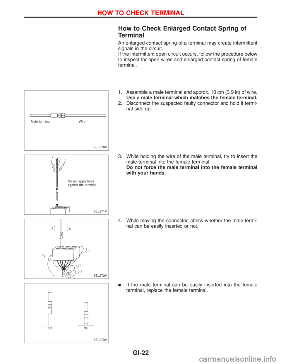
How to Check Enlarged Contact Spring of
Terminal
An enlarged contact spring of a terminal may create intermittent
signals in the circuit.
If the intermittent open circuit occurs, follow the procedure below
to inspect for open wires and enlarged contact spring of female
terminal.
1. Assemble a male terminal and approx. 10 cm (3.9 in) of wire.
Use a male terminal which matches the female terminal.
2. Disconnect the suspected faulty connector and hold it termi-
nal side up.
3. While holding the wire of the male terminal, try to insert the
male terminal into the female terminal.
Do not force the male terminal into the female terminal
with your hands.
4. While moving the connector, check whether the male termi-
nal can be easily inserted or not.
lIf the male terminal can be easily inserted into the female
terminal, replace the female terminal.
SEL270V Male terminal Wire
SEL271V Do not apply force
against the terminal.
SEL272V
SEL273V OKNG
HOW TO CHECK TERMINAL
GI-22
Page 1818 of 2267
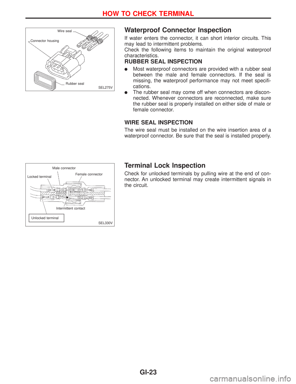
Waterproof Connector Inspection
If water enters the connector, it can short interior circuits. This
may lead to intermittent problems.
Check the following items to maintain the original waterproof
characteristics.
RUBBER SEAL INSPECTION
lMost waterproof connectors are provided with a rubber seal
between the male and female connectors. If the seal is
missing, the waterproof performance may not meet specifi-
cations.
lThe rubber seal may come off when connectors are discon-
nected. Whenever connectors are reconnected, make sure
the rubber seal is properly installed on either side of male or
female connector.
WIRE SEAL INSPECTION
The wire seal must be installed on the wire insertion area of a
waterproof connector. Be sure that the seal is installed properly.
Terminal Lock Inspection
Check for unlocked terminals by pulling wire at the end of con-
nector. An unlocked terminal may create intermittent signals in
the circuit.
SEL275V Wire seal
Connector housing
Rubber seal
SEL330V Locked terminal
Unlocked terminalIntermittent contact Male connector
Female connector
HOW TO CHECK TERMINAL
GI-23
Page 1819 of 2267
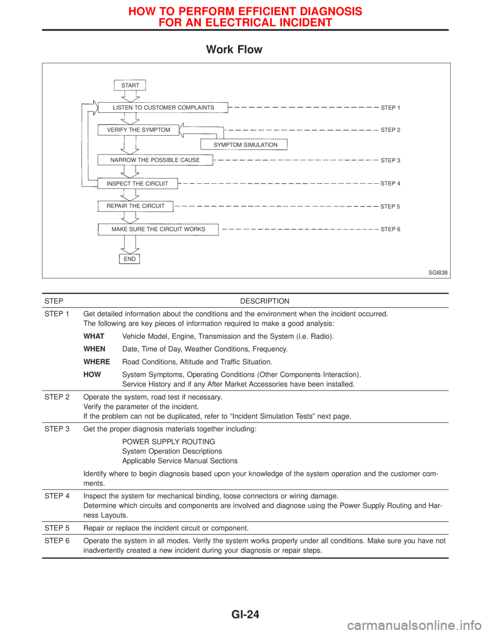
Work Flow
STEP DESCRIPTION
STEP 1 Get detailed information about the conditions and the environment when the incident occurred.
The following are key pieces of information required to make a good analysis:
WHATVehicle Model, Engine, Transmission and the System (i.e. Radio).
WHENDate, Time of Day, Weather Conditions, Frequency.
WHERERoad Conditions, Altitude and Traffic Situation.
HOWSystem Symptoms, Operating Conditions (Other Components Interaction).
Service History and if any After Market Accessories have been installed.
STEP 2 Operate the system, road test if necessary.
Verify the parameter of the incident.
If the problem can not be duplicated, refer to ªIncident Simulation Testsº next page.
STEP 3 Get the proper diagnosis materials together including:
POWER SUPPLY ROUTING
System Operation Descriptions
Applicable Service Manual Sections
Identify where to begin diagnosis based upon your knowledge of the system operation and the customer com-
ments.
STEP 4 Inspect the system for mechanical binding, loose connectors or wiring damage.
Determine which circuits and components are involved and diagnose using the Power Supply Routing and Har-
ness Layouts.
STEP 5 Repair or replace the incident circuit or component.
STEP 6 Operate the system in all modes. Verify the system works properly under all conditions. Make sure you have not
inadvertently created a new incident during your diagnosis or repair steps.
SGI838 START
LISTEN TO CUSTOMER COMPLAINTS
VERIFY THE SYMPTOM
SYMPTOM SIMULATION
NARROW THE POSSIBLE CAUSE
INSPECT THE CIRCUIT
REPAIR THE CIRCUIT
MAKE SURE THE CIRCUIT WORKS
ENDSTEP 1
STEP 2
STEP 3
STEP 4
STEP 5
STEP 6
HOW TO PERFORM EFFICIENT DIAGNOSIS
FOR AN ELECTRICAL INCIDENT
GI-24
Page 1820 of 2267
Incident Simulation Tests
INTRODUCTION
Sometimes the symptom is not present when the vehicle is brought in for service. If possible, re-create the
conditions present at the time of the incident. Doing so may help avoid a No Trouble Found Diagnosis. The
following section illustrates ways to simulate the conditions/environment under which the owner experiences
an electrical incident.
The section is broken into the six following topics:
lVehicle vibration
lHeat sensitive
lFreezing
lWater intrusion
lElectrical load
lCold or hot start up
Get a thorough description of the incident from the customer. It is important for simulating the conditions of
the problem.
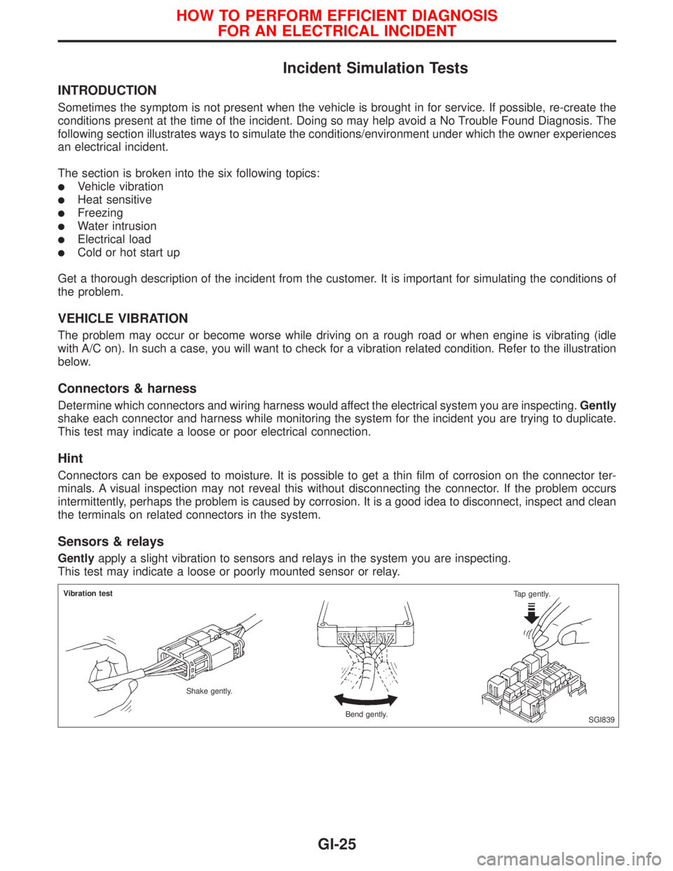
VEHICLE VIBRATION
The problem may occur or become worse while driving on a rough road or when engine is vibrating (idle
with A/C on). In such a case, you will want to check for a vibration related condition. Refer to the illustration
below.
Connectors & harness
Determine which connectors and wiring harness would affect the electrical system you are inspecting.Gently
shake each connector and harness while monitoring the system for the incident you are trying to duplicate.
This test may indicate a loose or poor electrical connection.
Hint
Connectors can be exposed to moisture. It is possible to get a thin film of corrosion on the connector ter-
minals. A visual inspection may not reveal this without disconnecting the connector. If the problem occurs
intermittently, perhaps the problem is caused by corrosion. It is a good idea to disconnect, inspect and clean
the terminals on related connectors in the system.
Sensors & relays
Gentlyapply a slight vibration to sensors and relays in the system you are inspecting.
This test may indicate a loose or poorly mounted sensor or relay.
SGI839 Vibration test
Shake gently.
Bend gently.Tap gently.
HOW TO PERFORM EFFICIENT DIAGNOSIS
FOR AN ELECTRICAL INCIDENT
GI-25