NISSAN PRIMERA 1999 Electronic Repair Manual
Manufacturer: NISSAN, Model Year: 1999, Model line: PRIMERA, Model: NISSAN PRIMERA 1999Pages: 2267, PDF Size: 35.74 MB
Page 671 of 2267
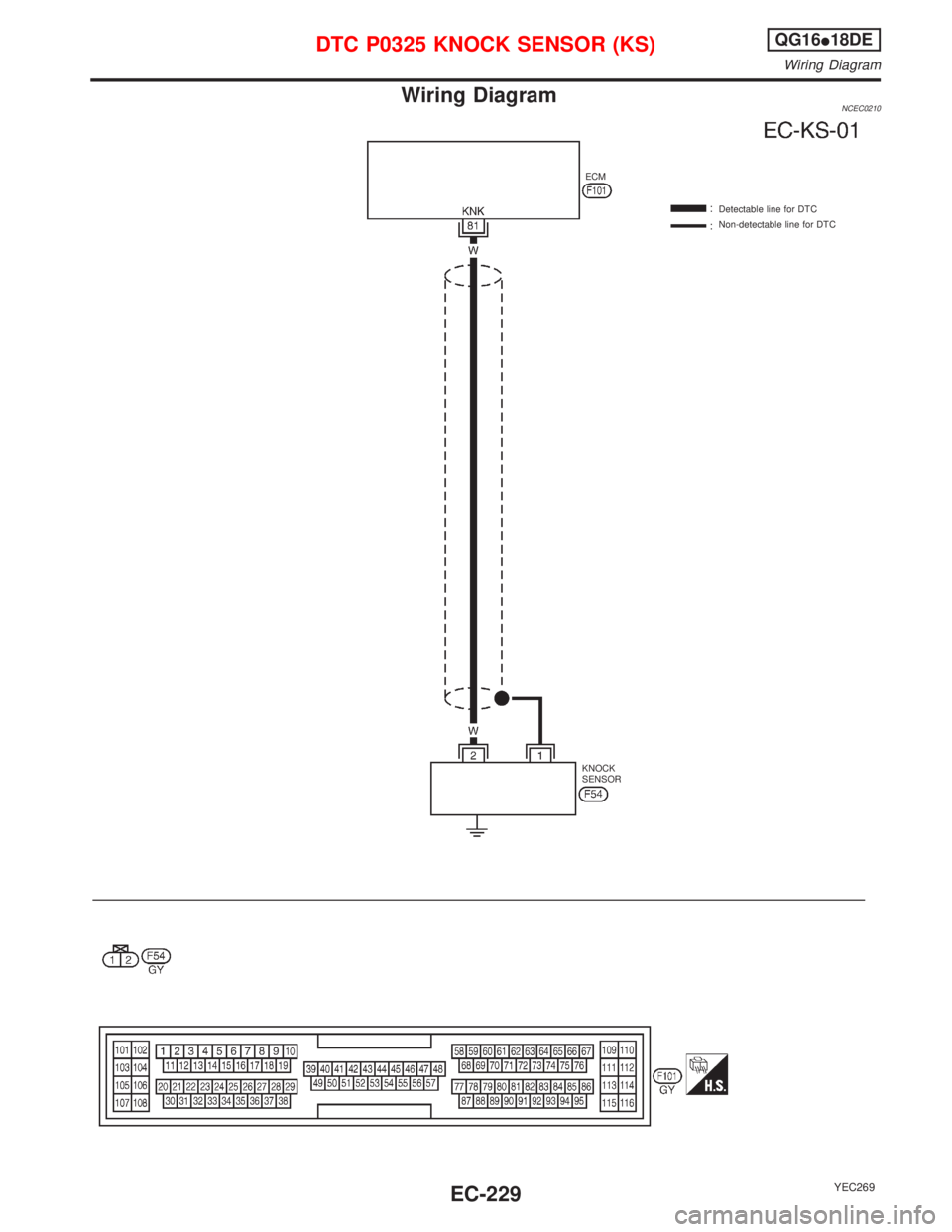
Wiring DiagramNCEC0210
YEC269
Detectable line for DTC
Non-detectable line for DTC ECM
KNOCK
SENSOR
DTC P0325 KNOCK SENSOR (KS)QG16I18DE
Wiring Diagram
EC-229
Page 672 of 2267
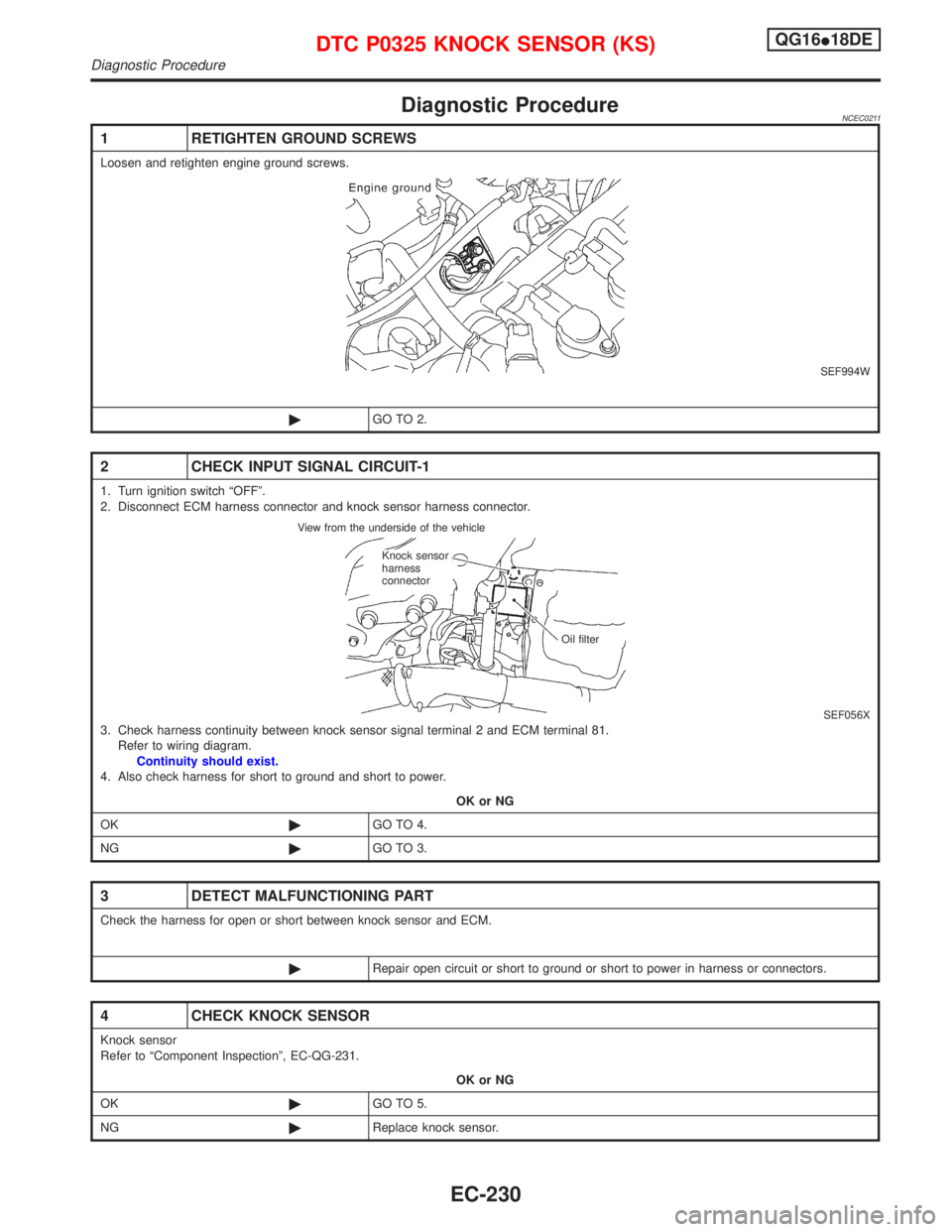
Diagnostic ProcedureNCEC0211
1 RETIGHTEN GROUND SCREWS
Loosen and retighten engine ground screws.
SEF994W
©GO TO 2.
2 CHECK INPUT SIGNAL CIRCUIT-1
1. Turn ignition switch ªOFFº.
2. Disconnect ECM harness connector and knock sensor harness connector.
SEF056X3. Check harness continuity between knock sensor signal terminal 2 and ECM terminal 81.
Refer to wiring diagram.
Continuity should exist.
4. Also check harness for short to ground and short to power.
OK or NG
OK©GO TO 4.
NG©GO TO 3.
3 DETECT MALFUNCTIONING PART
Check the harness for open or short between knock sensor and ECM.
©Repair open circuit or short to ground or short to power in harness or connectors.
4 CHECK KNOCK SENSOR
Knock sensor
Refer to ªComponent Inspectionº, EC-QG-231.
OK or NG
OK©GO TO 5.
NG©Replace knock sensor.
View from the underside of the vehicle
Knock sensor
harness
connector
Oil filter
DTC P0325 KNOCK SENSOR (KS)QG16I18DE
Diagnostic Procedure
EC-230
Page 673 of 2267
5 CHECK INTERMITTENT INCIDENT
Perform ªTROUBLE DIAGNOSIS FOR INTERMITTENT INCIDENTº, EC-QG-102.
©INSPECTION END
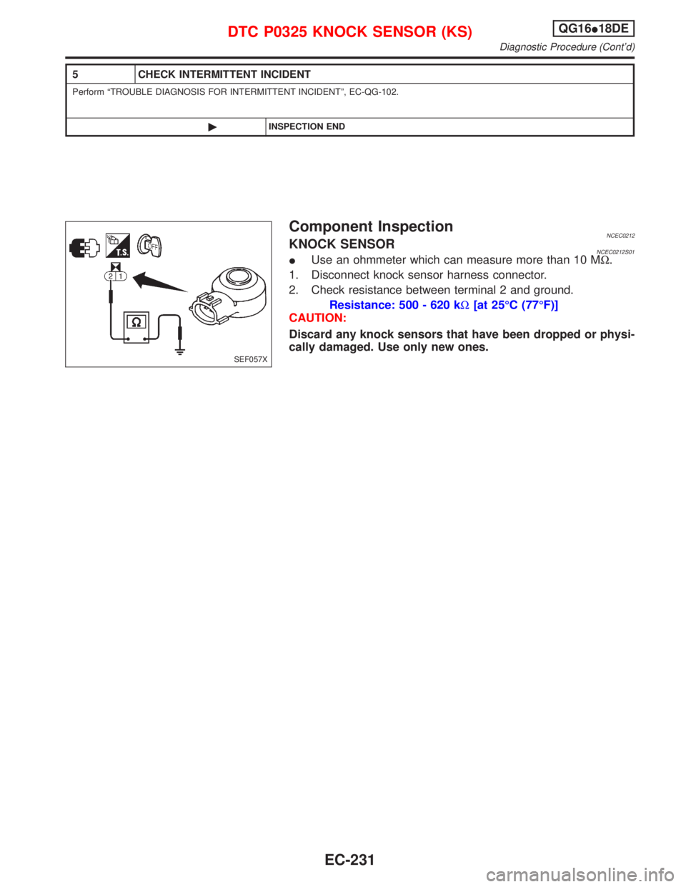
Component InspectionNCEC0212KNOCK SENSORNCEC0212S01IUse an ohmmeter which can measure more than 10 MW.
1. Disconnect knock sensor harness connector.
2. Check resistance between terminal 2 and ground.
Resistance: 500 - 620 kW[at 25ÉC (77ÉF)]
CAUTION:
Discard any knock sensors that have been dropped or physi-
cally damaged. Use only new ones.
SEF057X
DTC P0325 KNOCK SENSOR (KS)QG16I18DE
Diagnostic Procedure (Cont'd)
EC-231
Page 674 of 2267
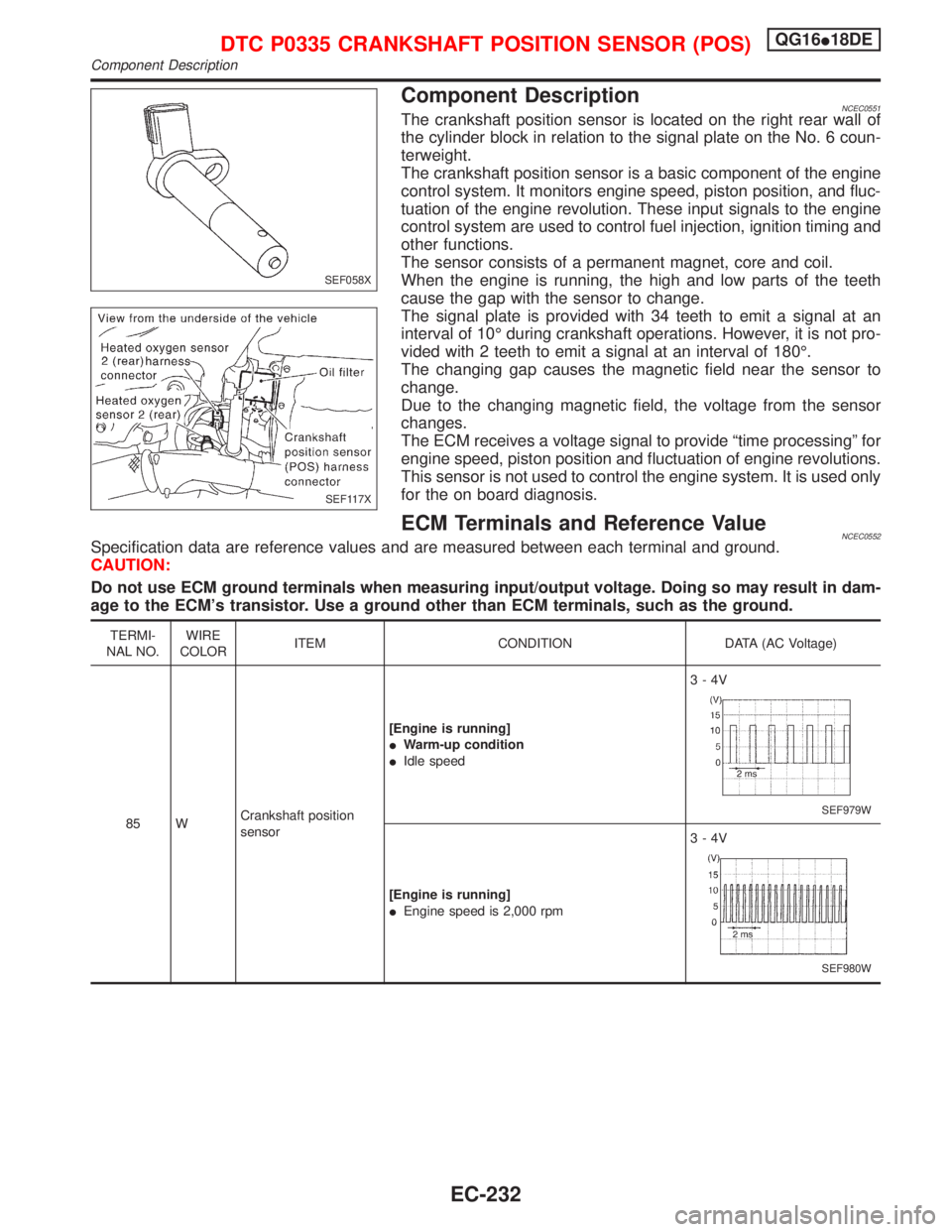
Component DescriptionNCEC0551The crankshaft position sensor is located on the right rear wall of
the cylinder block in relation to the signal plate on the No. 6 coun-
terweight.
The crankshaft position sensor is a basic component of the engine
control system. It monitors engine speed, piston position, and fluc-
tuation of the engine revolution. These input signals to the engine
control system are used to control fuel injection, ignition timing and
other functions.
The sensor consists of a permanent magnet, core and coil.
When the engine is running, the high and low parts of the teeth
cause the gap with the sensor to change.
The signal plate is provided with 34 teeth to emit a signal at an
interval of 10É during crankshaft operations. However, it is not pro-
vided with 2 teeth to emit a signal at an interval of 180É.
The changing gap causes the magnetic field near the sensor to
change.
Due to the changing magnetic field, the voltage from the sensor
changes.
The ECM receives a voltage signal to provide ªtime processingº for
engine speed, piston position and fluctuation of engine revolutions.
This sensor is not used to control the engine system. It is used only
for the on board diagnosis.
ECM Terminals and Reference ValueNCEC0552Specification data are reference values and are measured between each terminal and ground.
CAUTION:
Do not use ECM ground terminals when measuring input/output voltage. Doing so may result in dam-
age to the ECM's transistor. Use a ground other than ECM terminals, such as the ground.
TERMI-
NAL NO.WIRE
COLORITEM CONDITION DATA (AC Voltage)
85 WCrankshaft position
sensor[Engine is running]
IWarm-up condition
IIdle speed3-4V
SEF979W
[Engine is running]
IEngine speed is 2,000 rpm3-4V
SEF980W
SEF058X
SEF117X
DTC P0335 CRANKSHAFT POSITION SENSOR (POS)QG16I18DE
Component Description
EC-232
Page 675 of 2267
On Board Diagnosis LogicNCEC0553
DTC No. Malfunction is detected when ... Check Items (Possible Cause)
P0335
0335IThe 10É signal is not entered to ECM for the first few seconds
during engine cranking.
..........................................................................................................
IThe 10É signal is not entered to ECM during engine running.
..........................................................................................................
IThe 10É signal is not in the normal pattern at each engine
revolution.IHarness or connectors
(The crankshaft position sensor (POS) circuit is
open or shorted.)
ICrankshaft position sensor (POS)
IStarter motor (Refer to EL section.)
IStarting system circuit (Refer to EL section.)
IDead (Weak) battery
DTC Confirmation ProcedureNCEC0554NOTE:
If ªDTC Confirmation Procedureº has been previously conducted,
always turn ignition switch ªOFFº and wait at least 9 seconds
before conducting the next test.
With CONSULT-II
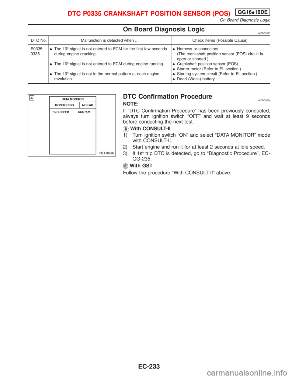
1) Turn ignition switch ªONº and select ªDATA MONITORº mode
with CONSULT-II.
2) Start engine and run it for at least 2 seconds at idle speed.
3) If 1st trip DTC is detected, go to ªDiagnostic Procedureº, EC-
QG-235.
With GST
Follow the procedure ªWith CONSULT-IIº above.
NEF068A
DTC P0335 CRANKSHAFT POSITION SENSOR (POS)QG16I18DE
On Board Diagnosis Logic
EC-233
Page 676 of 2267

Wiring DiagramNCEC0555
YEC070A
DTC P0335 CRANKSHAFT POSITION SENSOR (POS)QG16I18DE
Wiring Diagram
EC-234
Page 677 of 2267
Diagnostic ProcedureNCEC0556
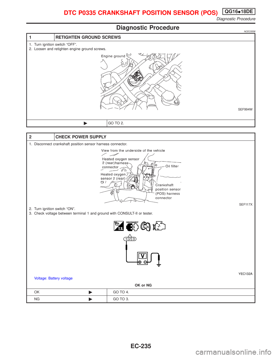
1 RETIGHTEN GROUND SCREWS
1. Turn ignition switch ªOFFº.
2. Loosen and retighten engine ground screws.
SEF994W
©GO TO 2.
2 CHECK POWER SUPPLY
1. Disconnect crankshaft position sensor harness connector.
SEF117X2. Turn ignition switch ªONº.
3. Check voltage between terminal 1 and ground with CONSULT-II or tester.
YEC132AVoltage: Battery voltage
OK or NG
OK©GO TO 4.
NG©GO TO 3.
DTC P0335 CRANKSHAFT POSITION SENSOR (POS)QG16I18DE
Diagnostic Procedure
EC-235
Page 678 of 2267
3 DETECT MALFUNCTIONING PART
Check the following.
IHarness connectors E90, F73
IHarness for open or short between crankshaft position sensor and ECM relay
IHarness for open or short between crankshaft position sensor and ECM
IECM relay
©Repair open circuit or short to ground or short to power in harness or connectors.
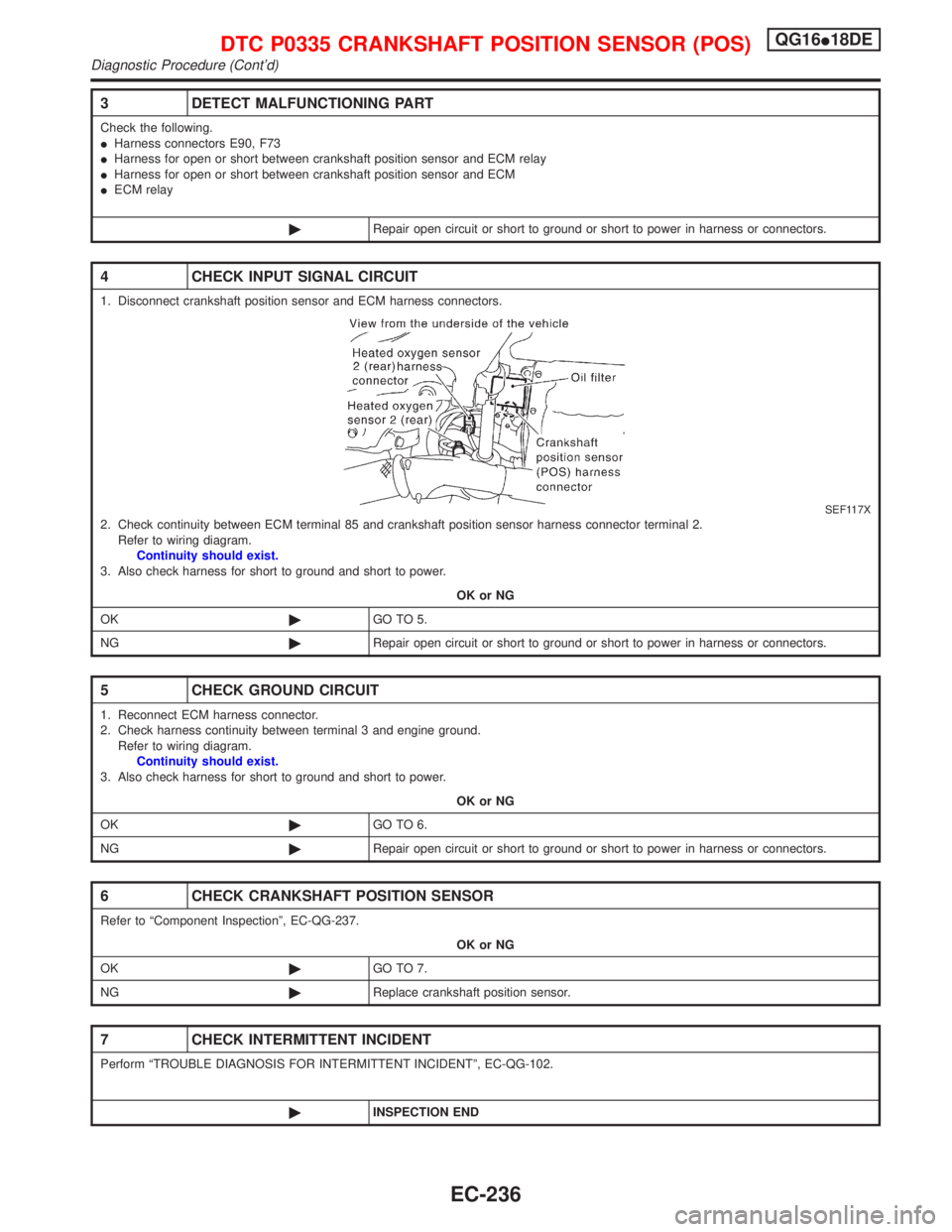
4 CHECK INPUT SIGNAL CIRCUIT
1. Disconnect crankshaft position sensor and ECM harness connectors.
SEF117X2. Check continuity between ECM terminal 85 and crankshaft position sensor harness connector terminal 2.
Refer to wiring diagram.
Continuity should exist.
3. Also check harness for short to ground and short to power.
OK or NG
OK©GO TO 5.
NG©Repair open circuit or short to ground or short to power in harness or connectors.
5 CHECK GROUND CIRCUIT
1. Reconnect ECM harness connector.
2. Check harness continuity between terminal 3 and engine ground.
Refer to wiring diagram.
Continuity should exist.
3. Also check harness for short to ground and short to power.
OK or NG
OK©GO TO 6.
NG©Repair open circuit or short to ground or short to power in harness or connectors.
6 CHECK CRANKSHAFT POSITION SENSOR
Refer to ªComponent Inspectionº, EC-QG-237.
OK or NG
OK©GO TO 7.
NG©Replace crankshaft position sensor.
7 CHECK INTERMITTENT INCIDENT
Perform ªTROUBLE DIAGNOSIS FOR INTERMITTENT INCIDENTº, EC-QG-102.
©INSPECTION END
DTC P0335 CRANKSHAFT POSITION SENSOR (POS)QG16I18DE
Diagnostic Procedure (Cont'd)
EC-236
Page 679 of 2267
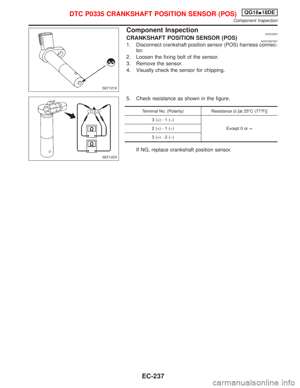
Component InspectionNCEC0557CRANKSHAFT POSITION SENSOR (POS)NCEC0557S011. Disconnect crankshaft position sensor (POS) harness connec-
tor.
2. Loosen the fixing bolt of the sensor.
3. Remove the sensor.
4. Visually check the sensor for chipping.
5. Check resistance as shown in the figure.
Terminal No. (Polarity) ResistanceW[at 25ÉC (77ÉF)]
3 (+) - 1 (þ)
Except 0 or¥ 2 (+) - 1 (þ)
3 (+) - 2 (þ)
If NG, replace crankshaft position sensor.
SEF121X
SEF122X
DTC P0335 CRANKSHAFT POSITION SENSOR (POS)QG16I18DE
Component Inspection
EC-237
Page 680 of 2267
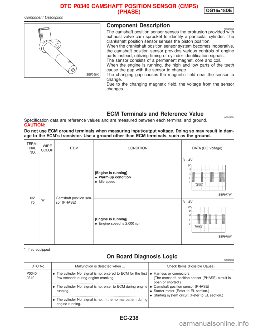
Component DescriptionNCEC0220The camshaft position sensor senses the protrusion provided with
exhaust valve cam sprocket to identify a particular cylinder. The
crankshaft position sensor senses the piston position.
When the crankshaft position sensor system becomes inoperative,
the camshaft position sensor provides various controls of engine
parts instead, utilizing timing of cylinder identification signals.
The sensor consists of a permanent magnet, core and coil.
When the engine is running, the high and low parts of the teeth
cause the gap with the sensor to change.
The changing gap causes the magnetic field near the sensor to
change.
Due to the changing magnetic field, the voltage from the sensor
changes.
ECM Terminals and Reference ValueNCEC0221Specification data are reference values and are measured between each terminal and ground.
CAUTION:
Do not use ECM ground terminals when measuring input/output voltage. Doing so may result in dam-
age to the ECM's transistor. Use a ground other than ECM terminals, such as the ground.
TERMI-
NAL
NO.WIRE
COLORITEM CONDITION DATA (DC Voltage)
66*
75WCamshaft position sen-
sor (PHASE)[Engine is running]
IWarm-up condition
IIdle speed3-4V
SEF977W
[Engine is running]
IEngine speed is 2,000 rpm3-4V
SEF978W
*: If so equipped
On Board Diagnosis LogicNCEC0222
DTC No. Malfunction is detected when ... Check Items (Possible Cause)
P0340
0340IThe cylinder No. signal is not entered to ECM for the first
few seconds during engine cranking.
.................................................................................................
IThe cylinder No. signal is not enter to ECM during engine
running.
.................................................................................................
IThe cylinder No. signal is not in the normal pattern during
engine running.IHarness or connectors
(The camshaft position sensor (PHASE) circuit is
open or shorted.)
ICamshaft position sensor (PHASE)
IStarter motor (Refer to EL section.)
IStarting system circuit (Refer to EL section.)
SEF058X
DTC P0340 CAMSHAFT POSITION SENSOR (CMPS)
(PHASE)QG16I18DE
Component Description
EC-238