NISSAN PRIMERA 1999 Electronic Manual PDF
Manufacturer: NISSAN, Model Year: 1999, Model line: PRIMERA, Model: NISSAN PRIMERA 1999Pages: 2267, PDF Size: 35.74 MB
Page 61 of 2267
DescriptionNCAT0220The primary speed sensor detects the primary pulley revolution
speed and sends a signal to the ECM.
TCM TERMINALS AND REFERENCE VALUENCAT0220S01Remarks: Specification data are reference values.
Terminal
No.Wire color Item ConditionJudgement
standard
38 G/YPrimary speed
sensorWhen driving (L position, 20 km/h), the pulse measurement by
using the pulse measurement function of CONSULT-II.Approx. 900 Hz
ON BOARD DIAGNOSIS LOGICNCAT0220S02
Diagnostic trouble code Malfunction is detected when ... Check items (Possible cause)
: PRI SPEED SIG/CIRC
TCM does not receive the proper voltage
signal from the sensor.IHarness or connectors
(The sensor circuit is open or shorted.)
IPrimary speed sensor
: P0715
: MI Code No. 0715
DIAGNOSTIC TROUBLE CODE (DTC) CONFIRMATION
PROCEDURE
NCAT0220S03CAUTION:
IAlways drive vehicle at a safe speed.
IBe careful not to rev engine into the red zone on the
tachometer.
NOTE:
If ªDIAGNOSTIC TROUBLE CODE CONFIRMATION PROCE-
DUREº has been previously conducted, always turn ignition
switch ªOFFº and wait at least 5 seconds before conducting
the next test.
After the repair, perform the following procedure to confirm the
malfunction is eliminated.
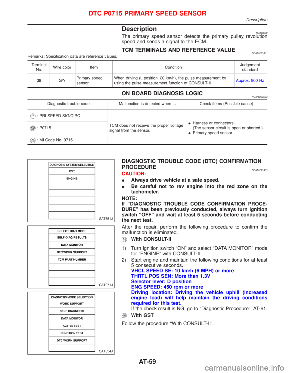
With CONSULT-II
1) Turn ignition switch ªONº and select ªDATA MONITORº mode
for ªENGINEº with CONSULT-II.
2) Start engine and maintain the following conditions for at least
5 consecutive seconds.
VHCL SPEED SE: 10 km/h (6 MPH) or more
THRTL POS SEN: More than 1.3V
Selector lever: D position
ENG SPEED: 450 rpm or more
Driving location: Driving the vehicle uphill (increased
engine load) will help maintain the driving conditions
required for this test.
If the check result is NG, go to ªDiagnostic Procedureº, AT-61.
With GST
Follow the procedure ªWith CONSULT-IIº.
SAT651J
SAT971J
SAT654J
DTC P0715 PRIMARY SPEED SENSOR
Description
AT-59
Page 62 of 2267
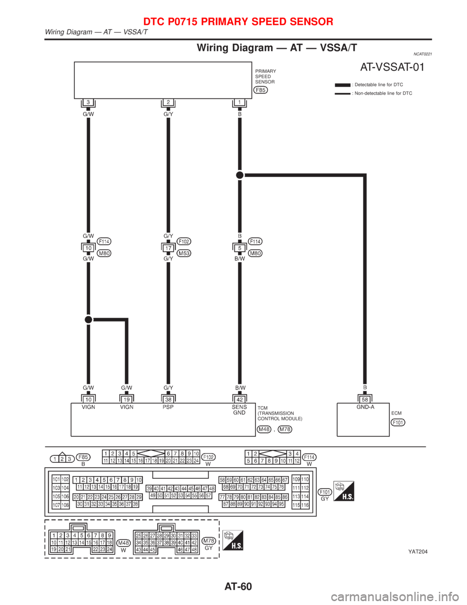
Wiring Diagram Ð AT Ð VSSA/TNCAT0221
YAT204
PRIMARY
SPEED
SENSOR
: Detectable line for DTC
: Non-detectable line for DTC
TCM
(TRANSMISSION
CONTROL MODULE)ECM
DTC P0715 PRIMARY SPEED SENSOR
Wiring Diagram Ð AT Ð VSSA/T
AT-60
Page 63 of 2267
Diagnostic ProcedureNCAT0222
1 CHECK PRIMARY SPEED SENSOR
Refer to ªComponent Inspectionº AT-65.
OK or NG
OK (With CONSULT-II)©GO TO 2.
OK (Without CONSULT-II)©GO TO 3.
NG©Repair or replace primary speed sensor.
2 CHECK INPUT SIGNAL (With CONSULT-II)
With CONSULT-II
1. Start engine.
2. Select ªECU INPUT SIGNALSº in ªDATA MONITORº mode for ªCVTº with CONSULT-II.
3. Read out the value of ªI/P PULLY SPDº while driving.
Check the value changes according to driving speed. (Almost same value as engine speed)
OK or NG
OK©GO TO 4.
NG©Check the following items:
IHarness for short or open between TCM, ECM and primary speed sensor (Main har-
ness)
IGround circuit for ECM
Refer to EC section (ªTROUBLE DIAGNOSIS FOR POWER SUPPLYº).
3 CHECK DTC
Perform Diagnostic Trouble Code (DTC) confirmation procedure, AT-62.
OK or NG
OK©INSPECTION END
NG©1. Perform TCM input/output signal inspection.
2. If NG, recheck TCM pin terminals for damage or loose connection with harness con-
nector.
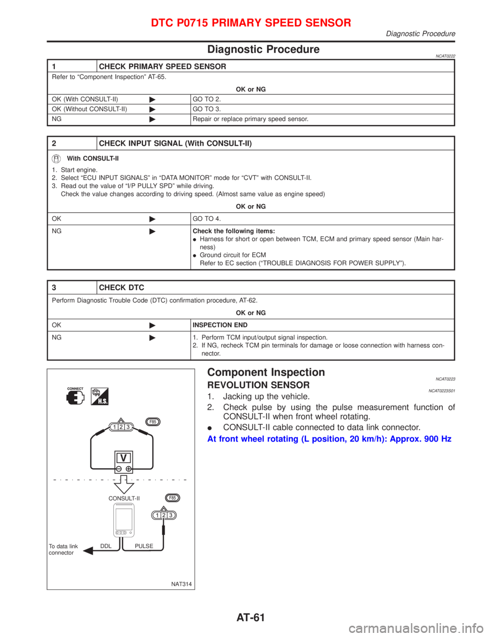
Component InspectionNCAT0223REVOLUTION SENSORNCAT0223S011. Jacking up the vehicle.
2. Check pulse by using the pulse measurement function of
CONSULT-II when front wheel rotating.
ICONSULT-II cable connected to data link connector.
At front wheel rotating (L position, 20 km/h): Approx. 900 Hz
NAT314 CONSULT-II
To data link
connectorDDL PULSE
DTC P0715 PRIMARY SPEED SENSOR
Diagnostic Procedure
AT-61
Page 64 of 2267
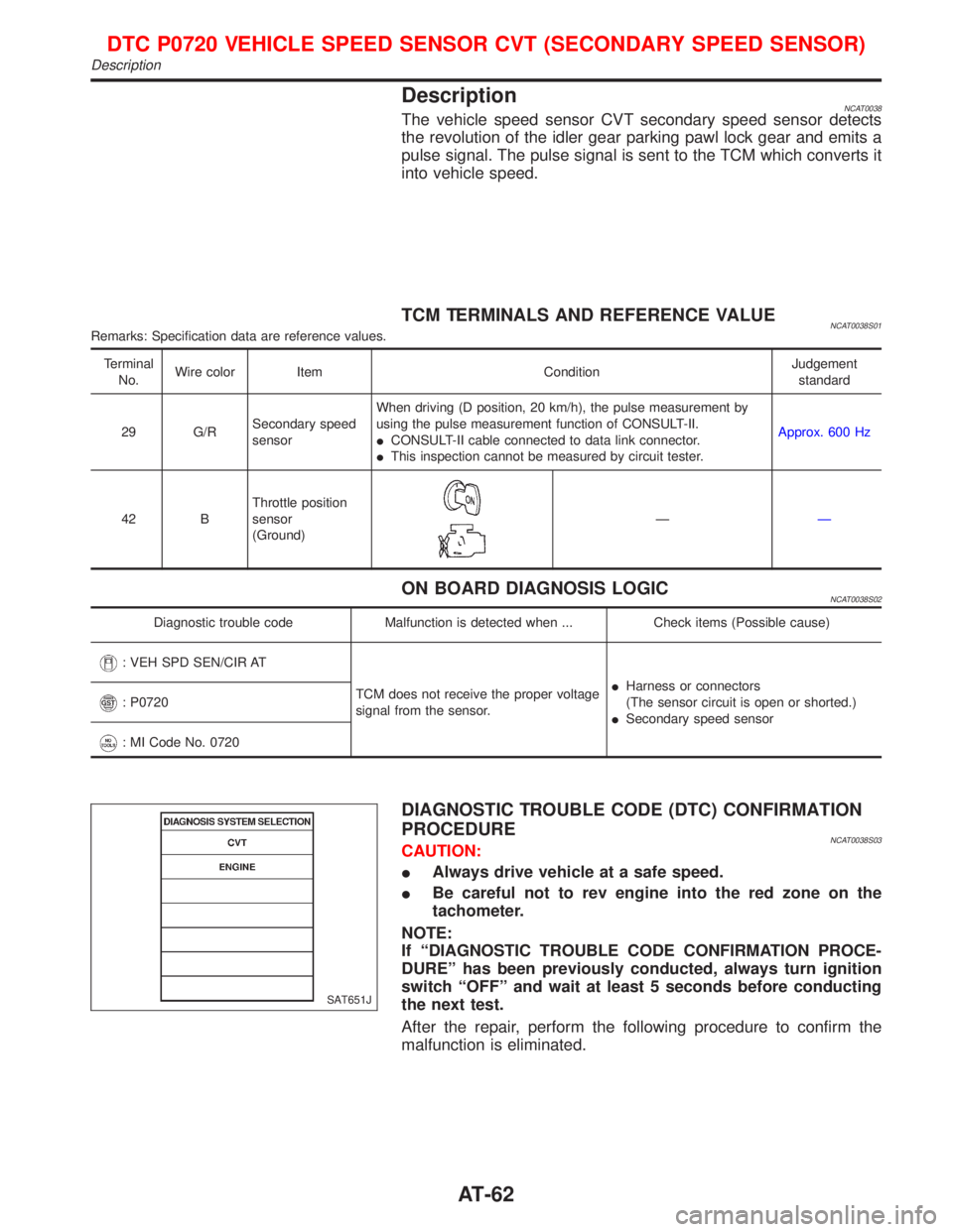
DescriptionNCAT0038The vehicle speed sensor CVT secondary speed sensor detects
the revolution of the idler gear parking pawl lock gear and emits a
pulse signal. The pulse signal is sent to the TCM which converts it
into vehicle speed.
TCM TERMINALS AND REFERENCE VALUENCAT0038S01Remarks: Specification data are reference values.
Terminal
No.Wire color Item ConditionJudgement
standard
29 G/RSecondary speed
sensorWhen driving (D position, 20 km/h), the pulse measurement by
using the pulse measurement function of CONSULT-II.
ICONSULT-II cable connected to data link connector.
IThis inspection cannot be measured by circuit tester.Approx. 600 Hz
42 BThrottle position
sensor
(Ground)
ÐÐ
ON BOARD DIAGNOSIS LOGICNCAT0038S02
Diagnostic trouble code Malfunction is detected when ... Check items (Possible cause)
: VEH SPD SEN/CIR AT
TCM does not receive the proper voltage
signal from the sensor.IHarness or connectors
(The sensor circuit is open or shorted.)
ISecondary speed sensor
: P0720
: MI Code No. 0720
DIAGNOSTIC TROUBLE CODE (DTC) CONFIRMATION
PROCEDURE
NCAT0038S03CAUTION:
IAlways drive vehicle at a safe speed.
IBe careful not to rev engine into the red zone on the
tachometer.
NOTE:
If ªDIAGNOSTIC TROUBLE CODE CONFIRMATION PROCE-
DUREº has been previously conducted, always turn ignition
switch ªOFFº and wait at least 5 seconds before conducting
the next test.
After the repair, perform the following procedure to confirm the
malfunction is eliminated.
SAT651J
DTC P0720 VEHICLE SPEED SENSOR CVT (SECONDARY SPEED SENSOR)
Description
AT-62
Page 65 of 2267
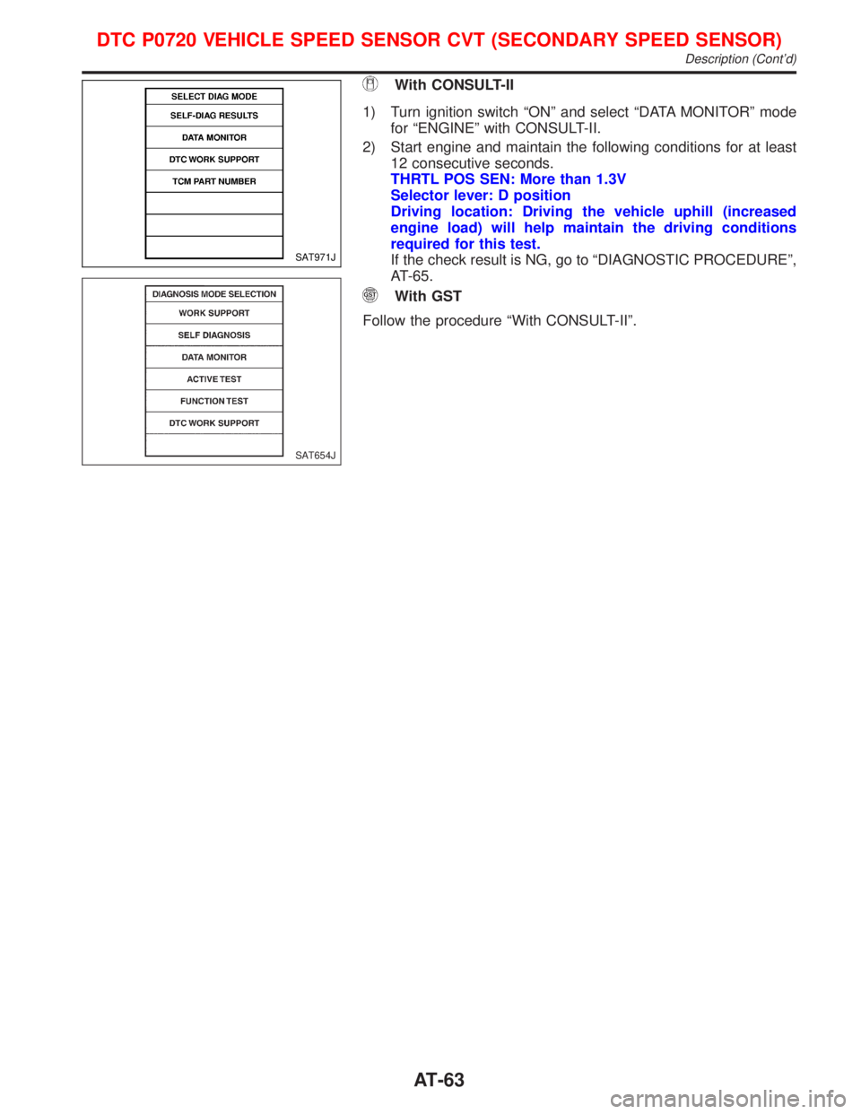
With CONSULT-II
1) Turn ignition switch ªONº and select ªDATA MONITORº mode
for ªENGINEº with CONSULT-II.
2) Start engine and maintain the following conditions for at least
12 consecutive seconds.
THRTL POS SEN: More than 1.3V
Selector lever: D position
Driving location: Driving the vehicle uphill (increased
engine load) will help maintain the driving conditions
required for this test.
If the check result is NG, go to ªDIAGNOSTIC PROCEDUREº,
AT-65.
With GST
Follow the procedure ªWith CONSULT-IIº.
SAT971J
SAT654J
DTC P0720 VEHICLE SPEED SENSOR CVT (SECONDARY SPEED SENSOR)
Description (Cont'd)
AT-63
Page 66 of 2267
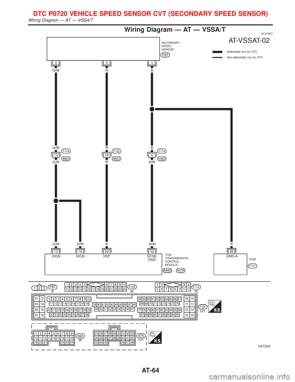
Wiring Diagram Ð AT Ð VSSA/TNCAT0201
YAT205
SECONDARY
SPEED
SENSOR
: Detectable line for DTC
: Non-detectable line for DTC
TCM
(TRANSMISSION
CONTROL
MODULE)ECM
DTC P0720 VEHICLE SPEED SENSOR CVT (SECONDARY SPEED SENSOR)
Wiring Diagram Ð AT Ð VSSA/T
AT-64
Page 67 of 2267
Diagnostic ProcedureNCAT0039
1 CHECK SECONDARY SPEED SENSOR
Refer to ªComponent Inspectionº AT-65.
OK or NG
OK (With CONSULT-II)©GO TO 2.
OK (Without CONSULT-II)©GO TO 3.
NG©Repair or replace secondary speed sensor.
2 CHECK INPUT SIGNAL (With CONSULT-II)
With CONSULT-II
1. Start engine.
2. Select ªECU INPUT SIGNALSº in ªDATA MONITORº mode for ªCVTº with CONSULT-II.
3. Read out the value of ªVEHICLE SPEEDº while driving.
Check the value changes according to driving speed.
OK or NG
OK©GO TO 4.
NG©Check the following items:
IHarness for short or open between TCM, ECM and secondary speed sensor (Main
harness)
IGround circuit for ECM
Refer to EC section (ªTROUBLE DIAGNOSIS FOR POWER SUPPLYº).
3 CHECK DTC
Perform Diagnostic Trouble Code (DTC) confirmation procedure, AT-62.
OK or NG
OK©INSPECTION END
NG©1. Perform TCM input/output signal inspection.
2. If NG, recheck TCM pin terminals for damage or loose connection with harness con-
nector.
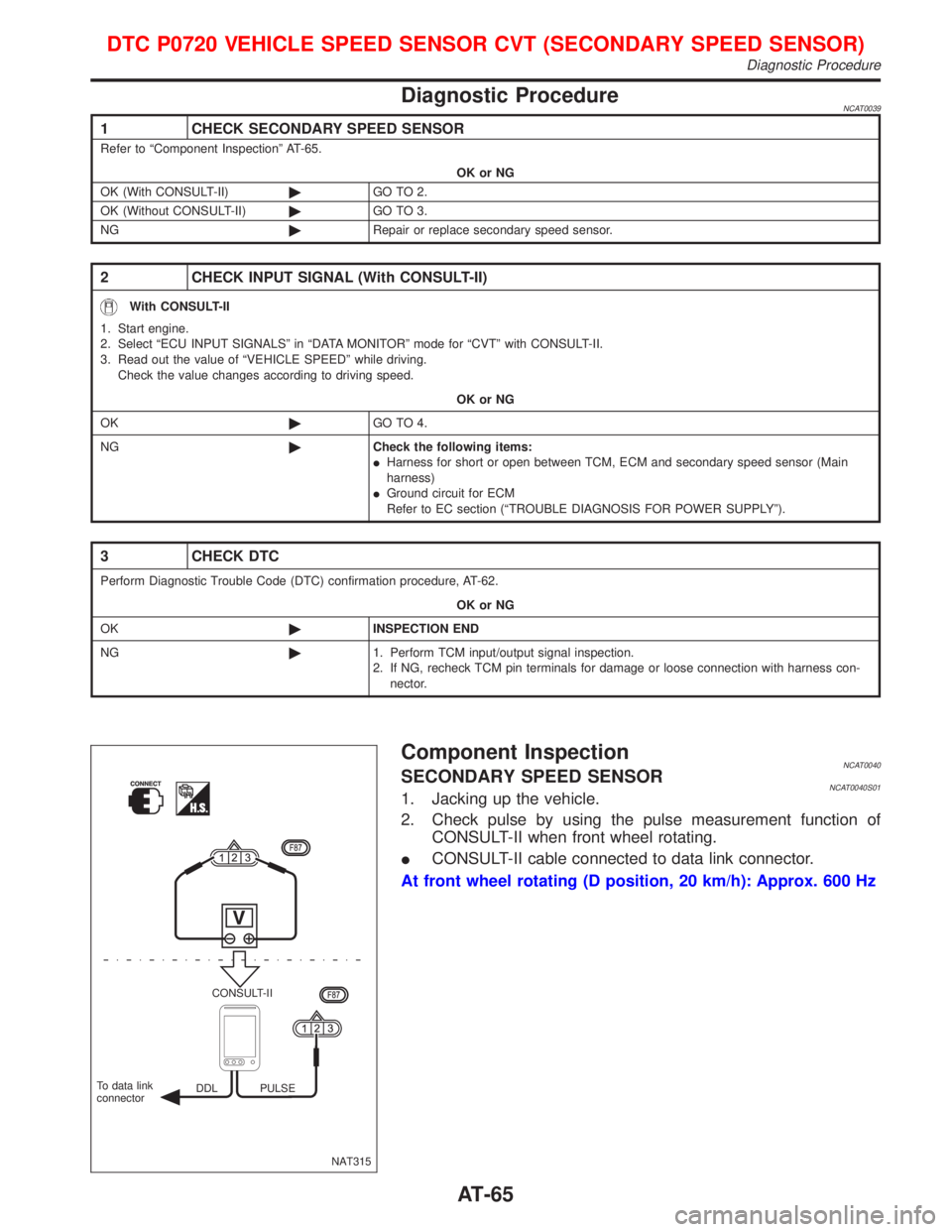
Component InspectionNCAT0040SECONDARY SPEED SENSORNCAT0040S011. Jacking up the vehicle.
2. Check pulse by using the pulse measurement function of
CONSULT-II when front wheel rotating.
ICONSULT-II cable connected to data link connector.
At front wheel rotating (D position, 20 km/h): Approx. 600 Hz
NAT315 CONSULT-II
DDL PULSE To data link
connector
DTC P0720 VEHICLE SPEED SENSOR CVT (SECONDARY SPEED SENSOR)
Diagnostic Procedure
AT-65
Page 68 of 2267
DescriptionNCAT0041The engine speed signal is sent from the ECM to the TCM.
TCM TERMINALS AND REFERENCE VALUENCAT0041S01Remarks: Specification data are reference values.
Terminal
No.Wire color Item ConditionJudgement
standard
39 L/OREngine speed
signal
When engine runs at idle speed.0.5 - 1.5V
ON BOARD DIAGNOSIS LOGICNCAT0041S02
Diagnostic trouble code Malfunction is detected when ... Check item (Possible cause)
: ENGINE SPEED SIG
TCM does not receive the proper voltage
signal from ECM.IHarness or connectors
(The sensor circuit is open or shorted.)
: P0725
: MI Code No. 0725
DIAGNOSTIC TROUBLE CODE (DTC) CONFIRMATION
PROCEDURE
NCAT0041S03CAUTION:
Always drive vehicle at a safe speed.
NOTE:
If ªDIAGNOSTIC TROUBLE CODE CONFIRMATION PROCE-
DUREº has been previously conducted, always turn ignition
switch ªOFFº and wait at least 5 seconds before conducting
the next test.
After the repair, perform the following procedure to confirm the
malfunction is eliminated.
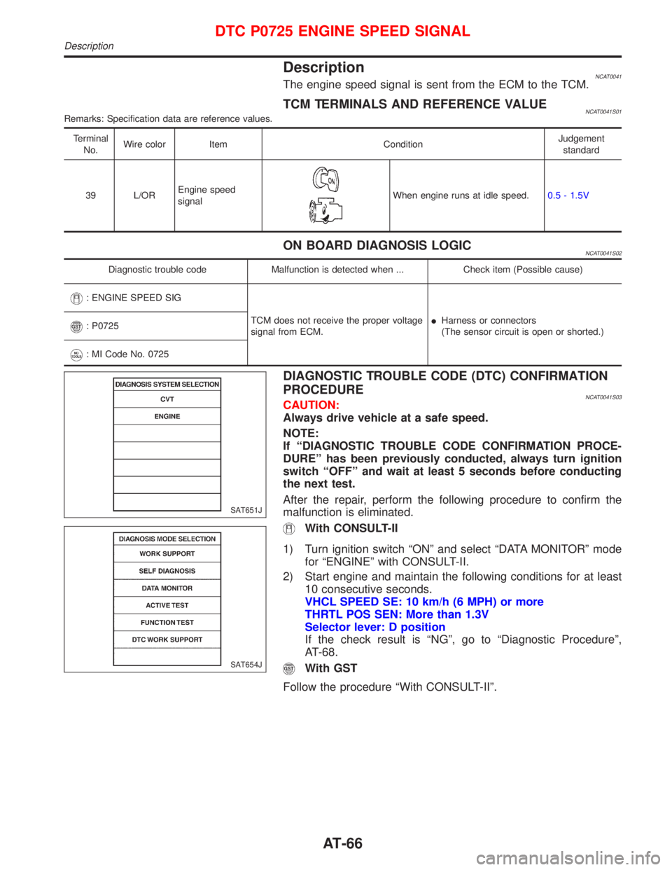
With CONSULT-II
1) Turn ignition switch ªONº and select ªDATA MONITORº mode
for ªENGINEº with CONSULT-II.
2) Start engine and maintain the following conditions for at least
10 consecutive seconds.
VHCL SPEED SE: 10 km/h (6 MPH) or more
THRTL POS SEN: More than 1.3V
Selector lever: D position
If the check result is ªNGº, go to ªDiagnostic Procedureº,
AT-68.
With GST
Follow the procedure ªWith CONSULT-IIº.
SAT651J
SAT654J
DTC P0725 ENGINE SPEED SIGNAL
Description
AT-66
Page 69 of 2267
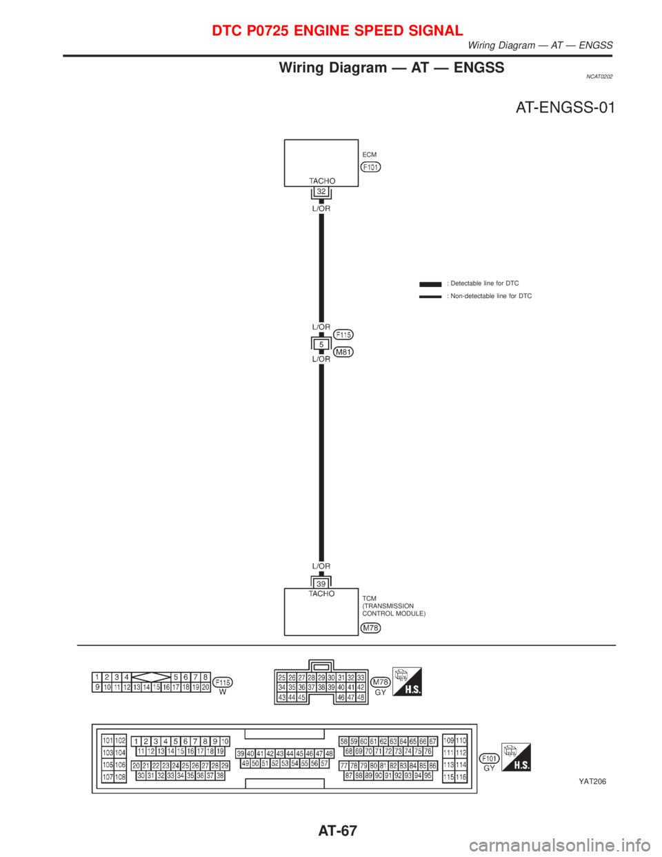
Wiring Diagram Ð AT Ð ENGSSNCAT0202
YAT206
ECM
: Detectable line for DTC
: Non-detectable line for DTC
TCM
(TRANSMISSION
CONTROL MODULE)
DTC P0725 ENGINE SPEED SIGNAL
Wiring Diagram Ð AT Ð ENGSS
AT-67
Page 70 of 2267
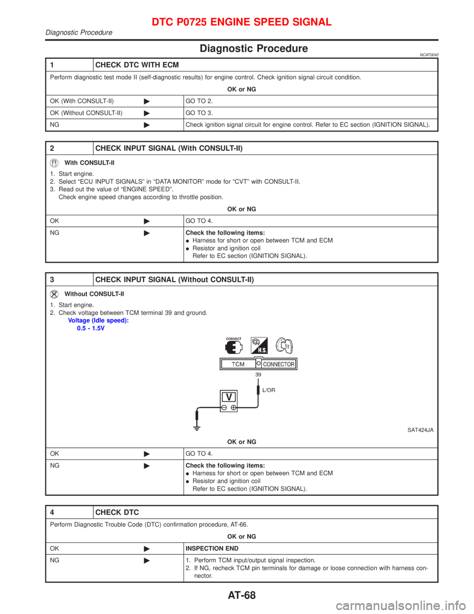
Diagnostic ProcedureNCAT0042
1 CHECK DTC WITH ECM
Perform diagnostic test mode II (self-diagnostic results) for engine control. Check ignition signal circuit condition.
OK or NG
OK (With CONSULT-II)©GO TO 2.
OK (Without CONSULT-II)©GO TO 3.
NG©Check ignition signal circuit for engine control. Refer to EC section (IGNITION SIGNAL).
2 CHECK INPUT SIGNAL (With CONSULT-II)
With CONSULT-II
1. Start engine.
2. Select ªECU INPUT SIGNALSº in ªDATA MONITORº mode for ªCVTº with CONSULT-II.
3. Read out the value of ªENGINE SPEEDº.
Check engine speed changes according to throttle position.
OK or NG
OK©GO TO 4.
NG©Check the following items:
IHarness for short or open between TCM and ECM
IResistor and ignition coil
Refer to EC section (IGNITION SIGNAL).
3 CHECK INPUT SIGNAL (Without CONSULT-II)
Without CONSULT-II
1. Start engine.
2. Check voltage between TCM terminal 39 and ground.
Voltage (Idle speed):
0.5 - 1.5V
SAT424JA
OK or NG
OK©GO TO 4.
NG©Check the following items:
IHarness for short or open between TCM and ECM
IResistor and ignition coil
Refer to EC section (IGNITION SIGNAL).
4 CHECK DTC
Perform Diagnostic Trouble Code (DTC) confirmation procedure, AT-66.
OK or NG
OK©INSPECTION END
NG©1. Perform TCM input/output signal inspection.
2. If NG, recheck TCM pin terminals for damage or loose connection with harness con-
nector.
DTC P0725 ENGINE SPEED SIGNAL
Diagnostic Procedure
AT-68