NISSAN PRIMERA 1999 Electronic Repair Manual
PRIMERA 1999
NISSAN
NISSAN
https://www.carmanualsonline.info/img/5/57377/w960_57377-0.png
NISSAN PRIMERA 1999 Electronic Repair Manual
Trending: airbag, radio controls, center console, wheel torque, steering wheel adjustment, fuel filter location, suspension
Page 761 of 2267
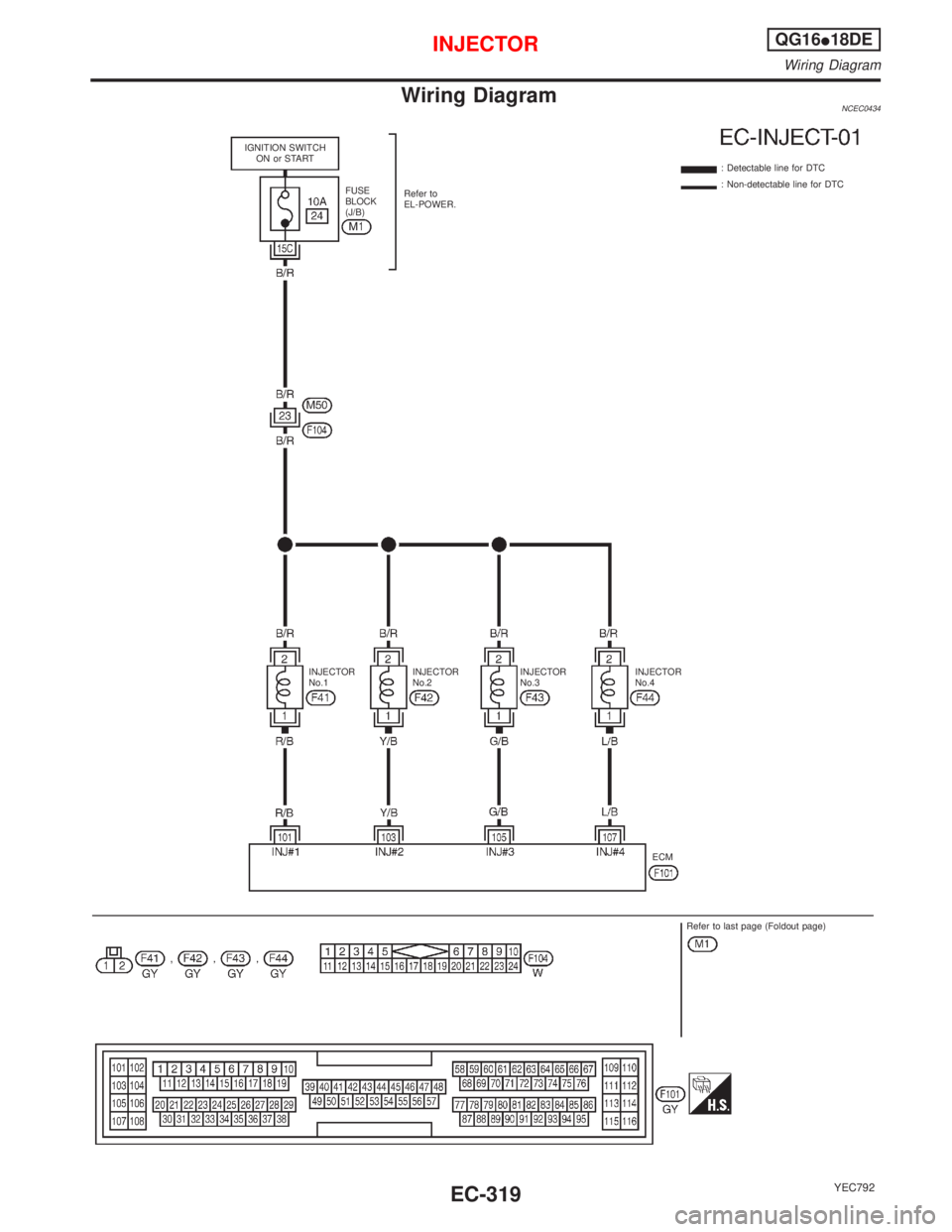
Wiring DiagramNCEC0434
YEC792
IGNITION SWITCH
ON or START
Refer to
EL-POWER.: Detectable line for DTC
: Non-detectable line for DTC
FUSE
BLOCK
(J/B)
ECM
Refer to last page (Foldout page) INJECTOR
No.1INJECTOR
No.2INJECTOR
No.3INJECTOR
No.4
INJECTORQG16I18DE
Wiring Diagram
EC-319
Page 762 of 2267
Diagnostic ProcedureNCEC0438
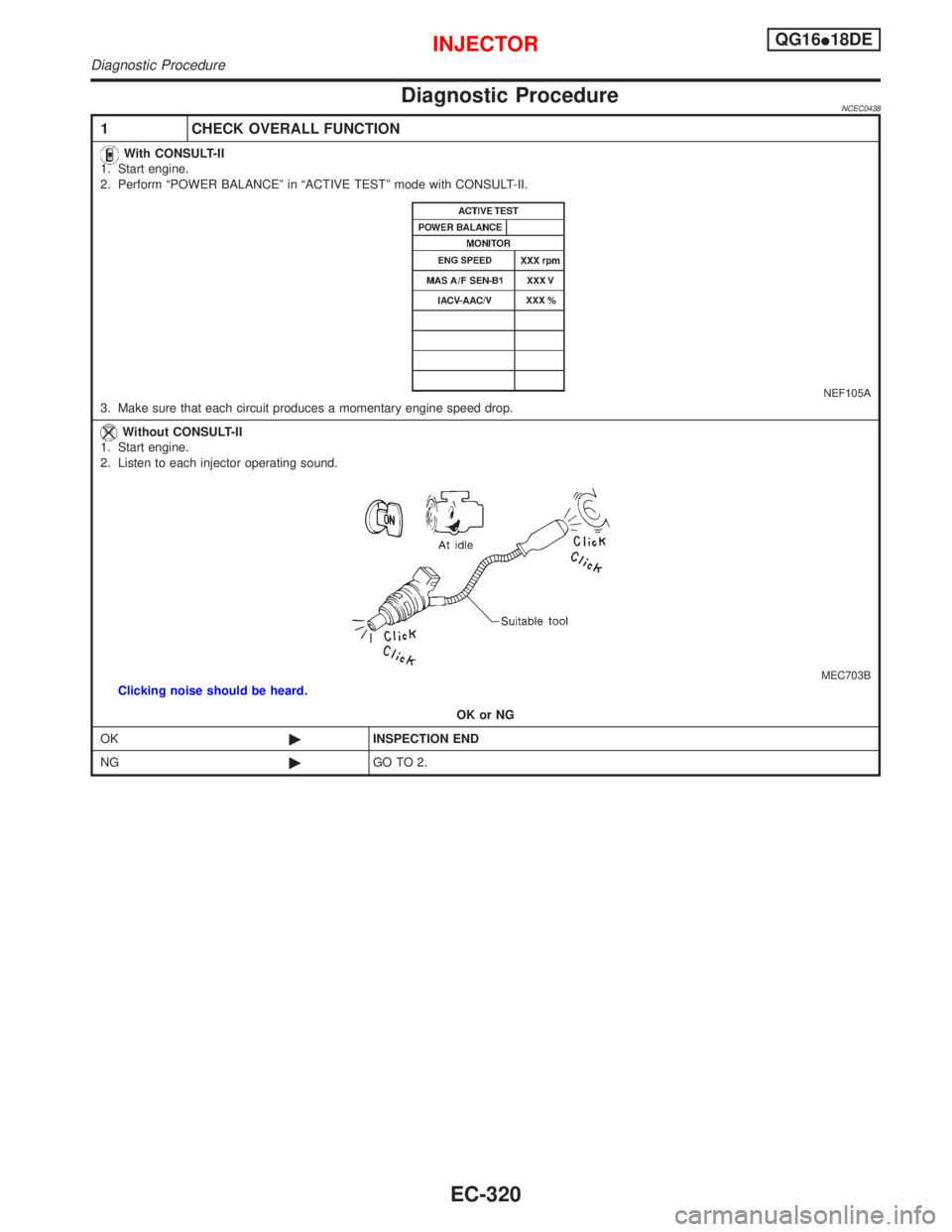
1 CHECK OVERALL FUNCTION
With CONSULT-II
1. Start engine.
2. Perform ªPOWER BALANCEº in ªACTIVE TESTº mode with CONSULT-II.
NEF105A3. Make sure that each circuit produces a momentary engine speed drop.
Without CONSULT-II
1. Start engine.
2. Listen to each injector operating sound.
MEC703BClicking noise should be heard.
OK or NG
OK©INSPECTION END
NG©GO TO 2.
INJECTORQG16I18DE
Diagnostic Procedure
EC-320
Page 763 of 2267
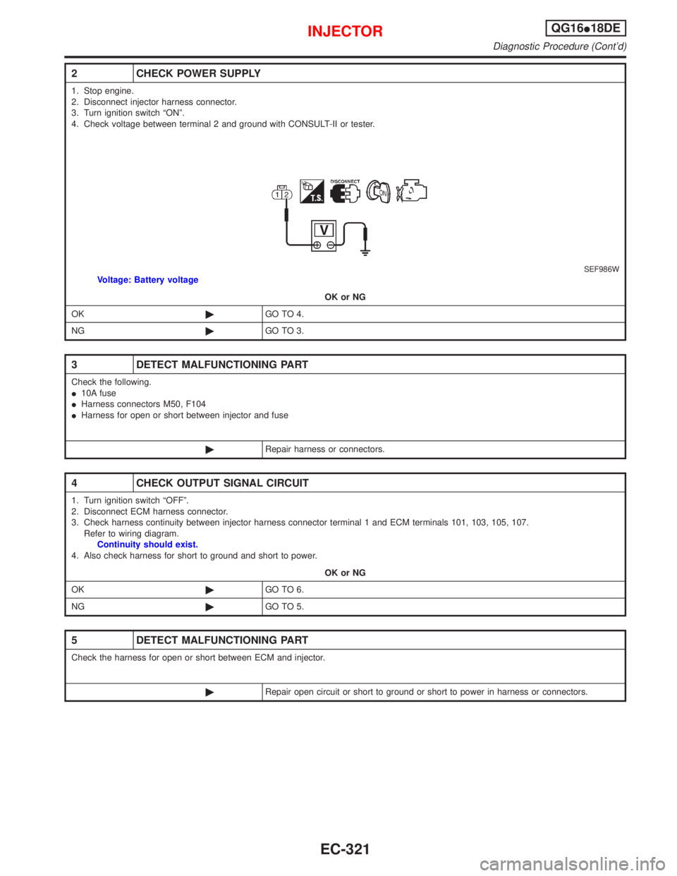
2 CHECK POWER SUPPLY
1. Stop engine.
2. Disconnect injector harness connector.
3. Turn ignition switch ªONº.
4. Check voltage between terminal 2 and ground with CONSULT-II or tester.
SEF986WVoltage: Battery voltage
OK or NG
OK©GO TO 4.
NG©GO TO 3.
3 DETECT MALFUNCTIONING PART
Check the following.
I10A fuse
IHarness connectors M50, F104
IHarness for open or short between injector and fuse
©Repair harness or connectors.
4 CHECK OUTPUT SIGNAL CIRCUIT
1. Turn ignition switch ªOFFº.
2. Disconnect ECM harness connector.
3. Check harness continuity between injector harness connector terminal 1 and ECM terminals 101, 103, 105, 107.
Refer to wiring diagram.
Continuity should exist.
4. Also check harness for short to ground and short to power.
OK or NG
OK©GO TO 6.
NG©GO TO 5.
5 DETECT MALFUNCTIONING PART
Check the harness for open or short between ECM and injector.
©Repair open circuit or short to ground or short to power in harness or connectors.
INJECTORQG16I18DE
Diagnostic Procedure (Cont'd)
EC-321
Page 764 of 2267
6 CHECK INJECTOR
Refer to ªComponent Inspectionº, EC-QG-322.
OK or NG
OK©GO TO 7.
NG©Replace injector.
7 CHECK INTERMITTENT INCIDENT
Perform ªTROUBLE DIAGNOSIS FOR INTERMITTENT INCIDENTº, EC-QG-102.
©INSPECTION END
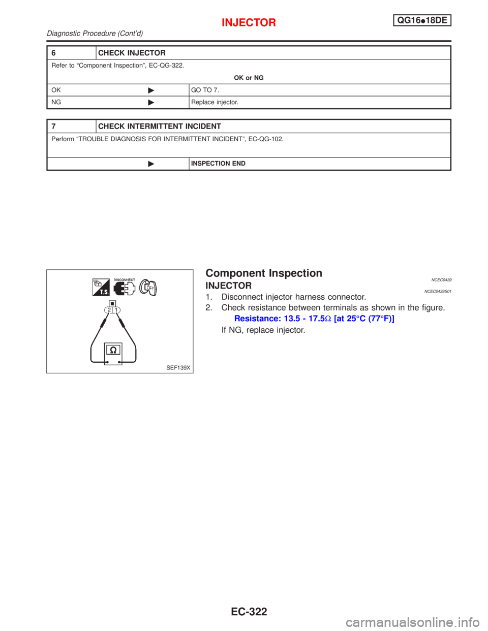
Component InspectionNCEC0439INJECTORNCEC0439S011. Disconnect injector harness connector.
2. Check resistance between terminals as shown in the figure.
Resistance: 13.5 - 17.5W[at 25ÉC (77ÉF)]
If NG, replace injector.
SEF139X
INJECTORQG16I18DE
Diagnostic Procedure (Cont'd)
EC-322
Page 765 of 2267
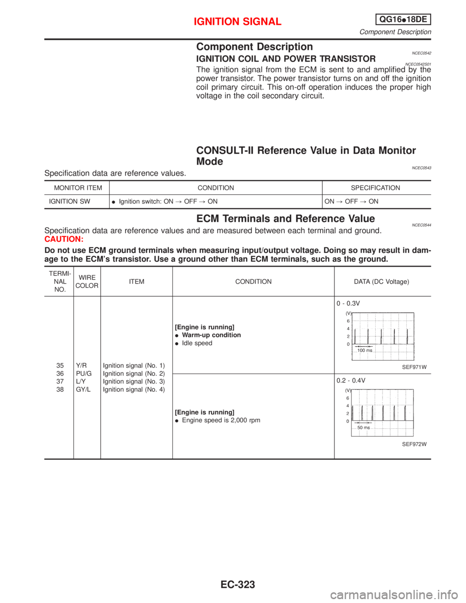
Component DescriptionNCEC0542IGNITION COIL AND POWER TRANSISTORNCEC0542S01The ignition signal from the ECM is sent to and amplified by the
power transistor. The power transistor turns on and off the ignition
coil primary circuit. This on-off operation induces the proper high
voltage in the coil secondary circuit.
CONSULT-II Reference Value in Data Monitor
Mode
NCEC0543Specification data are reference values.
MONITOR ITEM CONDITION SPECIFICATION
IGNITION SWIIgnition switch: ON,OFF,ON ON,OFF,ON
ECM Terminals and Reference ValueNCEC0544Specification data are reference values and are measured between each terminal and ground.
CAUTION:
Do not use ECM ground terminals when measuring input/output voltage. Doing so may result in dam-
age to the ECM's transistor. Use a ground other than ECM terminals, such as the ground.
TERMI-
NAL
NO.WIRE
COLORITEM CONDITION DATA (DC Voltage)
35
36
37
38Y/R
PU/G
L/Y
GY/LIgnition signal (No. 1)
Ignition signal (No. 2)
Ignition signal (No. 3)
Ignition signal (No. 4)[Engine is running]
IWarm-up condition
IIdle speed0 - 0.3V
SEF971W
[Engine is running]
IEngine speed is 2,000 rpm0.2 - 0.4V
SEF972W
IGNITION SIGNALQG16I18DE
Component Description
EC-323
Page 766 of 2267
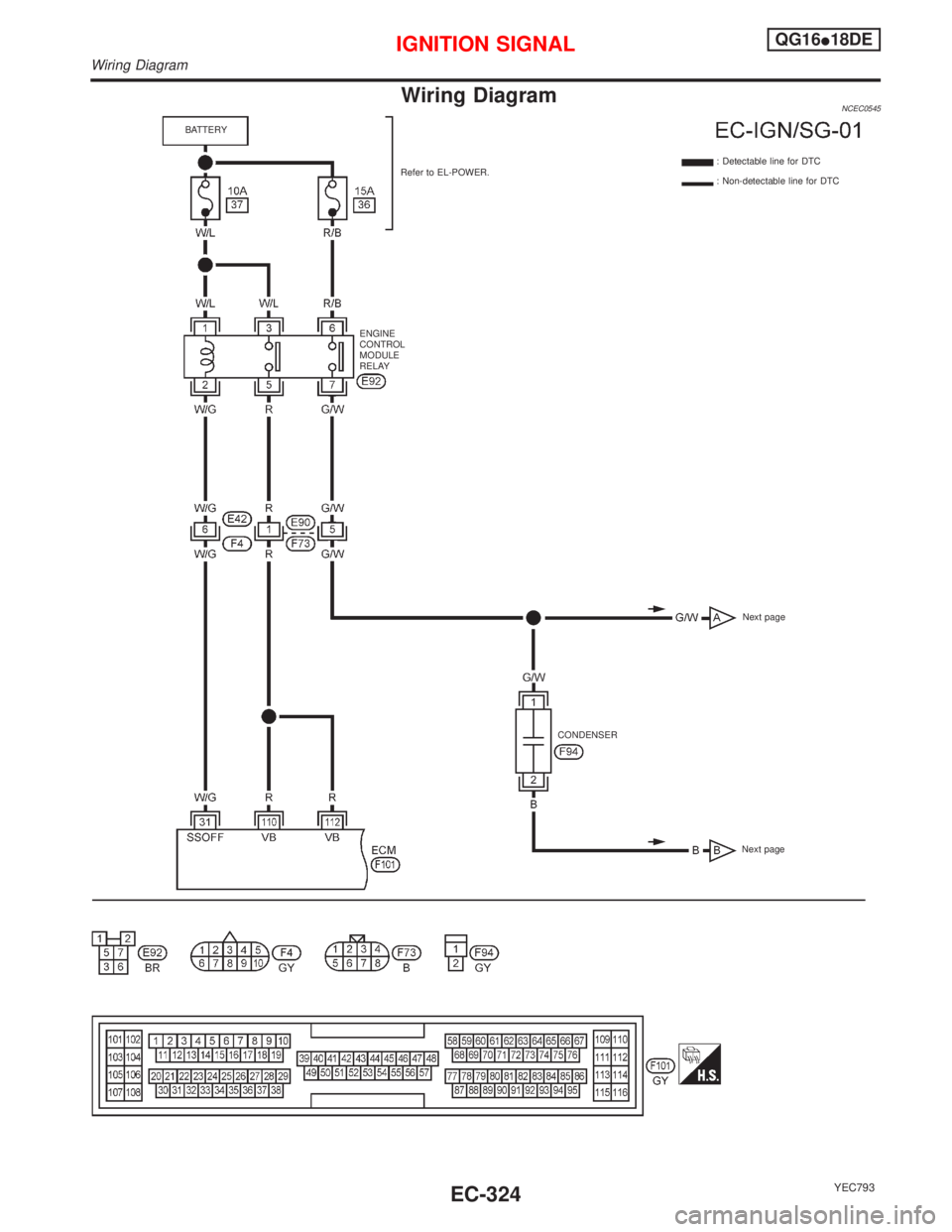
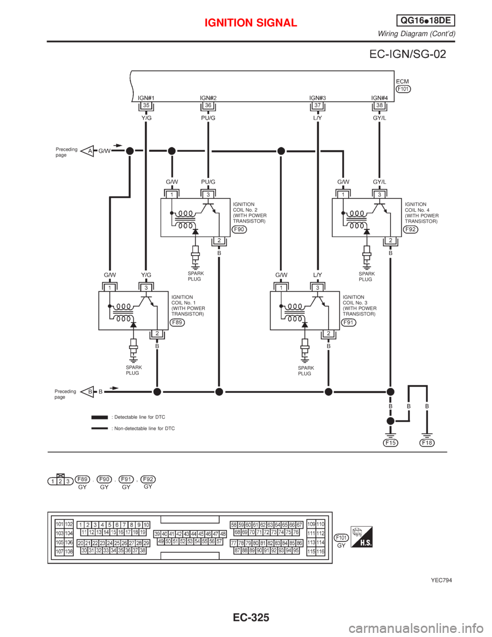
Wiring DiagramNCEC0545
YEC793
ENGINE
CONTROL
MODULE
RELAY
CONDENSER Refer to EL-POWER. BATTERY
: Detectable line for DTC
: Non-detectable line for DTC
Next pageNext page
IGNITION SIGNALQG16I18DE
Wiring Diagram
EC-324
Page 767 of 2267
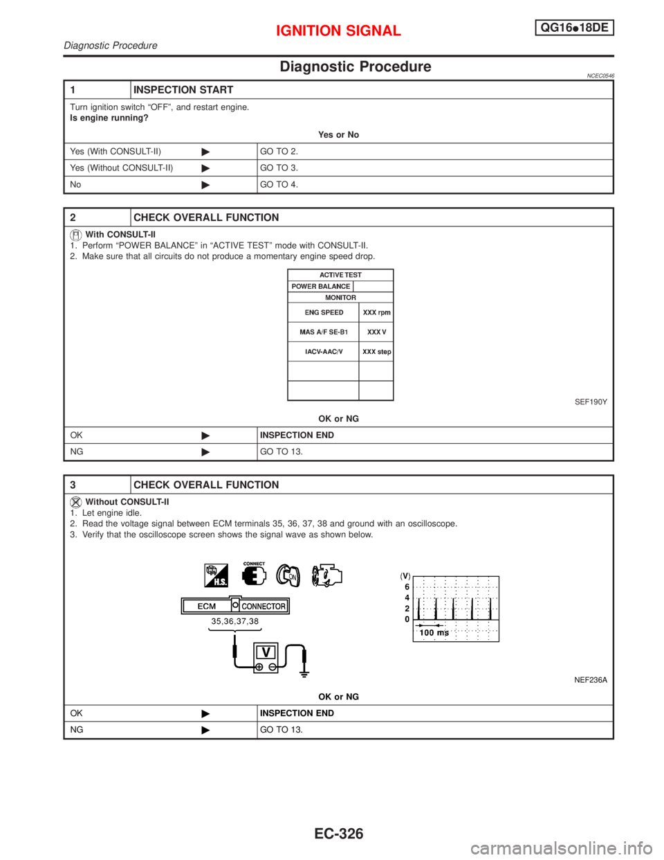
YEC794
Preceding
page
IGNITION
COIL No. 4
(WITH POWER
TRANSISTOR) IGNITION
COIL No. 2
(WITH POWER
TRANSISTOR)
SPARK
PLUG
IGNITION
COIL No. 1
(WITH POWER
TRANSISTOR)IGNITION
COIL No. 3
(WITH POWER
TRANSISTOR)SPARK
PLUG
SPARK
PLUGSPARK
PLUG
Preceding
page
: Detectable line for DTC
: Non-detectable line for DTC
IGNITION SIGNALQG16I18DE
Wiring Diagram (Cont'd)
EC-325
Page 768 of 2267
Diagnostic ProcedureNCEC0546
1 INSPECTION START
Turn ignition switch ªOFFº, and restart engine.
Is engine running?
YesorNo
Yes (With CONSULT-II)©GO TO 2.
Yes (Without CONSULT-II)©GO TO 3.
No©GO TO 4.
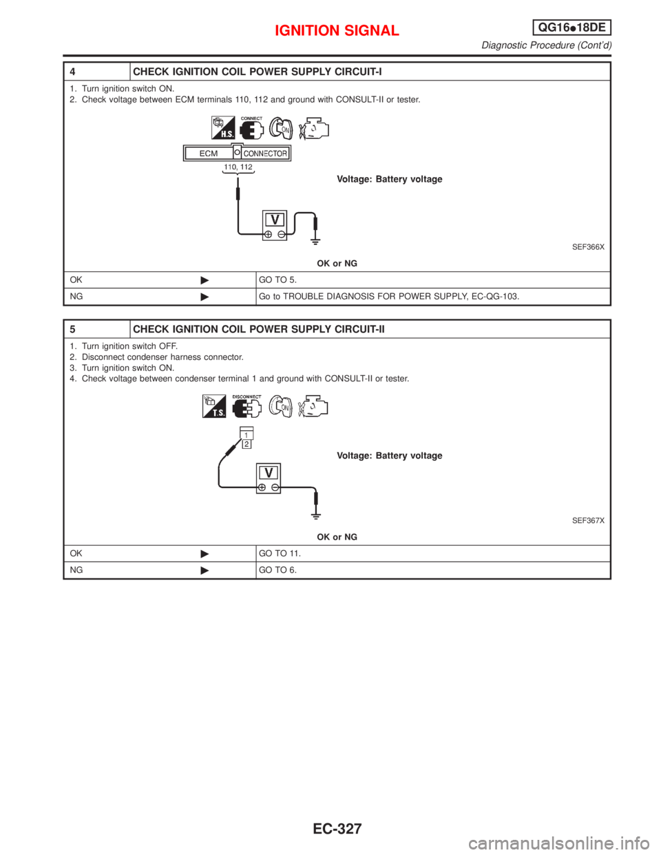
2 CHECK OVERALL FUNCTION
With CONSULT-II
1. Perform ªPOWER BALANCEº in ªACTIVE TESTº mode with CONSULT-II.
2. Make sure that all circuits do not produce a momentary engine speed drop.
SEF190Y
OK or NG
OK©INSPECTION END
NG©GO TO 13.
3 CHECK OVERALL FUNCTION
Without CONSULT-II
1. Let engine idle.
2. Read the voltage signal between ECM terminals 35, 36, 37, 38 and ground with an oscilloscope.
3. Verify that the oscilloscope screen shows the signal wave as shown below.
NEF236A
OK or NG
OK©INSPECTION END
NG©GO TO 13.
IGNITION SIGNALQG16I18DE
Diagnostic Procedure
EC-326
Page 769 of 2267
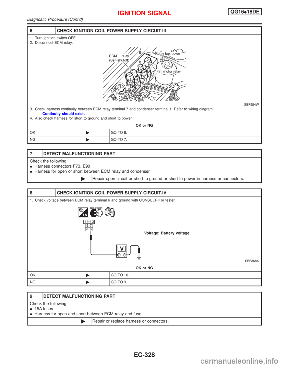
4 CHECK IGNITION COIL POWER SUPPLY CIRCUIT-I
1. Turn ignition switch ON.
2. Check voltage between ECM terminals 110, 112 and ground with CONSULT-II or tester.
SEF366X
OK or NG
OK©GO TO 5.
NG©Go to TROUBLE DIAGNOSIS FOR POWER SUPPLY, EC-QG-103.
5 CHECK IGNITION COIL POWER SUPPLY CIRCUIT-II
1. Turn ignition switch OFF.
2. Disconnect condenser harness connector.
3. Turn ignition switch ON.
4. Check voltage between condenser terminal 1 and ground with CONSULT-II or tester.
SEF367X
OK or NG
OK©GO TO 11.
NG©GO TO 6.
IGNITION SIGNALQG16I18DE
Diagnostic Procedure (Cont'd)
EC-327
Page 770 of 2267
6 CHECK IGNITION COIL POWER SUPPLY CIRCUIT-III
1. Turn ignition switch OFF.
2. Disconnect ECM relay.
SEF984W3. Check harness continuity between ECM relay terminal 7 and condenser terminal 1. Refer to wiring diagram.
Continuity should exist.
4. Also check harness for short to ground and short to power.
OK or NG
OK©GO TO 8.
NG©GO TO 7.
7 DETECT MALFUNCTIONING PART
Check the following.
IHarness connectors F73, E90
IHarness for open or short between ECM relay and condenser
©Repair open circuit or short to ground or short to power in harness or connectors.
8 CHECK IGNITION COIL POWER SUPPLY CIRCUIT-IV
1. Check voltage between ECM relay terminal 6 and ground with CONSULT-II or tester.
SEF368X
OK or NG
OK©GO TO 10.
NG©GO TO 9.
9 DETECT MALFUNCTIONING PART
Check the following.
I15A fuses
IHarness for open and short between ECM relay and fuse
©Repair or replace harness or connectors.
IGNITION SIGNALQG16I18DE
Diagnostic Procedure (Cont'd)
EC-328
Trending: trunk, charging, brake, jack points, trip computer, lights, brake sensor
