NISSAN PRIMERA 1999 Electronic Repair Manual
Manufacturer: NISSAN, Model Year: 1999, Model line: PRIMERA, Model: NISSAN PRIMERA 1999Pages: 2267, PDF Size: 35.74 MB
Page 771 of 2267
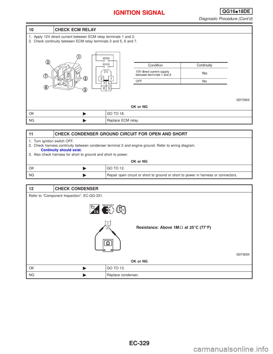
10 CHECK ECM RELAY
1. Apply 12V direct current between ECM relay terminals 1 and 2.
2. Check continuity between ECM relay terminals 3 and 5, 6 and 7.
SEF296X
OK or NG
OK©GO TO 18.
NG©Replace ECM relay.
11 CHECK CONDENSER GROUND CIRCUIT FOR OPEN AND SHORT
1. Turn ignition switch OFF.
2. Check harness continuity between condenser terminal 2 and engine ground. Refer to wiring diagram.
Continuity should exist.
3. Also check harness for short to ground and short to power.
OK or NG
OK©GO TO 12.
NG©Repair open circuit or short to ground or short to power in harness or connectors.
12 CHECK CONDENSER
Refer to ªComponent Inspectionº, EC-QG-331.
SEF369X
OK or NG
OK©GO TO 13.
NG©Replace condenser.
IGNITION SIGNALQG16I18DE
Diagnostic Procedure (Cont'd)
EC-329
Page 772 of 2267
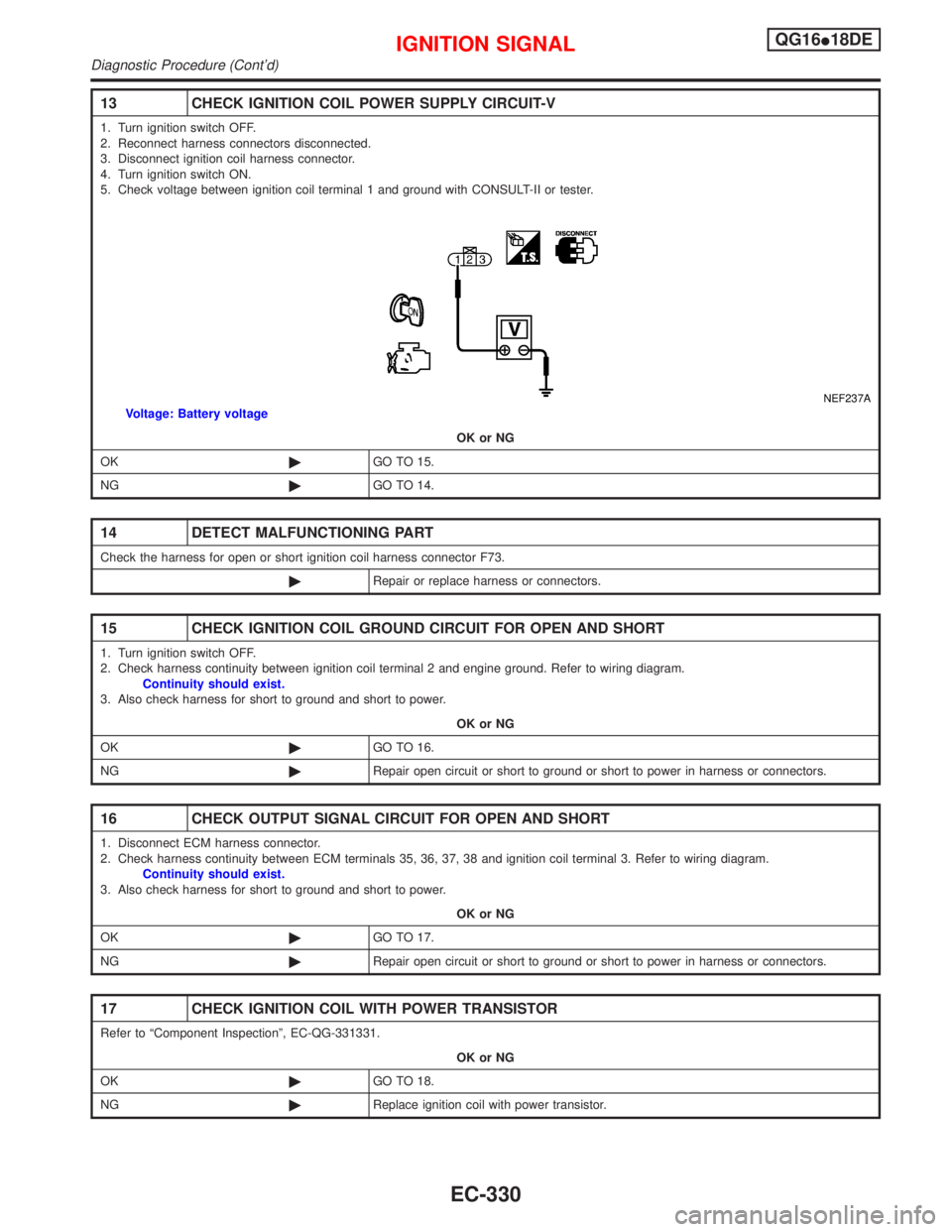
13 CHECK IGNITION COIL POWER SUPPLY CIRCUIT-V
1. Turn ignition switch OFF.
2. Reconnect harness connectors disconnected.
3. Disconnect ignition coil harness connector.
4. Turn ignition switch ON.
5. Check voltage between ignition coil terminal 1 and ground with CONSULT-II or tester.
NEF237AVoltage: Battery voltage
OK or NG
OK©GO TO 15.
NG©GO TO 14.
14 DETECT MALFUNCTIONING PART
Check the harness for open or short ignition coil harness connector F73.
©Repair or replace harness or connectors.
15 CHECK IGNITION COIL GROUND CIRCUIT FOR OPEN AND SHORT
1. Turn ignition switch OFF.
2. Check harness continuity between ignition coil terminal 2 and engine ground. Refer to wiring diagram.
Continuity should exist.
3. Also check harness for short to ground and short to power.
OK or NG
OK©GO TO 16.
NG©Repair open circuit or short to ground or short to power in harness or connectors.
16 CHECK OUTPUT SIGNAL CIRCUIT FOR OPEN AND SHORT
1. Disconnect ECM harness connector.
2. Check harness continuity between ECM terminals 35, 36, 37, 38 and ignition coil terminal 3. Refer to wiring diagram.
Continuity should exist.
3. Also check harness for short to ground and short to power.
OK or NG
OK©GO TO 17.
NG©Repair open circuit or short to ground or short to power in harness or connectors.
17 CHECK IGNITION COIL WITH POWER TRANSISTOR
Refer to ªComponent Inspectionº, EC-QG-331331.
OK or NG
OK©GO TO 18.
NG©Replace ignition coil with power transistor.
IGNITION SIGNALQG16I18DE
Diagnostic Procedure (Cont'd)
EC-330
Page 773 of 2267
18 CHECK INTERMITTENT INCIDENT
Perform ªTROUBLE DIAGNOSIS FOR INTERMITTENT INCIDENTº, EC-QG-102.
©INSPECTION END
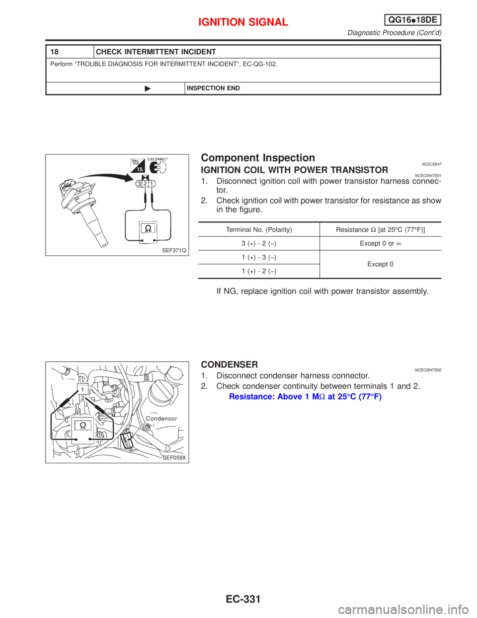
Component InspectionNCEC0547IGNITION COIL WITH POWER TRANSISTORNCEC0547S011. Disconnect ignition coil with power transistor harness connec-
tor.
2. Check ignition coil with power transistor for resistance as show
in the figure.
Terminal No. (Polarity) ResistanceW[at 25ÉC (77ÉF)]
3 (+) - 2 (þ) Except 0 or¥
1 (+) - 3 (þ)
Except 0
1 (+) - 2 (þ)
If NG, replace ignition coil with power transistor assembly.
CONDENSERNCEC0547S021. Disconnect condenser harness connector.
2. Check condenser continuity between terminals 1 and 2.
Resistance: Above 1 MWat 25ÉC (77ÉF)
SEF371Q
SEF059X
IGNITION SIGNALQG16I18DE
Diagnostic Procedure (Cont'd)
EC-331
Page 774 of 2267
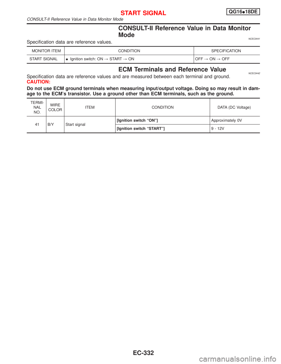
CONSULT-II Reference Value in Data Monitor
Mode
NCEC0441Specification data are reference values.
MONITOR ITEM CONDITION SPECIFICATION
START SIGNALIIgnition switch: ON,START,ON OFF,ON,OFF
ECM Terminals and Reference ValueNCEC0442Specification data are reference values and are measured between each terminal and ground.
CAUTION:
Do not use ECM ground terminals when measuring input/output voltage. Doing so may result in dam-
age to the ECM's transistor. Use a ground other than ECM terminals, such as the ground.
TERMI-
NAL
NO.WIRE
COLORITEM CONDITION DATA (DC Voltage)
41 B/Y Start signal[Ignition switch ªONº]Approximately 0V
[Ignition switch ªSTARTº]9 - 12V
START SIGNALQG16I18DE
CONSULT-II Reference Value in Data Monitor Mode
EC-332
Page 775 of 2267
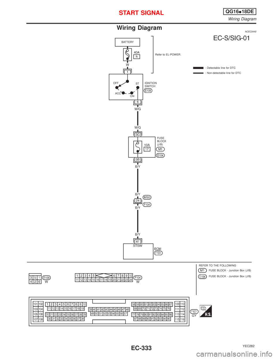
Wiring DiagramNCEC0440
YEC282
BATTERY
Refer to EL-POWER.
: Detectable line for DTC
: Non-detectable line for DTC
FUSE
BLOCK
(J/B) IGNITION
SWITCH
REFER TO THE FOLLOWING
FUSE BLOCK - Junction Box (J/B)
FUSE BLOCK - Junction Box (J/B) OFF
ACC
ONST
START SIGNALQG16I18DE
Wiring Diagram
EC-333
Page 776 of 2267
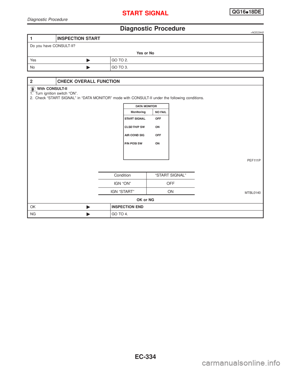
Diagnostic Procedure=NCEC0443
1 INSPECTION START
Do you have CONSULT-II?
YesorNo
Ye s©GO TO 2.
No©GO TO 3.
2 CHECK OVERALL FUNCTION
With CONSULT-II
1. Turn ignition switch ªONº.
2. Check ªSTART SIGNALº in ªDATA MONITORº mode with CONSULT-II under the following conditions.
PEF111P
MTBL0140
OK or NG
OK©INSPECTION END
NG©GO TO 4.
Condition ªSTART SIGNALº
IGN ªONº OFF
IGN ªSTARTº ON
START SIGNALQG16I18DE
Diagnostic Procedure
EC-334
Page 777 of 2267
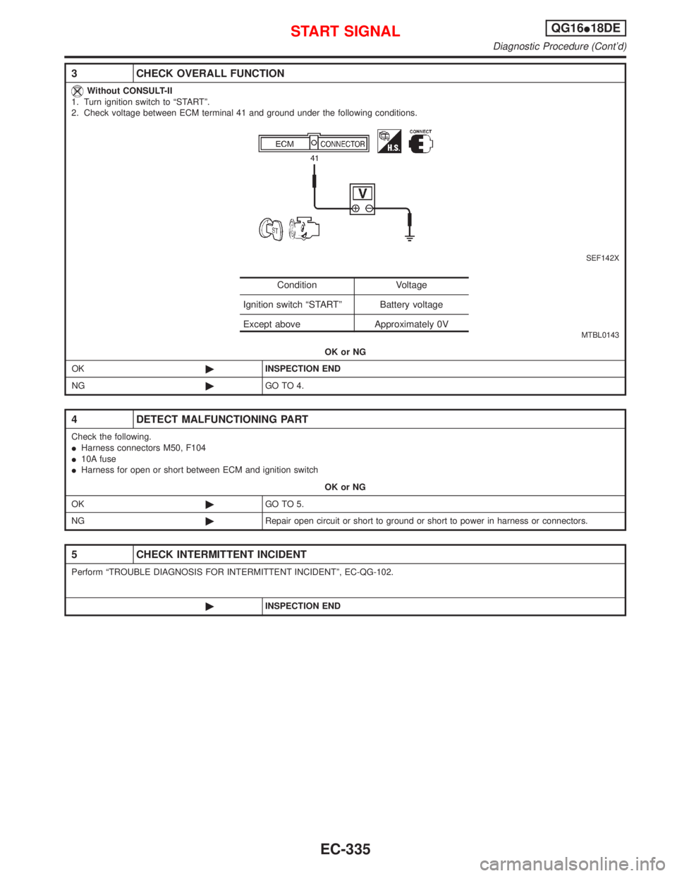
3 CHECK OVERALL FUNCTION
Without CONSULT-II
1. Turn ignition switch to ªSTARTº.
2. Check voltage between ECM terminal 41 and ground under the following conditions.
SEF142X
MTBL0143
OK or NG
OK©INSPECTION END
NG©GO TO 4.
4 DETECT MALFUNCTIONING PART
Check the following.
IHarness connectors M50, F104
I10A fuse
IHarness for open or short between ECM and ignition switch
OK or NG
OK©GO TO 5.
NG©Repair open circuit or short to ground or short to power in harness or connectors.
5 CHECK INTERMITTENT INCIDENT
Perform ªTROUBLE DIAGNOSIS FOR INTERMITTENT INCIDENTº, EC-QG-102.
©INSPECTION END
Condition Voltage
Ignition switch ªSTARTº Battery voltage
Except above Approximately 0V
START SIGNALQG16I18DE
Diagnostic Procedure (Cont'd)
EC-335
Page 778 of 2267
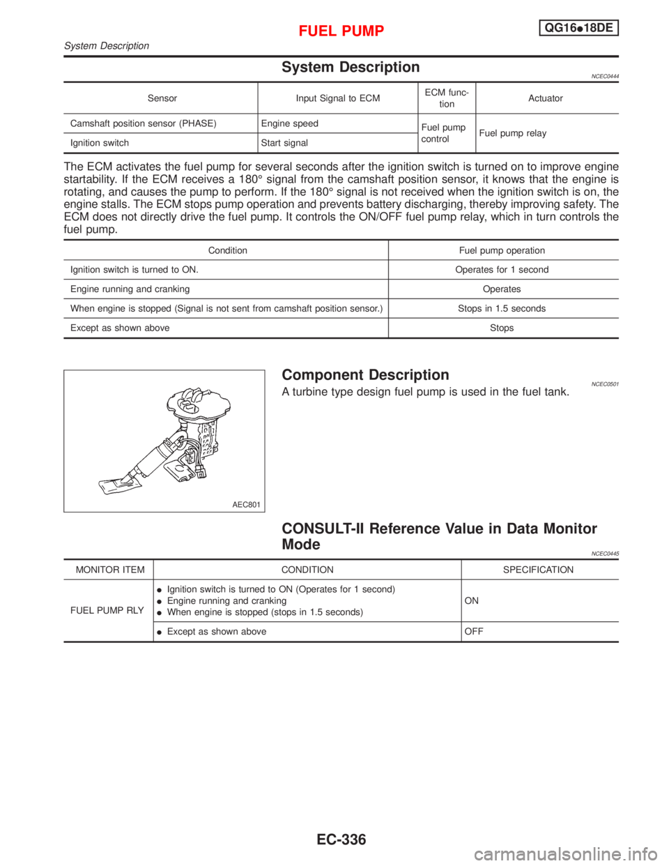
System DescriptionNCEC0444
Sensor Input Signal to ECMECM func-
tionActuator
Camshaft position sensor (PHASE) Engine speed
Fuel pump
controlFuel pump relay
Ignition switch Start signal
The ECM activates the fuel pump for several seconds after the ignition switch is turned on to improve engine
startability. If the ECM receives a 180É signal from the camshaft position sensor, it knows that the engine is
rotating, and causes the pump to perform. If the 180É signal is not received when the ignition switch is on, the
engine stalls. The ECM stops pump operation and prevents battery discharging, thereby improving safety. The
ECM does not directly drive the fuel pump. It controls the ON/OFF fuel pump relay, which in turn controls the
fuel pump.
Condition Fuel pump operation
Ignition switch is turned to ON. Operates for 1 second
Engine running and cranking Operates
When engine is stopped (Signal is not sent from camshaft position sensor.) Stops in 1.5 seconds
Except as shown aboveStops
Component DescriptionNCEC0501A turbine type design fuel pump is used in the fuel tank.
CONSULT-II Reference Value in Data Monitor
Mode
NCEC0445
MONITOR ITEM CONDITION SPECIFICATION
FUEL PUMP RLYIIgnition switch is turned to ON (Operates for 1 second)
IEngine running and cranking
IWhen engine is stopped (stops in 1.5 seconds)ON
IExcept as shown above OFF
AEC801
FUEL PUMPQG16I18DE
System Description
EC-336
Page 779 of 2267
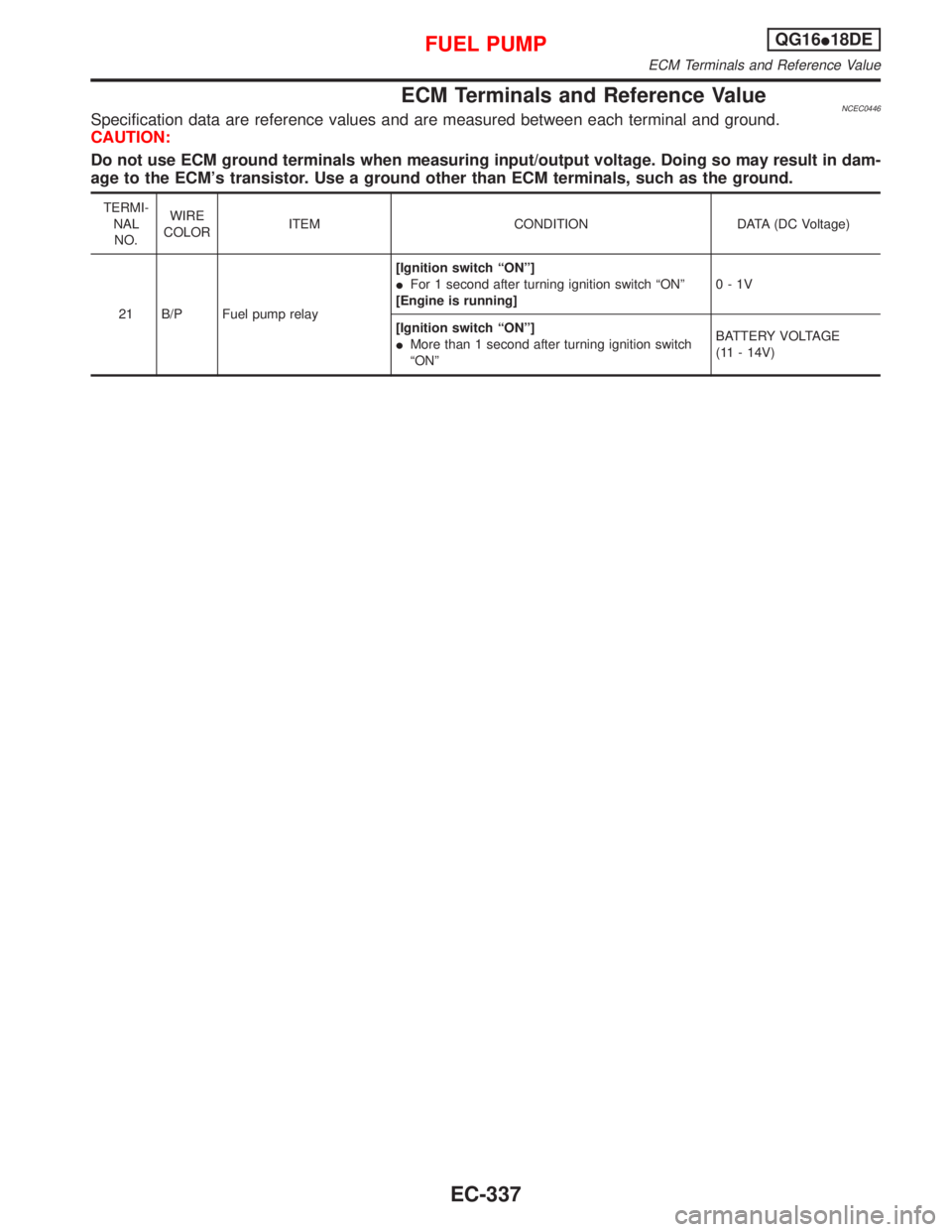
ECM Terminals and Reference ValueNCEC0446Specification data are reference values and are measured between each terminal and ground.
CAUTION:
Do not use ECM ground terminals when measuring input/output voltage. Doing so may result in dam-
age to the ECM's transistor. Use a ground other than ECM terminals, such as the ground.
TERMI-
NAL
NO.WIRE
COLORITEM CONDITION DATA (DC Voltage)
21 B/P Fuel pump relay[Ignition switch ªONº]
IFor 1 second after turning ignition switch ªONº
[Engine is running]0-1V
[Ignition switch ªONº]
IMore than 1 second after turning ignition switch
ªONºBATTERY VOLTAGE
(11 - 14V)
FUEL PUMPQG16I18DE
ECM Terminals and Reference Value
EC-337
Page 780 of 2267
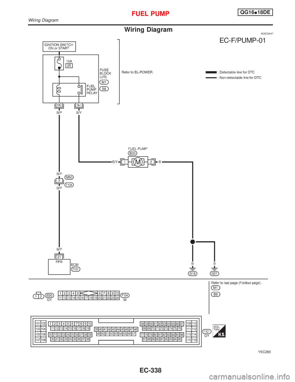
Wiring DiagramNCEC0447
YEC280
FUEL PUMPQG16I18DE
Wiring Diagram
EC-338