light NISSAN PULSAR 1987 User Guide
[x] Cancel search | Manufacturer: NISSAN, Model Year: 1987, Model line: PULSAR, Model: NISSAN PULSAR 1987Pages: 238, PDF Size: 28.91 MB
Page 33 of 238
Roadside Trouble Shooting
(5) Place the vent caps loosely over the cell
apertures.
(6) Connect one end of the red jumper lead to
the positive ( + ) battery terminal of the booster
battery and the other end of the red lead to the
positive (+) battery terminal of the discharged bat-
tery.
NOTE: The battery emits hydrogen gas
which is explosive. Do not expose the battery
to naked /lames or sparks.
Do not lean over the battery when con-
necting the jumper leads.
Do not allow the ends of the jumper leads
to touch one another or any part of the
engine.
(7) Connect one end of the black juniper lead to
the negative (-) battery terminal of the booster
battery and the other end of the black lead to a good
earthing point on the engine of the vehicle with the
discharged battery.
NOTE: Do not connect the jumper lead
directly to the negative (-) battery terminal
of the discharged battery.
(8) Start the engine on the vehicle with the
booster battery and run the engine at a moderate
speed. (9) Start the engine on the vehicle with the
discharged battery.
(10) If possible, leave the engines of both vehi-
cles running for 10 minutes.
(11) Disconnect the jumper leads in the reverse
order of the sequence in which they were connected.
2. TO CHECK IGNITION AND ELECTRICAL SYSTEM
(1) Switch on the ignition and check for warning
lamp illumination on the dashboard. (2) Operate the starter and check that the starter
rotates the engine at a steady speed.
(3) Switch on the headlamps and check for good
light intensity. Should the lamps not illum inate or the starter
motor not turn the engine, carry out the following
steps:
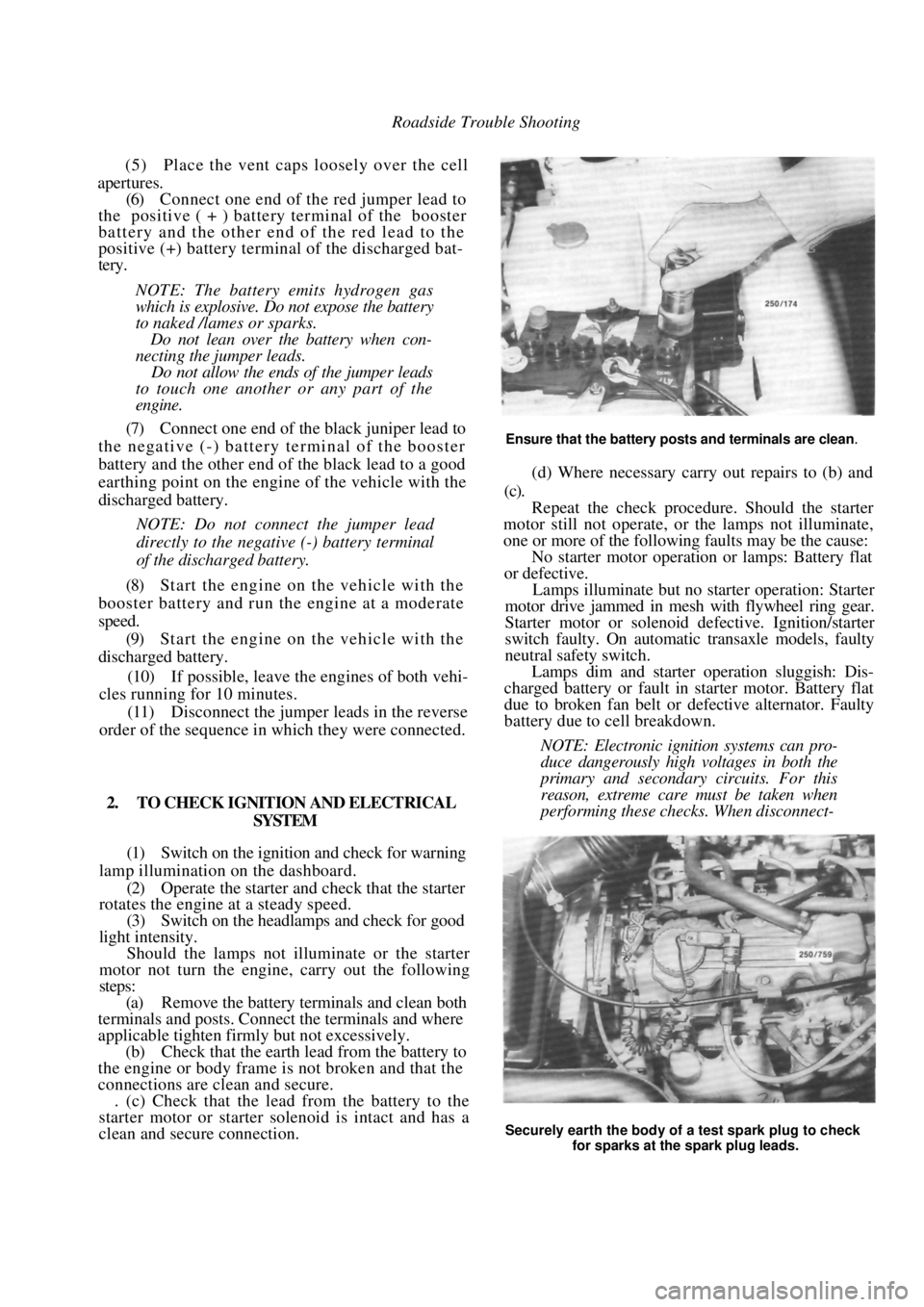
(a) Remove the battery terminals and clean both
terminals and posts. Connect the terminals and where
applicable tighten firmly but not excessively.
(b) Check that the earth lead from the battery to
the engine or body frame is not broken and that the
connections are clean and secure. . (c) Check that the lead from the battery to the
starter motor or starter solenoid is intact and has a
clean and secure connection.
Ensure that the battery posts and terminals are clean.
(d) Where necessary carry out repairs to (b) and
(c).
Repeat the check procedur e. Should the starter
motor still not operate, or the lamps not illuminate,
one or more of the following faults may be the cause:
No starter motor operation or lamps: Battery flat
or defective.
Lamps illuminate but no starter operation: Starter
motor drive jammed in mesh with flywheel ring gear.
Starter motor or solenoid defective. Ignition/starter
switch faulty. On automatic transaxle models, faulty
neutral safety switch.
Lamps dim and starter operation sluggish: Dis-
charged battery or fault in starter motor. Battery flat
due to broken fan belt or de fective alternator. Faulty
battery due to cell breakdown.
NOTE: Electronic ignition systems can pro-
duce dangerously high voltages in both the
primary and secondary circuits. For this
reason, extreme care must be taken when
performing these checks. When disconnect-
Securely earth the body of a test spark plug to check
for sparks at the spark plug leads.
Page 43 of 238
Engine 43
CAMSHAFT HOUSING TOP COVER
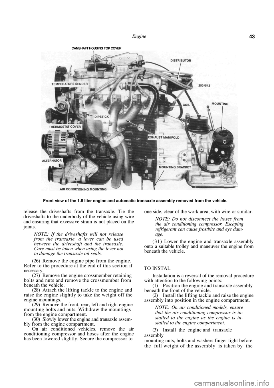
Front view of the 1.8 liter engine and automatic transaxle assembly removed from the vehicle.
release the driveshafts from the transaxle. Tie the
driveshafts to the underbody of the vehicle using wire
and ensuring that excessive st rain is not placed on the
joints.
NOTE: If the driveshafts will not release
from the transaxle, a lever can be used
between the driveshaft and the transaxle.
Care must be taken when using the lever not
to damage the transaxle oil seals.
(26) Remove the engine pipe from the engine.
Refer to the procedure at the end of this section if
necessary.
(27) Remove the engine crossmember retaining
bolts and nuts and remove the crossmember from
beneath the vehicle. (28) Attach the lifting tackle to the engine and
raise the engine slightly to take the weight off the
engine mountings. (29) Remove the front, rear, left and right engine
mounting bolts and nuts. Withdraw the mountings
from the engine compartment. (30) Slowly lower the engine and transaxle assem-
bly from the engine compartment. On air conditioned vehicles, remove the air
conditioning compressor an d hoses after the engine
has been lowered slightly. Secure the compressor to
one side, clear of the work area, with wire or similar.
NOTE: Do not disconnect the hoses from
the air conditioning compressor. Escaping
refrigerant can cause frostbite and eye dam-
age.
( 3 1 ) Lower the engine and transaxle assembly
onto a suitable trolley and maneuver the engine from
beneath the vehicle.
TO INSTAL
Installation is a reversal of the removal procedure
with attention to the following points:
(1) Position the engine and transaxle assembly
beneath the front of the vehicle.
(2) Install the lifting tackle and raise the engine
assembly into position in the engine compartment.
NOTE: On air conditioned models, ensure
that the air conditioning compressor is in-
stalled to the engine as the engine is in-
stalled to the engine compartment.
(3) Install the engine and transaxle
assembly
mounting nuts, bolts and washers finger tight before
the full weight of the assembly is taken by the
Page 44 of 238
44 Engine
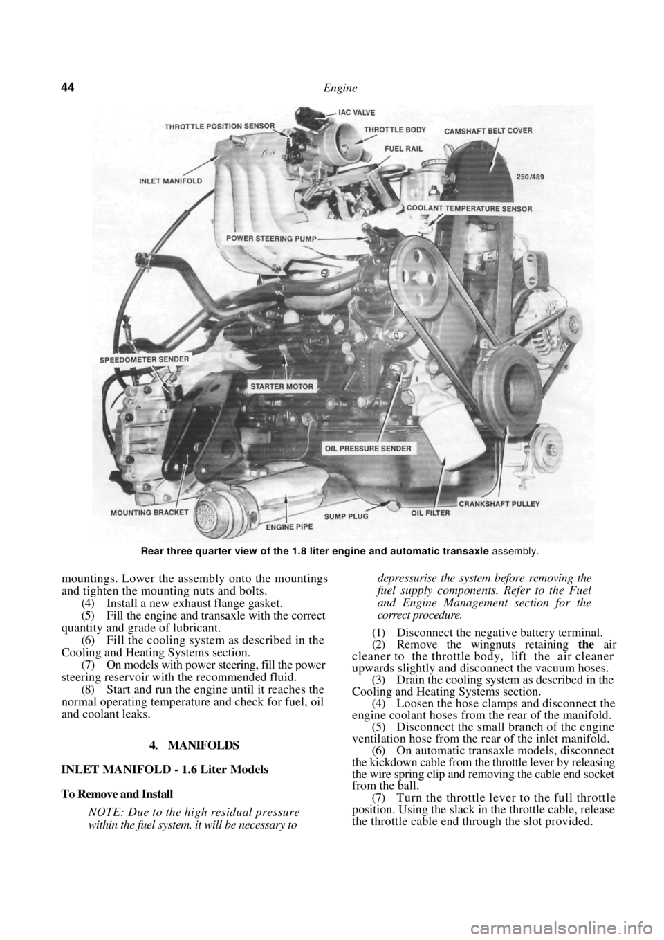
Rear three quarter view of the 1.8 liter engine and automatic transaxle assembly.
mountings. Lower the assembly onto the mountings
and tighten the mounting nuts and bolts.
(4) Install a new exhaust flange gasket.
(5) Fill the engine and transaxle with the correct
quantity and grade of lubricant. (6) Fill the cooling system as described in the
Cooling and Heating Systems section. (7) On models with power steering, fill the power
steering reservoir with the recommended fluid.
(8) Start and run the engine until it reaches the
normal operating temperatur e and check for fuel, oil
and coolant leaks.
4. MANIFOLDS
INLET MANIFOLD - 1.6 Liter Models
To Remove and Install
NOTE: Due to the high residual pressure
within the fuel system, it will be necessary to
depressurise the system before removing the
fuel supply components. Refer to the Fuel
and Engine Management section for the
correct procedure.
(1) Disconnect the negative battery terminal.
(2) Remove the wingnuts retaining the air
cleaner to the throttle body, lift the air cleaner
upwards slightly and disconnect the vacuum hoses. (3) Drain the cooling system as described in the
Cooling and Heating Systems section. (4) Loosen the hose clamps and disconnect the
engine coolant hoses from the rear of the manifold.
(5) Disconnect the small branch of the engine
ventilation hose from the rear of the inlet manifold. (6) On automatic transaxle models, disconnect
the kickdown cable from the throttle lever by releasing
the wire spring clip and re moving the cable end socket
from the ball.
(7) Turn the throttle lever to the full throttle
position. Using the slack in the throttle cable, release
the throttle cable end thr ough the slot provided.
Page 47 of 238
Engine 47
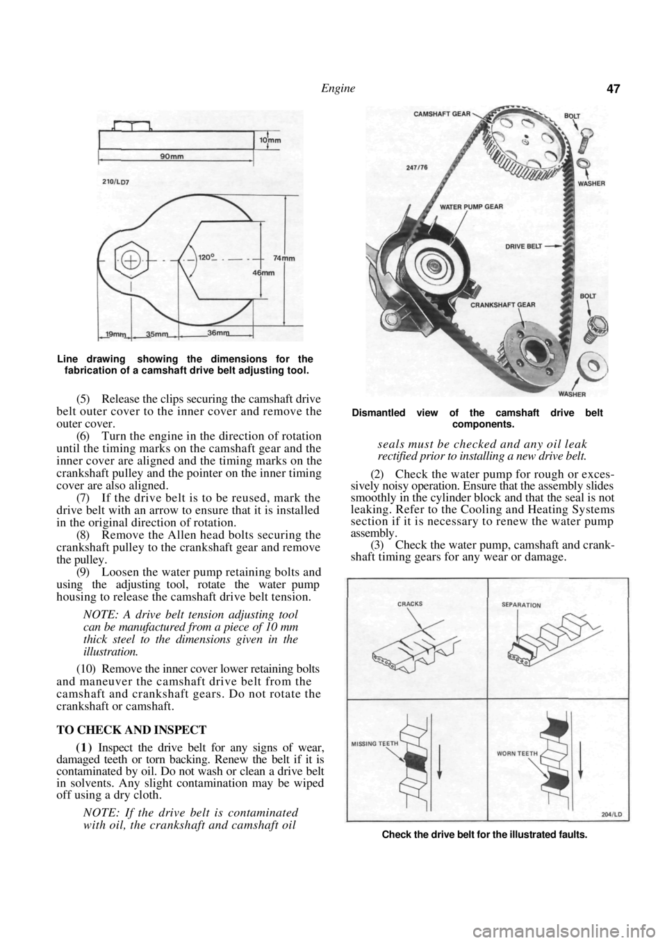
Line drawing showing the dimensions for the fabrication of a camshaft drive belt adjusting tool.
(5) Release the clips securing the camshaft drive
belt outer cover to the inner cover and remove the
outer cover.
(6) Turn the engine in the direction of rotation
until the timing marks on the camshaft gear and the
inner cover are aligned and the timing marks on the
crankshaft pulley and the pointer on the inner timing
cover are also aligned.
(7) If the drive belt is to be reused, mark the
drive belt with an arrow to ensure that it is installed
in the original direction of rotation. (8) Remove the Allen head bolts securing the
crankshaft pulley to the crankshaft gear and remove
the pulley. (9) Loosen the water pump retaining bolts and
using the adjusting tool, rotate the water pump
housing to release the camsh aft drive belt tension.
NOTE: A drive belt tension adjusting tool
can be manufactured from a piece of 10 mm
thick steel to the dimensions given in the
illustration.
(10) Remove the inner cover lower retaining bolts
and maneuver the camshaft drive belt from the
camshaft and crankshaft gears. Do not rotate the
crankshaft or camshaft.
TO CHECK AND INSPECT
(1) Inspect the drive belt for any signs of wear,
damaged teeth or torn backing. Renew the belt if it is
contaminated by oil. Do not wash or clean a drive belt
in solvents. Any slight contamination may be wiped
off using a dry cloth.
NOTE: If the drive belt is contaminated
with oil, the crankshaft and camshaft oil
Dismantled view of the camshaft drive belt
components.
seals must be checked and any oil leak
rectified prior to installing a new drive belt.
(2) Check the water pump for rough or exces-
sively noisy operation. Ensure that the assembly slides
smoothly in the cylinder bloc k and that the seal is not
leaking. Refer to the Cooling and Heating Systems
section if it is necessary to renew the water pump
assembly. (3) Check the water pump, camshaft and crank-
shaft timing gears for any wear or damage.
Check the drive belt for the illustrated faults.
Page 51 of 238
Engine 51
coolant temperature sensor and temperature sender
switch located in the thermostat housing.
(8) Remove the bolt securing the wiring clamp
to the rear of the manifold and maneuver the wiring
away from the cylinder head and the inlet manifold.
(9) Disconnect the throttle cable and on auto-
matic transaxle models, the kickdown cable from the
throttle body linkage. (10) Remove the bolls securing the throttle cable
bracket to the inlet manifold and place the bracket
and cable(s) to one side.
(11) Mark the fuel supply and return hoses to
ensure correct installation and disconnect the hoses
from the fuel rail or throttle body. Plug the hoses to
prevent the loss of fuel or the entry of dirt. (12) Mark the vacuum hoses connected to the
inlet manifold and throttle body to ensure correct
installation and disconnect the hoses. (13) Remove the nuts securing the engine pipe to
the exhaust manifold and separate the pipe from the
manifold. (14) Remove the oxygen sensor from the exhaust
manifold. Refer to the Fuel and Engine Management
section if necessary. (15) Remove the distributor and coil as described
in the Fuel and Engine Management section. (16) Disconnect the engine breather hoses from
the camshaft housing and cams haft housing top cover.
(17) Remove the bolts retaining the top cover to
the camshaft housing and remove the top cover. (18) Using an open end spanner, hold the cam-
shaft between the inlet and exhaust lobes of number
four cylinder and remove the camshaft timing gear
retaining bolt and the camshaft timing gear.
(19) Remove the bolts securing the camshaft
drive belt inner cover to the camshaft housing. (20) Loosen the cylinder head bolts in the reverse
order of the tightening sequence, backing off each bolt
a quarter turn then half a turn at a time until the bolts
are loose.
NOTE: Do not loosen the head bolts while
the engine is warm as distortion of the
cylinder head could result.
(21) Remove the cylinder head bolts and lift the
camshaft housing from the cylinder head. (22) Remove the cylinder head and gasket from
the cylinder block. Installation is a reversal of the removal procedure
with attention to the following points:
(1) Thoroughly clean the gasket surfaces of the
cylinder head, cylinder block and camshaft housing
and check all mating surfaces with a straight edge.
Ensure that all the oilways are clean and free of any
foreign material and lightly oil all operating parts with
engine oil.
(2) Install new gaskets throughout during
assem-
bly.
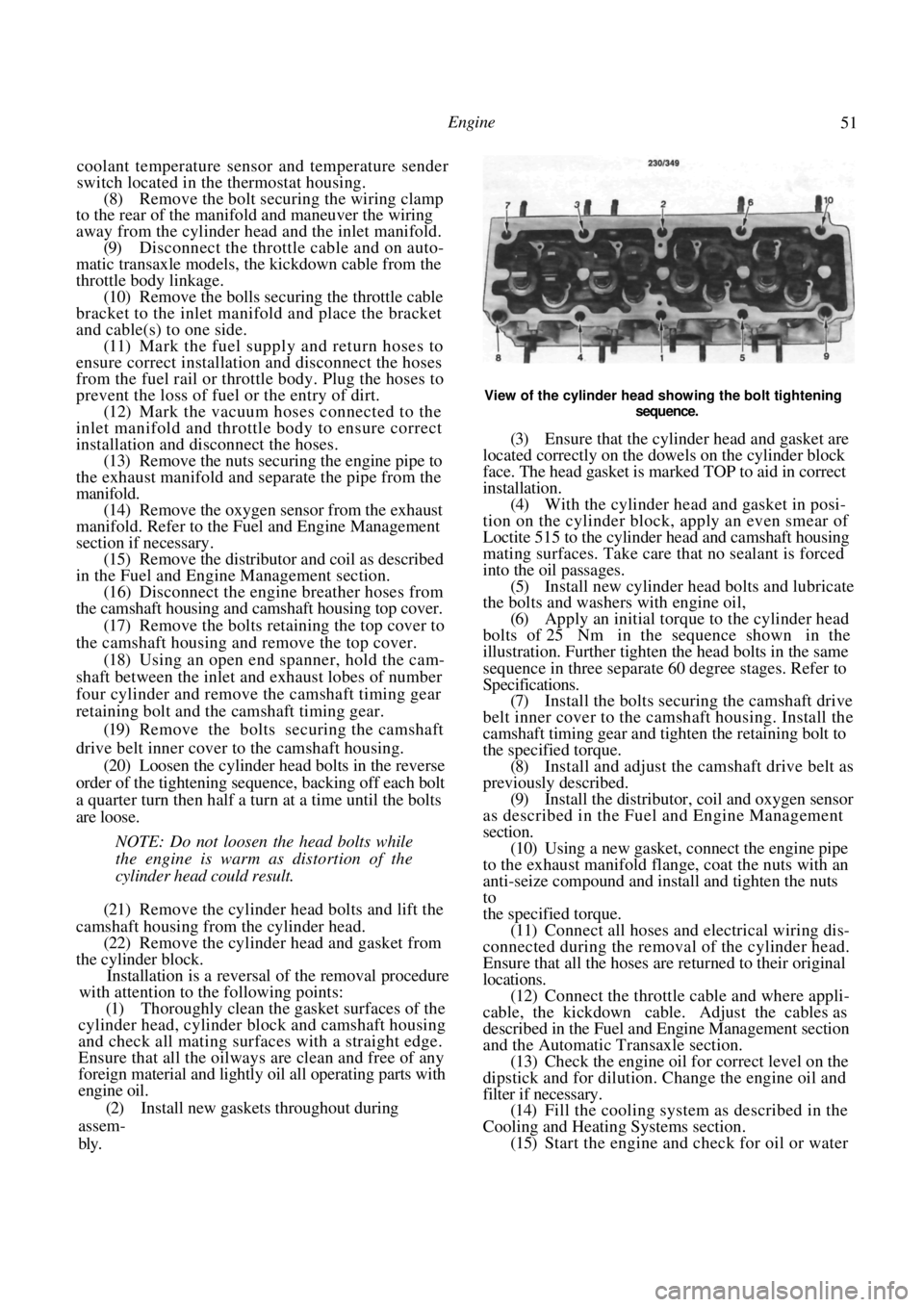
View of the cylinder head showing the bolt tightening
sequence.
(3) Ensure that the cylinde r head and gasket are
located correctly on the dowels on the cylinder block
face. The head gasket is marked TOP to aid in correct
installation. (4) With the cylinder head and gasket in posi-
tion on the cylinder block, apply an even smear of
Loctite 515 to the cylinder head and camshaft housing
mating surfaces. Take care that no sealant is forced
into the oil passages. (5) Install new cylinder head bolts and lubricate
the bolts and washers with engine oil,
(6) Apply an initial torque to the cylinder head
bolts of 25 Nm in the sequence shown in the
illustration. Further tighten the head bolts in the same
sequence in three separate 60 degree stages. Refer to
Specifications. (7) Install the bolts secur ing the camshaft drive
belt inner cover to the camshaft housing. Install the
camshaft timing gear and tighten the retaining bolt to
the specified torque. (8) Install and adjust the camshaft drive belt as
previously described. (9) Install the distributor, coil and oxygen sensor
as described in the Fuel and Engine Management
section.
(10) Using a new gasket, connect the engine pipe
to the exhaust manifold flange, coat the nuts with an
anti-seize compound and install and tighten the nuts
to
the specified torque. (11) Connect all hoses and electrical wiring dis-
connected during the removal of the cylinder head.
Ensure that all the hoses are returned to their original
locations. (12) Connect the throttle cable and where appli-
cable, the kickdown cable. Adjust the cables as
described in the Fuel and Engine Management section
and the Automatic Transaxle section. (13) Check the engine oil fo r correct level on the
dipstick and for dilution. Change the engine oil and
filter if necessary. (14) Fill the cooling system as described in the
Cooling and Heating Systems section. (15) Start the engine and check for oil or water
Page 56 of 238
56 Engine
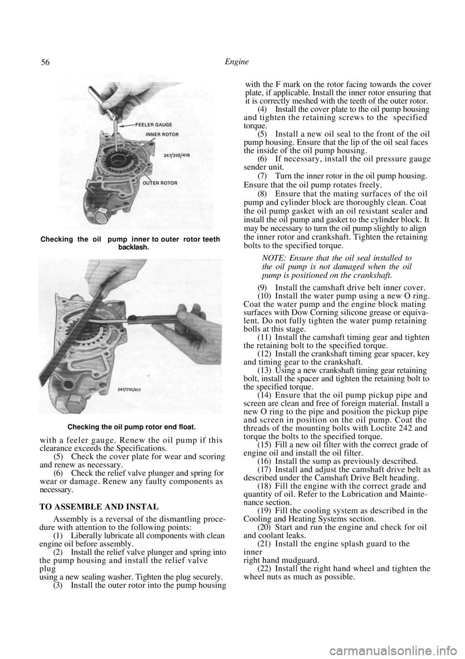
Checking the oil pump rotor end float.
with a feeler gauge. Renew the oil pump if this
clearance exceeds the Specifications.
(5) Check the cover plate for wear and scoring
and renew as necessary. (6) Check the relief valve plunger and spring for
wear or damage. Renew any faulty components as
necessary.
TO ASSEMBLE AND INSTAL
Assembly is a reversal of the dismantling proce-
dure with attention to the following points:
(1) Liberally lubricate all components with clean
engine oil before assembly. (2) Install the relief valve plunger and spring into
the pump housing and install the relief valve
plug
using a new sealing washer. Tighten the plug securely. (3) Install the outer rotor into the pump housing with the F mark on the rotor facing towards the cover
plate, if applicable. Install the inner rotor ensuring that
it is correctly meshed with the teeth of the outer rotor.
(4)
Install the cover plate to the oil pump housing
and tighten the retaining screws to the specified
torque. (5) Install a new oil seal to the front of the oil
pump housing. Ensure that the lip of the oil seal faces
the inside of the oil pump housing. (6) If necessary, install the oil pressure gauge
sender unit.
(7) Turn the inner rotor in the oil pump housing.
Ensure that the oil pump rotates freely. (8) Ensure that the mating surfaces of the oil
pump and cylinder block are thoroughly clean. Coat
the oil pump gasket with an oil resistant sealer and
install the oil pump and gasket to the cylinder block. It
may be necessary to turn the oil pump slightly to align
the inner rotor and crankshaft. Tighten the retaining
bolts to the specified torque.
NOTE: Ensure that the oil seal installed to
the oil pump is not damaged when the oil
pump is positioned on the crankshaft.
(9) Install the camshaft drive belt inner cover.
(10) Install the water pump using a new O ring.
Coat the water pump and the engine block mating
surfaces with Dow Corning silicone grease or equiva-
lent. Do not fully tighten the water pump retaining
bolls at this stage. (11) Install the camshaft timing gear and tighten
the retaining bolt to the specified torque.
(12) Install the crankshaft timing gear spacer, key
and timing gear to the crankshaft. (13) Using a new crankshaft timing gear retaining
bolt, install the spacer and tighten the retaining bolt to
the specified torque. (14) Ensure that the oil pump pickup pipe and
screen are clean and free of foreign material. Install a
new O ring to the pipe and position the pickup pipe
and screen in position on the oil pump. Coat the
threads of the mounting bolts with Loctite 242 and
torque the bolts to the specified torque. (15) Fill a new oil filter with the correct grade of
engine oil and install the oil filter. (16) Install the sump as previously described.
(17) Install and adjust the camshaft drive belt as
described under the Camshaft Drive Belt heading. (18) Fill the engine with the correct grade and
quantity of oil. Refer to the Lubrication and Mainte-
nance section.
(19) Fill the cooling system as described in the
Cooling and Heating Systems section. (20) Start and run the engine and check for oil
and coolant leaks. (21) Install the engine splash guard to the
inner
right hand mudguard. (22) Install the right hand wheel and tighten the
wheel nuts as much as possible.
Checking the oil pump inner to outer rotor teeth
backlash.
Page 61 of 238
Engine 61
rear main bearing cap and engine block. Discard the
oil seal.
(3) Ensure that all main bearing and connecting
rod bearing caps are numbered to ensure correct
assembly. (4) Remove the connecting rod bolts and caps,
keeping them in order. Push each piston and connect-
ing rod slightly up into the bore without pushing the
piston beyond its upper limit. (5) Check the crankshaft end float by inserting a
feeler gauge between the shaft and the centre main
bearing, or by mounting a dial gauge with its plunger
against one end of the shaft. (6) Push the crankshaft into contact with the
front edge of the centre main bearing, then lever the
shaft forward to determine the end float.
(7) If the end float exceeds the Specifications,
renew the centre main bearing on assembly. (8) Check the main bearing clearance by the
Plastigage method as follows:
(a) Remove one bearing cap and with a piece of
rag wipe the journal and bearing clean.
(b) Position a piece of Plastigage, the approxi-
mate length of the bearing width and slightly off
centre, on the bearing surface of the crankshaft
journal. (c) Install the bearing ca p and tighten the cap
bolts to the specified torque.
NOTE: Do not rotate the crankshaft while
the Plastigage is in position.
(d) Remove the cap bolts and carefully detach
the cap and lower half bearing. (e) With the Plastigage scal e, measure the com-
pressed Plastigage strip to determine the clearance. (f) The widest point of the strip will indicate the
minimum clearance and th e narrowest point the
maximum clearance. (g) The remaining bearings can be checked in
turn using the same procedure.
(9) Lift the crankshaft from the crankcase using
care not to dislodge or damage the upper halves of the
main bearing shells if they are to be used again. (10) If new bearing shells are to be installed,
remove the upper halves of the bearings from the
crankcase.
TO CHECK AND INSPECT
After thoroughly cleaning the crankshaft in sol-
vent and drying it with co mpressed air, blow out all
the oilways and make the following checks:
(1) Check and measure the main bearing jour-
nals and crankpins for wear, taper and scoring. If wear
is excessive, the journals and/or crankpins should be
ground to accommodate the nearest underside bearing
shells.
One worn or damaged journal or crankpin will
necessitate the grinding of all the journals or crank-
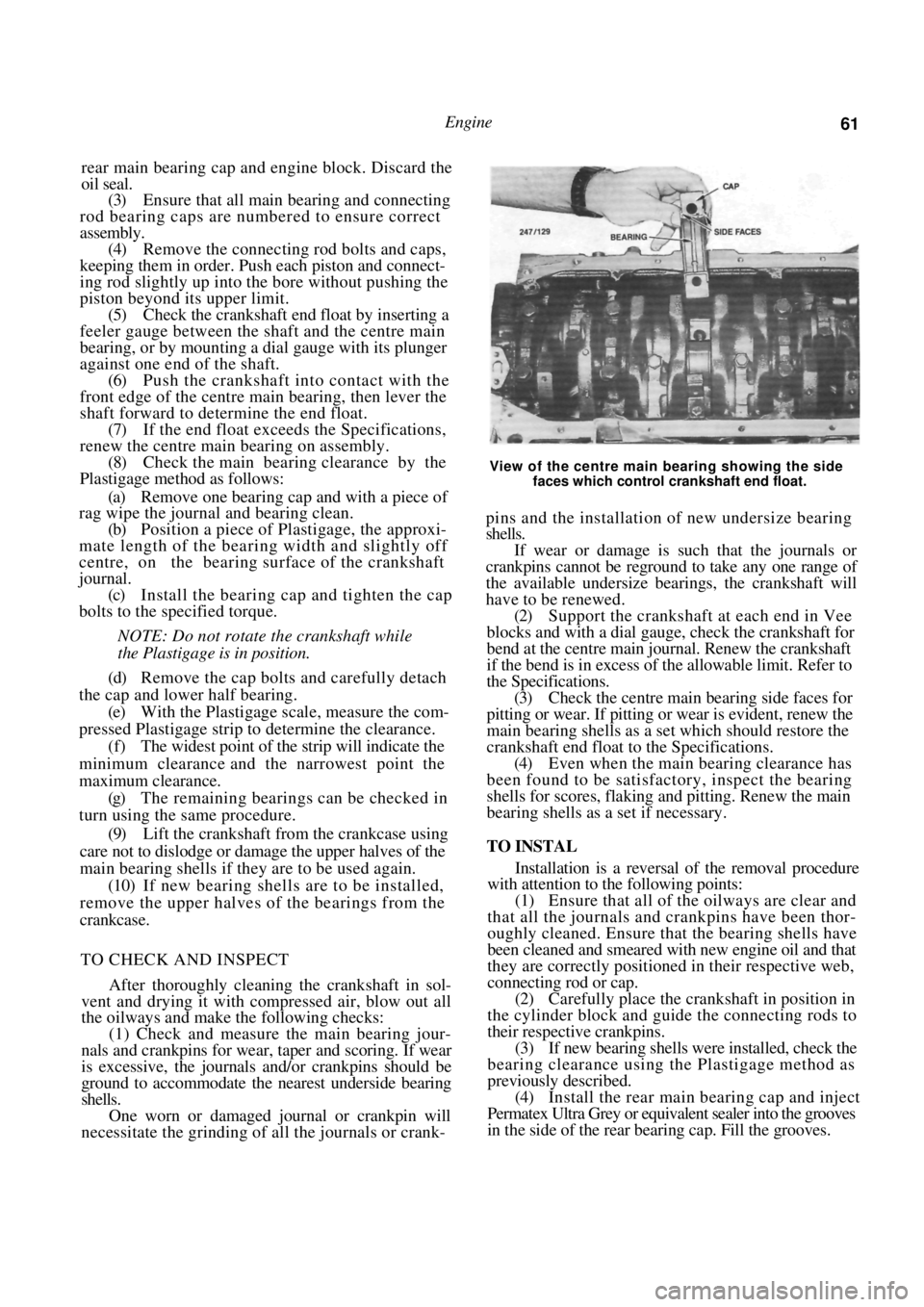
View of the centre main bearing showing the side
faces which control crankshaft end float.
pins and the installation of new undersize bearing
shells.
If wear or damage is such that the journals or
crankpins cannot be reground to take any one range of
the available undersize bearings, the crankshaft will
have to be renewed.
(2) Support the crankshaft at each end in Vee
blocks and with a dial gauge, check the crankshaft for
bend at the centre main jour nal. Renew the crankshaft
if the bend is in excess of the allowable limit. Refer to
the Specifications.
(3) Check the centre main bearing side faces for
pitting or wear. If pitting or wear is evident, renew the
main bearing shells as a set which should restore the
crankshaft end float to the Specifications. (4) Even when the main bearing clearance has
been found to be satisfact ory, inspect the bearing
shells for scores, flaking and pitting. Renew the main
bearing shells as a set if necessary.
TO INSTAL
Installation is a reversal of the removal procedure
with attention to the following points:
(1) Ensure that all of the oilways are clear and
that all the journals and crankpins have been thor-
oughly cleaned. Ensure that the bearing shells have
been cleaned and smeared with new engine oil and that
they are correctly positioned in their respective web,
connecting rod or cap. (2) Carefully place the crankshaft in position in
the cylinder block and guide the connecting rods to
their respective crankpins.
(3) If new bearing shells were installed, check the
bearing clearance using the Plastigage method as
previously described. (4) Install the rear main bearing cap and inject
Permatex Ultra Grey or equivalent sealer into the grooves
in the side of the rear bearing cap. Fill the grooves.
Page 62 of 238
Engine
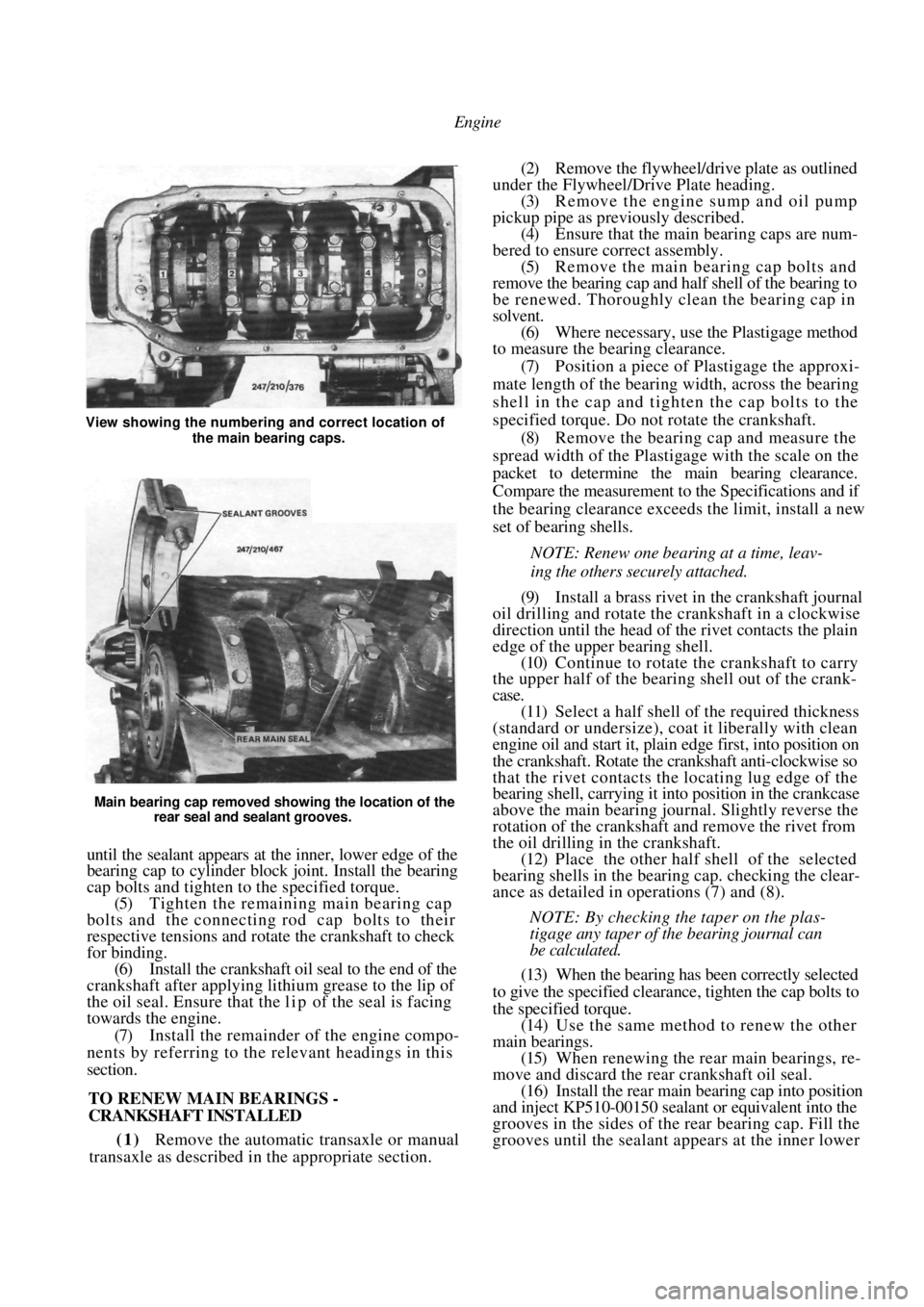
Main bearing cap removed showing the location of the rear seal and sealant grooves.
until the sealant appears at the inner, lower edge of the
bearing cap to cylinder block joint. Install the bearing
cap bolts and tighten to the specified torque.
(5) Tighten the remaining main bearing cap
bolts and the connecting rod cap bolts to their
respective tensions and rotate the crankshaft to check
for binding. (6) Install the crankshaft oil seal to the end of the
crankshaft after applying lithium grease to the lip of
the oil seal. Ensure that the l i p of the seal is facing
towards the engine.
(7) Install the remainder of the engine compo-
nents by referring to the relevant headings in this
section.
TO RENEW MAIN BEARINGS -
CRANKSHAFT INSTALLED
(1) Remove the automatic transaxle or manual
transaxle as described in the appropriate section.
(2) Remove the flywheel/drive plate as outlined
under the Flywheel/Drive Plate heading. (3) Remove the engine sump and oil pump
pickup pipe as previously described. (4) Ensure that the main bearing caps are num-
bered to ensure correct assembly. (5) Remove the main bearing cap bolts and
remove the bearing cap and half shell of the bearing to
be renewed. Thoroughly clean the bearing cap in
solvent. (6) Where necessary, use the Plastigage method
to measure the bearing clearance.
(7) Position a piece of Plastigage the approxi-
mate length of the bearing width, across the bearing
shell in the cap and tigh ten the cap bolts to the
specified torque. Do not rotate the crankshaft. (8) Remove the bearing cap and measure the
spread width of the Plastigage with the scale on the
packet to determine the main bearing clearance.
Compare the measurement to the Specifications and if
the bearing clearance exceeds the limit, install a new
set of bearing shells.
NOTE: Renew one bearing at a time, leav-
ing the others securely attached.
(9) Install a brass rivet in the crankshaft journal
oil drilling and rotate the crankshaft in a clockwise
direction until the head of the rivet contacts the plain
edge of the upper bearing shell. (10) Continue to rotate the crankshaft to carry
the upper half of the bearing shell out of the crank-
case.
(11) Select a half shell of the required thickness
(standard or undersize), coat it liberally with clean
engine oil and start it, plai n edge first, into position on
the crankshaft. Rotate the crankshaft anti-clockwise so
that the rivet contacts the locating lug edge of the
bearing shell, carrying it into position in the crankcase
above the main bearing journal. Slightly reverse the
rotation of the crankshaft and remove the rivet from
the oil drilling in the crankshaft. (12) Place the other half shell of the selected
bearing shells in the bear ing cap. checking the clear-
ance as detailed in operations (7) and (8).
NOTE: By checking the taper on the plas-
tigage any taper of the bearing journal can
be calculated.
(13) When the bearing has been correctly selected
to give the specified clearance, tighten the cap bolts to
the specified torque. (14) Use the same method to renew the other
main bearings. (15) When renewing the rear main bearings, re-
move and discard the rear crankshaft oil seal. (16) Install the rear main bearing cap into position
and inject KP510-00150 sealant or equivalent into the
grooves in the sides of the rear bearing cap. Fill the
grooves until the sealant a ppears at the inner lower
View showing the numbering and correct location of
the main bearing caps.
Page 65 of 238
Engine 65
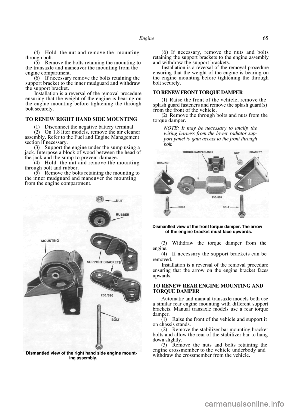
(4) Hold the nut and remove the mounting
through bolt. (5) Remove the bolts retaining the mounting to
the transaxle and maneuver the mounting from the
engine compartment. (6) If necessary remove the bolts retaining the
support bracket to the inner mudguard and withdraw
the support bracket. Installation is a reversal of the removal procedure
ensuring that the weight of the engine is bearing on
the engine mounting before tightening the through
bolt securely.
TO RENEW RIGHT HAND SIDE MOUNTING
(1) Disconnect the negative battery terminal.
(2) On 1.8 liter models, remove the air cleaner
assembly. Refer to the Fuel and Engine Management
section if necessary. (3) Support the engine under the sump using a
jack. Interpose a block of wood between the head of
the jack and the sump to prevent damage.
(4) Hold the nut and remove the mounting
through bolt and rubber. (5) Remove the bolts retain ing the mounting to
the inner mudguard and maneuver the mounting
from the engine compartment. (6) If necessary, remove the nuts and bolts
retaining the support brackets to the engine assembly
and withdraw the support brackets.
Installation is a reversal of the removal procedure
ensuring that the weight of the engine is bearing on
the engine mounting before tightening the through
bolt securely.
TO RENEW FRONT TORQUE DAMPER
(1) Raise the front of the vehicle, remove the
splash guard fasteners and remove the splash guard(s)
from the front of the vehicle.
(2) Remove the through bolts and nuts from the
torque damper.
NOTE: It may be necessary to unclip the
wiring harness from the lower radiator sup-
port panel to gain access to the front through
bolt.
Dismantled view of the front torque damper. The arrow of the engine bracket must face upwards.
(3) Withdraw the torque damper from the
engine.
(4) If necessary the support brackets can be
removed. Installation is a reversal of the removal procedure
ensuring that the arrow on the engine bracket faces
upwards.
TO RENEW REAR ENGINE MOUNTING AND
TORQUE DAMPER
Automatic and manual transaxle models both use
a similar rear engine moun ting with different support
brackets. Manual transaxle models use a rear torque
damper.
(1) Raise the front of the vehicle and support it
on chassis stands. (2) Remove the stabilizer bar mounting bracket
bolts and allow the rear of the stabilizer bar to hang
down slightly. (3) Remove the nuts and bolts retaining the
engine crossmember to the vehicle underbody and
withdraw the crossmember from the vehicle.
Dismantled view of the right hand side engine mount-
ing assembly.
Page 72 of 238
72 Cooling and Heating Systems
(16) After the vehicle has been driven several
kilometers check the coolant level in the reserve tank
and top up if necessary.
TO REMOVE
(1) Drain the cooling system as previously de-
scribed.
(2) Loosen the hose clamps and disconnect the
hoses from the radiator. (3) If applicable disconnect the automatic trans-
axle oil cooler hoses from the left hand side radiator
tank. Plug the hoses and fitt ings to prevent the entry
of dirt and the loss of fluid.
(4) Disconnect the hose from the reserve tank at
the top of the radiator. (5) On models with air conditioning, remove the
hoses and support bracket bolts and move the bracket
and hoses away from the top of the radiator. (6) Remove the radiator support bracket bolts
from the radiator support pa nel and lift the radiator
from the lower mountings and out of the vehicle.
NOTE: A radiator that has been in use for
some time should not be allowed to stand
empty for any length of time. The radiator
should be immersed in a tank of coolant or
otherwise kept full. If applicable, ensure that
no coolant is allowed to enter the automatic
transaxle oil cooler in the left hand side tank
of the radiator.
Failure to observe this precaution may
result in overheating when the engine is put
back into service. This is caused by internal
deposits in the radiator drying and flaking
and so obstructing the circulation of the
coolant in the system.
TO FLUSH AND CLEAN
(1) Remove the radiator as previously described.
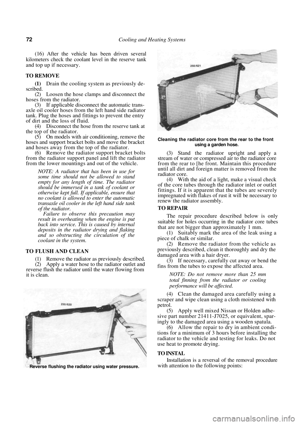
(2) Apply a water hose to the radiator outlet and
reverse flush the radiator until the water flowing from
it is clean.
Cleaning the radiator core from the rear to the front
using a garden hose.
(3) Stand the radiator upright and apply a
stream of water or compressed air to the radiator core
from the rear to [he front. Maintain this procedure
until all dirt and foreign matter is removed from the
radiator core.
(4) With the aid of a light, make a visual check
of the core tubes through the radiator inlet or outlet
fittings. If it is apparent that the tubes are severely
impregnated with flakes of rust it will be necessary to
renew the radiator assembly.
TO REPAIR
The repair procedure described below is only
suitable for holes occurring in the radiator core tubes
that are not bigger than approximately 1 mm.
(1) Suitably mark the area of the leak using a
piece of chalk or similar. (2) Remove the radiator from the vehicle as
previously described, clean it thoroughly and dry the
damaged area with a hair dryer. (3) If necessary, carefully cut away or bend the
fins from the tubes to expose the affected area.
NOTE: Do not remove more than 25 mm
total finning from the radiator or cooling
performance will be affected.
(4) Clean the damaged area carefully using a
scraper and wipe clean using a cloth moistened with
petrol.
(5) Apply well mixed Nissan or Holden adhe-
sive part number 21411-J7025, or equivalent, spar-
ingly to the damaged area using a wooden spatula.
(6) Allow the repair to dry in ambient condi-
tions for a minimum of 3 hours before installing the
radiator to the vehicle and testing for leaks. Do not
use heat to promote drying.
TO INSTAL
Installation is a reversal of the removal procedure
with attention to the following points:
Reverse flushing the radiator using water pressure.