NISSAN PULSAR 1987 Owner's Manual
Manufacturer: NISSAN, Model Year: 1987, Model line: PULSAR, Model: NISSAN PULSAR 1987Pages: 238, PDF Size: 28.91 MB
Page 21 of 238
WHEELS AND TYRES
SPECIFICATIONS
TYRES PRESSURES
Front:
Normal load ............................................ 200 kPa
Heavy load or high speed ......................230 kPa
Rear:
Normal load............................................ 180 kPa
Heavy load or high speed ...................... 210 kPa
NOTE: The above pressures are measured
cold and are meant as a guide only. Always
refer to the tire placard positioned on the
inside of the glove compartment lid and the
tire manufacturers recommendations first.
TORQUE WRENCH SETTINGS
Wheel nut torque .............................................98 Nm
1. HOW TO CHANGE A ROAD WHEEL
(1) Ensure that the vehicle is on level firm
ground and clear of any passing traffic. (2) If necessary, switch on the hazard
flashers.
(3) Switch off the engine a nd place the transaxle
in the (P) Park position on automatic transaxle
models or in reverse gear on manual transaxle models.
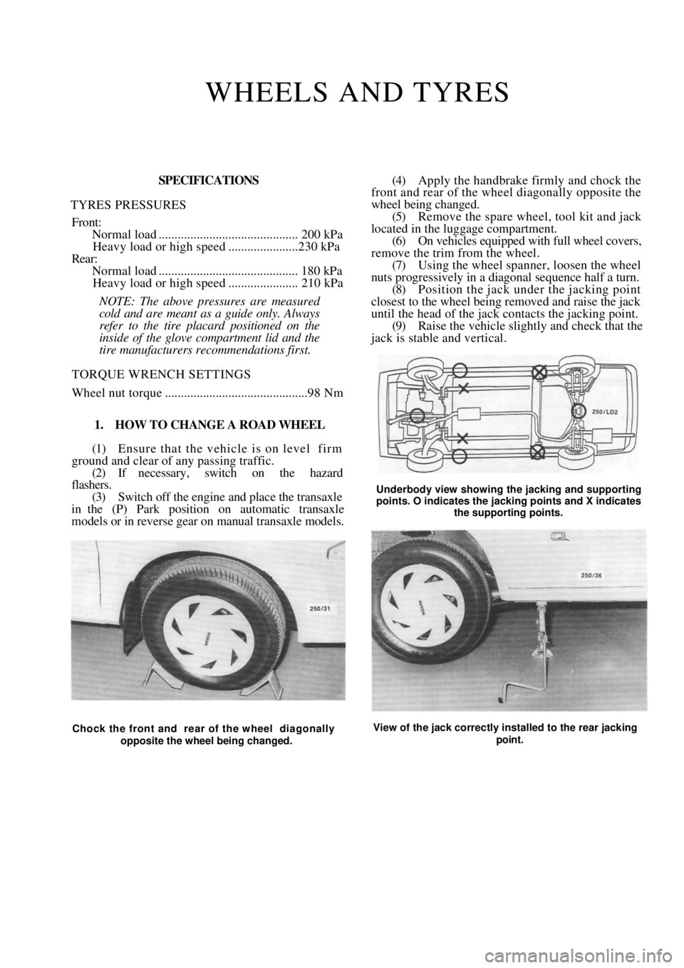
(4) Apply the handbrake firmly and chock the
front and rear of the wheel diagonally opposite the
wheel being changed.
(5) Remove the spare wheel, tool kit and jack
located in the luggage compartment. (6) On vehicles equipped with full wheel covers,
remove the trim from the wheel. (7) Using the wheel spanner, loosen the wheel
nuts progressively in a diagonal sequence half a turn.
(8) Position the jack und er the jacking point
closest to the wheel being removed and raise the jack
until the head of the jack contacts the jacking point.
(9) Raise the vehicle slightly and check that the
jack is stable and vertical.
Underbody view showing the jacking and supporting
points. O indicates the jacking points and X indicates
the supporting points.
Chock the front and rear of the wheel diagonally
opposite the wheel being changed. View of the jack correctly installed to the rear jacking
point.
Page 22 of 238
22 Wheels and Tires
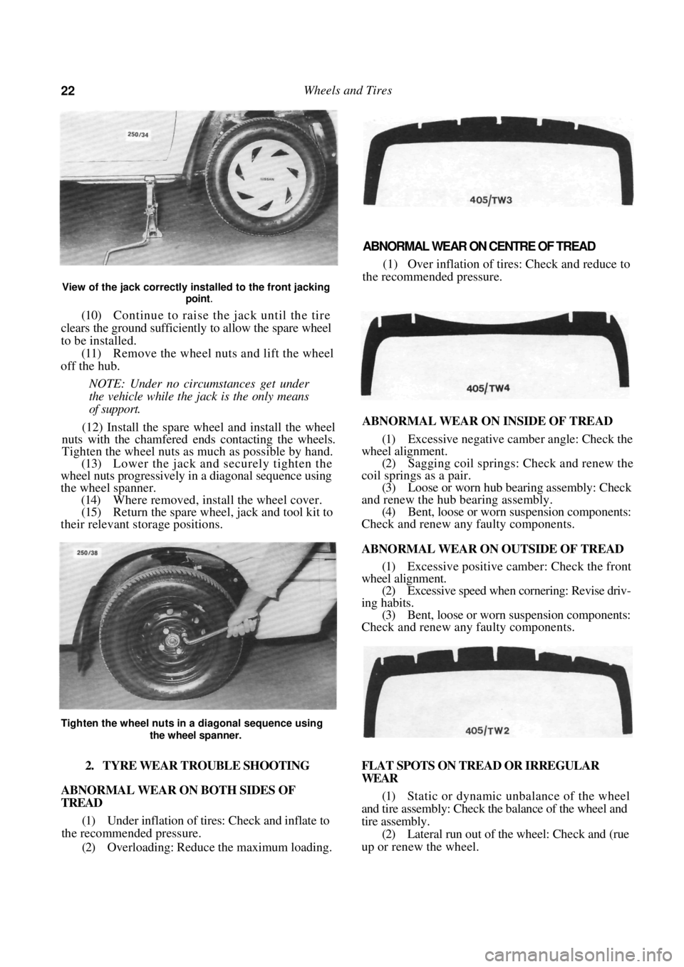
View of the jack correctly installed to the front jacking point
.
(10) Continue to raise the jack until the tire
clears the ground sufficiently to allow the spare wheel
to be installed.
(11) Remove the wheel nuts and lift the wheel
off the hub.
NOTE: Under no circumstances get under
the vehicle while the jack is the only means
of support.
(12) Install the spare wh eel and install the wheel
nuts with the chamfered e nds contacting the wheels.
Tighten the wheel nuts as much as possible by hand.
(13) Lower the jack and securely tighten the
wheel nuts progressively in a diagonal sequence using
the wheel spanner. (14) Where removed, install the wheel cover.
(15) Return the spare wheel, jack and tool kit to
their relevant storage positions.
ABNORMAL WEAR ON CENTRE OF TREAD
(1) Over inflation of tires: Check and reduce to
the recommended pressure.
ABNORMAL WEAR ON INSIDE OF TREAD
(1) Excessive negative camber angle: Check the
wheel alignment. (2) Sagging coil springs: Check and renew the
coil springs as a pair. (3) Loose or worn hub bearing assembly: Check
and renew the hub bearing assembly. (4) Bent, loose or worn suspension components:
Check and renew any faulty components.
ABNORMAL WEAR ON OUTSIDE OF TREAD
(1) Excessive positive camber: Check the front
wheel alignment.
(2) Excessive speed when cornering: Revise driv-
ing habits. (3) Bent, loose or worn suspension components:
Check and renew any faulty components.
2. TYRE WEAR TROUBLE SHOOTING
ABNORMAL WEAR ON BOTH SIDES OF
TREAD
(1) Under inflation of tires: Check and inflate to
the recommended pressure.
(2) Overloading: Reduce the maximum loading. FLAT SPOTS ON TREAD OR IRREGULAR
WEAR
(1)
Static or dynamic unbalance of the wheel
and tire assembly: Check the balance of the wheel and
tire assembly. (2) Lateral run out of the wheel: Check and (rue
up or renew the wheel.
Tighten the wheel nuts in a diagonal sequence using
the wheel spanner.
Page 23 of 238
Wheels and Tires 23
(3) Excessive play in the front suspension ball
joints: Check and renew the ball joints.
(4) Excessive play in the hub bearing assembly:
Check and renew the hub bearing assembly.
WORN SPOTS ON CENTRE OF TREAD
(1) Static unbalance of the wheel and tire asem-
bly: Check the balance of the wheel and tire assembly
(2) Radial run out (eccentricity) of the wheel:
Check and renew the wheel.
FEATHERED EDGES ON TREAD PATTERN
(1) Excessive speed when cornering: Revise driv-
ing habits. (2) Excessive toe-in or toe-out: Check and adjust
the wheel alignment.
(3) Bent, loose or worn suspension components:
Check and renew any faulty components.
NOTE: To preserve tire life it is good policy
to periodically have the front wheel balanced
and the steering geometry checked on a
reliable wheel alignment machine.
Under no circumstances mix radial ply
and conventional ply tire s. Install only tires
of the same construction to all four wheels.
3. CARE AND MAINTENANCE
STEEL WHEELS
Steel wheels should be regularly cleaned of all
foreign matter, such as dirt and mud. If foreign matter
is allowed to build up it will affect the balance of the
wheel and may cause vibrations and uneven tire wear.
If the paint has been chipped or scratched it should be
touched up as soon as possible to prevent rust.
Any minor damage to the wheel rim can usually
be repaired using a suitable hammer after the wheel
has been removed from the vehicle. However, any
major rim damage or buckling of the wheel will
necessitate the renewal of the wheel. It is good policy
to occasionally remove the wheels from the vehicle
and inspect them for damage, cracks or corrosion.
ALLOY WHEELS
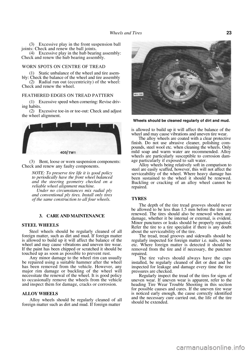
Alloy wheels should be regularly cleaned of all
foreign matter such as dirt and mud. If foreign matter
Wheels should be cleaned regularly of dirt and mud.
is allowed to build up it will affect the balance of the
wheel and may cause vibrations and uneven tire wear.
The alloy wheels are coated with a clear protective
finish. Do not use abrasive cleaner, polishing com-
pounds, steel wool etc. when cleaning the wheels. Only
mild soap and warm wate r are recommended. Alloy
wheels are particularly su sceptible to corrosion dam-
age particularly if exposed to salt water.
Alloy wheels being relatively soft in comparison to
steel are easily scuffed, however, this will not affect the
serviceability of the wheel. Where heavy damage has
been sustained to the wheel it should be renewed.
Buckling or cracking of an alloy wheel cannot be
repaired.
TYRES
The depth of the tire tread grooves should never
be allowed to be less than 1.5 mm before the tires are
renewed. The tires should also be renewed when any
damage, whether it be internal or external, is evident.
Minor punctures or leaks s hould be properly repaired.
Refer the tire to a tire spec ialist if there is any doubt
about the serviceability of the tire.
The tread, tread grooves and sidewalls should be
regularly inspected for foreign matter i.e. nails, stones
etc. Where foreign matter is detected it should be
removed from the tire and if necessary, the puncture
repaired.
The tire valves should always have the caps
installed, be regularly cleaned of dirt or dust and be
inspected for leakage and damage every time the tire
pressures are checked.
Regularly inspect the tread of the tires for signs of
uneven wear. If uneven wear is apparent, refer to the
heading Tire Wear Trouble Shooting in this section
for possible causes and cures. If the uneven tire wear
is noticed early enough, the cause correctly identified
and the necessary cure carried out, the life of the tire
should be extended.
Page 24 of 238
24 Wheels and Tires
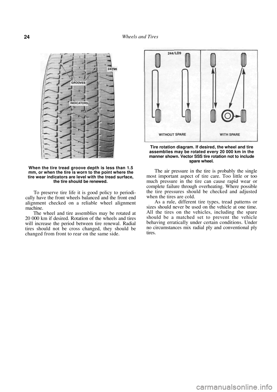
When the tire tread groove depth is less than 1.5
mm, or when the tire is worn to the point where the
tire wear indicators are level with the tread surface,
the tire should be renewed.
To preserve tire life it is good policy to periodi-
cally have the front wheels balanced and the front end
alignment checked on a reliable wheel alignment
machine.
The wheel and tire assemblies may be rotated at
20 000 km if desired. Rotation of the wheels and tires
will increase the period between tire renewal. Radial
tires should not be cross changed, they should be
changed from front to rear on the same side.
Tire rotation diagram. If desired, the wheel and tire
assemblies may be rotated every 20 000 km in the
manner shown. Vector SSS tire rotation not to include
spare wheel.
The air pressure in the tire is probably the single
most important aspect of tire care. Too little or too
much pressure in the tire can cause rapid wear or
complete failure through overheating. Where possible
the tire pressures should be checked and adjusted
when the tires are cold.
As a rule, different tire types, tread patterns or
sizes should never be used on the vehicle at one time.
All the tires on the vehicles, including the spare
should be a matched set to prevent the vehicle
behaving erratically under certain conditions. Under
no circumstances mix radial ply and conventional ply
tires.
Page 25 of 238
25
ENGINE TUNE-UP
CAUTION: To prevent severe electrical shock, extreme care must be taken when
working on or near the electronic ignition system as dangerous high tension voltages
are produced in both the primary and secondary circuits. See the text fo\
r
precautionary notes.
1. TUNE-UP SPECIFICATIONS
Firing orde r................................................... 1 -3-4-2
Spark plugs:
Type .............................................NGK BPR 6ES
Gap ........................................................... 1.1 mm
Tightening torque...................................... 20 Nm
Ignition timing with diagnostic link
connector jumped........................... 10 deg BTDC
Idle speed (ECU controlled):
Manual transaxle 1.8 liter ............ 850 ± 50 rpm
Manual transaxle 1.6 liter............800 ± 50 rpm
Automatic transaxle
(Park or Neutral).......................... 825 ± 50 rpm
Drive belt deflection:
Alternator ........................................... 14-16 mm
Power steering pump ......................... 14-16 mm
Air conditioner compressor .................. 9-11 mm
NOTE: When performing an engine tune-
up, a/ways compare the above Specifications
with the emission control information label
inside the engine compartment.
2. TUNE-UP OPERATIONS
Special Equipment Required:
To Test Compression — Compression gauge
TO SERVICE AIR CLEANER
The air cleaner is equipped with a paper element.
The element should be regu larly inspected but should
not be cleaned in service.
The element should be renewed every 40 000 km.
This distance is only a guide for normal operating
conditions and should be reduced accordingly if the
vehicle is operating under ex tremely dusty conditions.
NOTE: Paper air cleaner elements should
not be washed in petrol or any other type of
cleaning solvent. If the element has been
washed in solvent or has become oil soaked,
it should be discarded and a new element
installed.
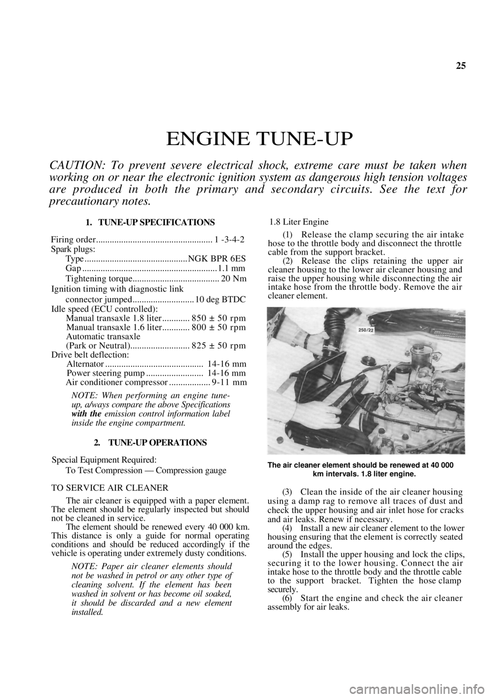
1.8 Liter Engine
(1) Release the clamp securing the air intake
hose to the throttle body and disconnect the throttle
cable from the support bracket. (2) Release the clips reta ining the upper air
cleaner housing to the lowe r air cleaner housing and
raise the upper housing while disconnecting the air
intake hose from the throttle body. Remove the air
cleaner element.
The air cleaner element should be renewed at 40 000
km intervals. 1.8 liter engine.
(3) Clean the inside of the air cleaner housing
using a damp rag to remove all traces of dust and
check the upper housing and air inlet hose for cracks
and air leaks. Renew if necessary. (4) Install a new air cleaner element to the lower
housing ensuring that the element is correctly seated
around the edges. (5) Install the upper housing and lock the clips,
securing it to the lower housing. Connect the air
intake hose to the throttle body and the throttle cable
to the support bracket. Tighten the hose clamp
securely. (6) Start the engine and check the air cleaner
assembly for air leaks.
Page 26 of 238
26 Engine Tune-up
1.6 Liter Engine
(1) Remove the nuts and washers securing the
upper air cleaner housing to the lower air cleaner
housing and release the retaining clips. (2) Remove the air cleaner element.
(3) Clean the inside of the air cleaner housing
using a damp rag to remo ve all traces of dust.
(4) Install a new air cleaner element ensuring that
the element is correctly seated around the edges.
(5) Install the upper housing and secure the
retaining clips. Tighten th e retaining nuts securely.
TO RENEW FUEL FILTER
filter should
The fuel
40 000 km.
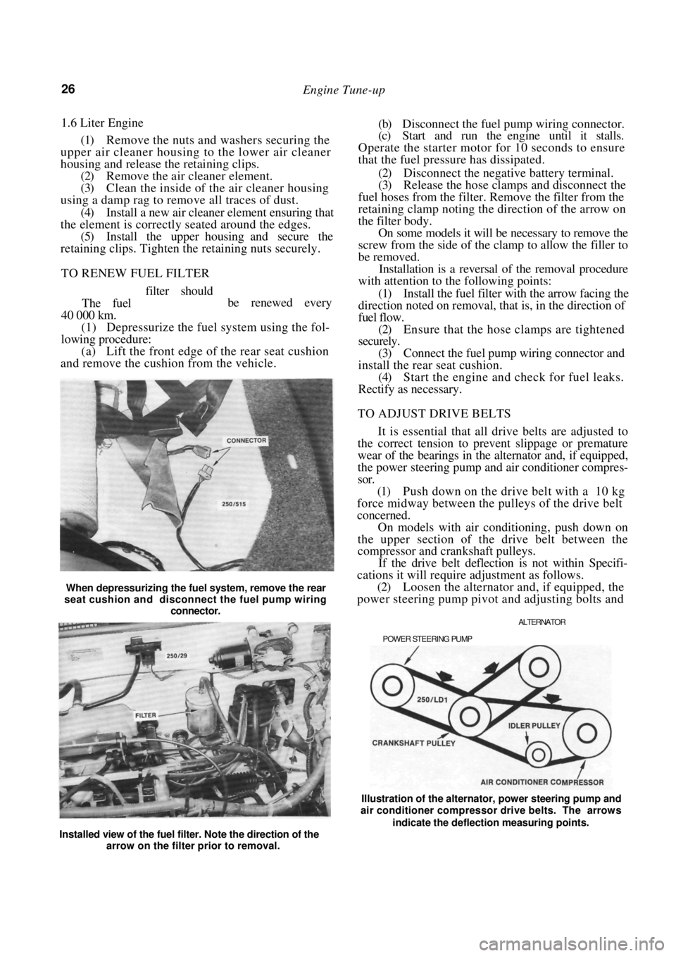
(1) Depressurize the fuel system using the fol-
lowing procedure:
(a) Lift the front edge of the rear seat cushion
and remove the cushion from the vehicle.
When depressurizing the fuel system, remove the rear
seat cushion and disconnect the fuel pump wiring
connector.
(b) Disconnect the fuel pump wiring connector.
(c) Start and run the engine until it stalls.
Operate the starter motor for 10 seconds to ensure
that the fuel pressure has dissipated.
(2) Disconnect the negative battery terminal.
(3) Release the hose clamps and disconnect the
fuel hoses from the filter. Remove the filter from the
retaining clamp noting the direction of the arrow on
the filter body. On some models it will be necessary to remove the
screw from the side of the clamp to allow the filler to
be removed.
Installation is a reversal of the removal procedure
with attention to the following points:
(1) Install the fuel filter with the arrow facing the
direction noted on removal, that is, in the direction of
fuel flow.
(2) Ensure that the hose clamps are tightened
securely.
(3) Connect the fuel pump wiring connector and
install the rear seat cushion. (4) Start the engine and check for fuel leaks.
Rectify as necessary.
TO ADJUST DRIVE BELTS
It is essential that all drive belts are adjusted to
the correct tension to prevent slippage or premature
wear of the bearings in the alternator and, if equipped,
the power steering pump and air conditioner compres-
sor.
(1) Push down on the drive belt with a 10 kg
force midway between the pulleys of the drive belt
concerned.
On models with air conditioning, push down on
the upper section of the drive belt between the
compressor and crankshaft pulleys.
If the drive belt deflection is not within Specifi-
cations it will require adjustment as follows.
(2) Loosen the alternator and, if equipped, the
power steering pump pivot and adjusting bolts and
ALTERNATOR
POWER STEERING PUMP
be renewed every
Installed view of the fuel filter. Note the direction of the arrow on the filter prior to removal. Illustration of the alternator, power steering pump and
air conditioner compressor drive belts. The arrows
indicate the deflection measuring points.
Page 27 of 238
Engine Tune-up 27
move the alternator or power steering pump as
required until the drive belt concerned has the
specified deflection.
On models with air conditioning, loosen the nut
in the centre of the idler pulley and turn the adjusting
bolt until the drive belt has the specified deflection.
(3) Tighten the alternator or power steering
pump bolts securely and check the belt tension.
On models with air conditioning, tighten the idler
pulley nut securely.
TO SERVICE SPARK PLUGS
The spark plugs should be renewed at intervals of
40 000 km.
Before removing the spark plugs ensure that the
area around each plug is cl ean to prevent foreign
matter entering the cylinder when the plugs are
removed.
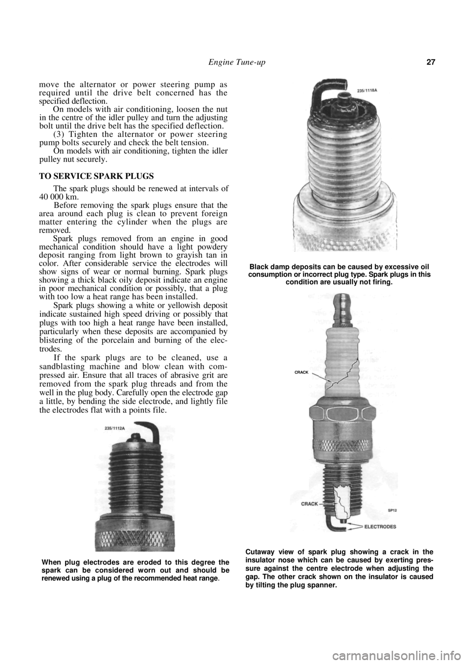
Spark plugs removed from an engine in good
mechanical condition should have a light powdery
deposit ranging from light brown to grayish tan in
color. After considerable service the electrodes will
show signs of wear or no rmal burning. Spark plugs
showing a thick black oily deposit indicate an engine
in poor mechanical condition or possibly, that a plug
with too low a heat range has been installed.
Spark plugs showing a white or yellowish deposit
indicate sustained high speed driving or possibly that
plugs with too high a heat range have been installed,
particularly when these deposits are accompanied by
blistering of the porcelain and burning of the elec-
trodes.
If the spark plugs are to be cleaned, use a
sandblasting machine and blow clean with com-
pressed air. Ensure that all traces of abrasive grit are
removed from the spark plug threads and from the
well in the plug body. Carefully open the electrode gap
a little, by bending the side electrode, and lightly file
the electrodes flat with a points file.
Black damp deposits can be caused by excessive oil
consumption or incorrect plug type. Spark plugs in this
condition are usually not firing.
Cutaway view of spark plug showing a crack in the
insulator nose which can be caused by exerting pres-
sure against the centre electrode when adjusting the
gap. The other crack shown on the insulator is caused
by tilting the plug spanner.
When plug electrodes are eroded to this degree the
spark can be considered worn out and should be
renewed using a plug of the recommended heat range
.
CRACK
Page 28 of 238
Engine Tune-up
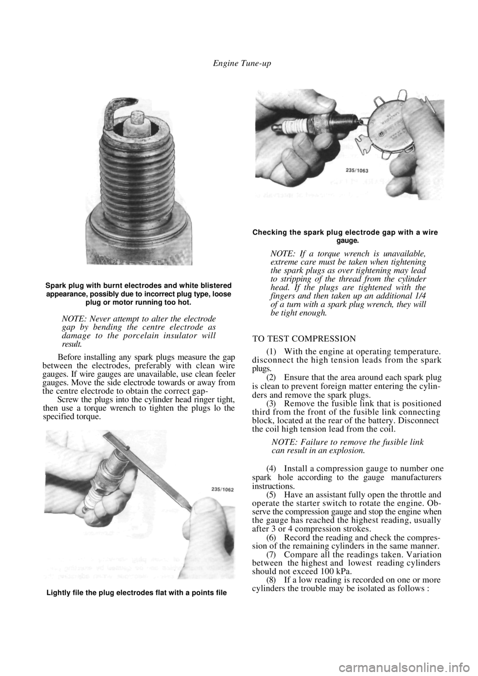
Spark plug with burnt electrodes and white blistered
appearance, possibly due to incorrect plug type, loose
plug or motor running too hot.
NOTE: Never attempt to alter the electrode
gap by bending the centre electrode as
damage to the porcelain insulator will
result.
Before installing any spark plugs measure the gap
between the electrodes, pref erably with clean wire
gauges. If wire gauges are una vailable, use clean feeler
gauges. Move the side electrode towards or away from
the centre electrode to obtain the correct gap-
Screw the plugs into the cylinder head ringer tight,
then use a torque wrench to tighten the plugs lo the
specified torque.
Checking the spark plug electrode gap with a wire
gauge.
NOTE: If a torque wrench is unavailable,
extreme care must be taken when tightening
the spark plugs as over tightening may lead
to stripping of the thread from the cylinder
head. If the plugs are tightened with the
fingers and then taken up an additional 1/4
of a turn with a spark plug wrench, they will
be tight enough.
TO TEST COMPRESSION
(1) With the engine at operating temperature.
disconnect the high tension leads from the spark
plugs.
(2) Ensure that the area around each spark plug
is clean to prevent foreign matter entering the cylin-
ders and remove the spark plugs. (3) Remove the fusible link that is positioned
third from the front of th e fusible link connecting
block, located at the rear of the battery. Disconnect
the coil high tension lead from the coil.
NOTE: Failure to remove the fusible link
can result in an explosion.
(4) Install a compression gauge to number one
spark hole according to the gauge manufacturers
instructions. (5) Have an assistant fully open the throttle and
operate the starter switch to rotate the engine. Ob-
serve the compression gauge and stop the engine when
the gauge has reached the highest reading, usually
after 3 or 4 compression strokes.
(6) Record the reading a nd check the compres-
sion of the remaining cylinders in the same manner.
(7) Compare all the readings taken. Variation
between the highest and lowest reading cylinders
should not exceed 100 kPa. (8) If a low reading is recorded on one or more
cylinders the trouble may be isolated as follows :
Lightly file the plug electrodes flat with a points file
Page 29 of 238
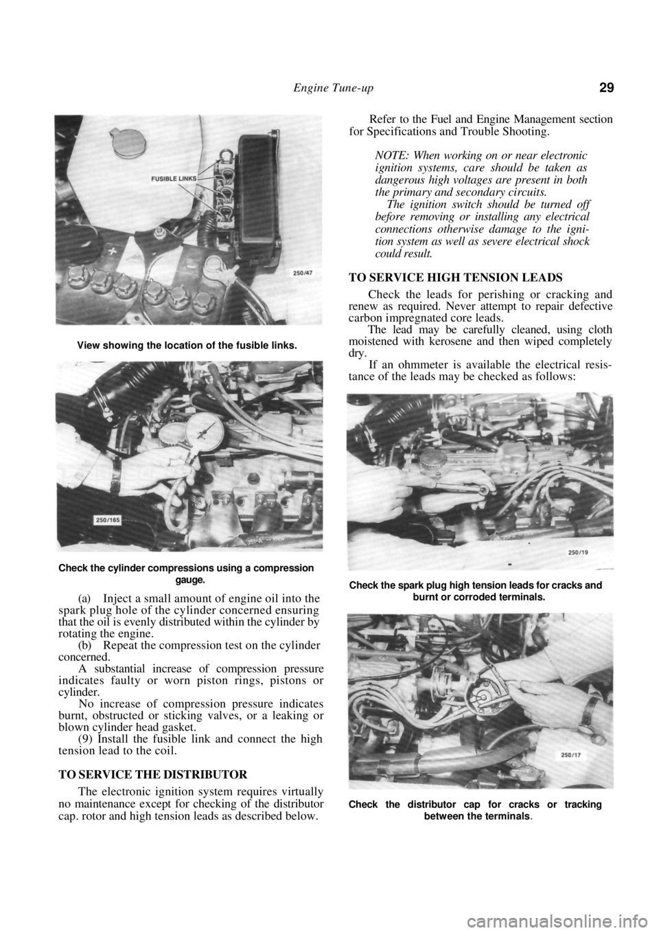
Engine Tune-up 29
Check the cylinder compressions using a compression gauge.
(a) Inject a small amount of engine oil into the
spark plug hole of the cylinder concerned ensuring
that the oil is evenly distributed within the cylinder by
rotating the engine.
(b) Repeat the compression test on the cylinder
concerned.
A substantial increase of compression pressure
indicates faulty or worn piston rings, pistons or
cylinder.
No increase of compression pressure indicates
burnt, obstructed or sticking valves, or a leaking or
blown cylinder head gasket.
(9) Install the fusible li nk and connect the high
tension lead to the coil.
TO SERVICE THE DISTRIBUTOR
The electronic ignition system requires virtually
no maintenance except for checking of the distributor
cap. rotor and high tension leads as described below.
Refer to the Fuel and Engine Management section
for Specifications and Trouble Shooting.
NOTE: When working on or near electronic
ignition systems, care should be taken as
dangerous high voltages are present in both
the primary and secondary circuits.
The ignition switch should be turned off
before removing or inst alling any electrical
connections otherwise damage to the igni-
tion system as well as severe electrical shock
could result.
TO SERVICE HIGH TENSION LEADS
Check the leads for perishing or cracking and
renew as required. Never a ttempt to repair defective
carbon impregnated core leads.
The lead may be carefully cleaned, using cloth
moistened with kerosene a nd then wiped completely
dry.
If an ohmmeter is available the electrical resis-
tance of the leads may be checked as follows:
View showing the location of the fusible links.
Check the spark plug high tension leads for cracks and
burnt or corroded terminals.
Check the distributor cap for cracks or tracking
between the terminals
.
Page 30 of 238
30 Engine Tune-up
(1) With the distributor cap and leads removed
as an assembly, test one lead at a time, connecting the
meter probes at the spark plug end of the lead and at
the corresponding terminal in side the cap. Resistance
should be less than 15 000 ohms.
(2) If the resistance is more than 15 000 ohms
remove the lead from the distributor cap and check
(he resistance in the lead only. The lead should be
renewed if the resistance is still more than 15 000
ohms. (3) High distributor cap resistance may be due
to corrosion deposits on the cap terminals. These
deposits should be removed with a small scraper or
emery cloth. Check the distributor cap for cracks or tracking
between the high tension terminals on both the inside
and outside of the cap. Renew the cap if cracks or
tracking are evident.
Check the carbon brush in the centre of the
distributor cap for evidence of arcing and renew as
necessary.
Check the condition of the rotor and renew if
arced excessively or cracked.
HOW TO CONNECT ELECTRICAL TEST
EQUIPMENT
NOTE: Some types of tachometers, timing
lights and ignition system analysers are not
compatible with this type of electronic igni-
tion system and may result in incorrect
readings. It is therefore recommended that
the manufacturer of the test equipment be
consulted before using the equipment.
Do not allow the tachometer lead connec-
tor to short to earth as damage to the test
equipment or ignition system may result.
Timing Light
(1) Connect the timing light to the engine fol-
lowing the instrument manufacturers instructions.
NOTE: Do not connect or disconnect the
timing light with the engine running as
voltage surges could damage the alternator.
Do not allow the high tension leads to open
circuit as damage to the ignition system
could result.
(2) Where necessary, connect the power leads of
the timing light to an external power source to prevent
possible transient voltages in the timing light damag-
ing the vehicle alternator.
Tachometer
(1) Ensure that the tachometer is compatible
with the vehicle ignition system. (2) Disconnect the resistor from the tachometer
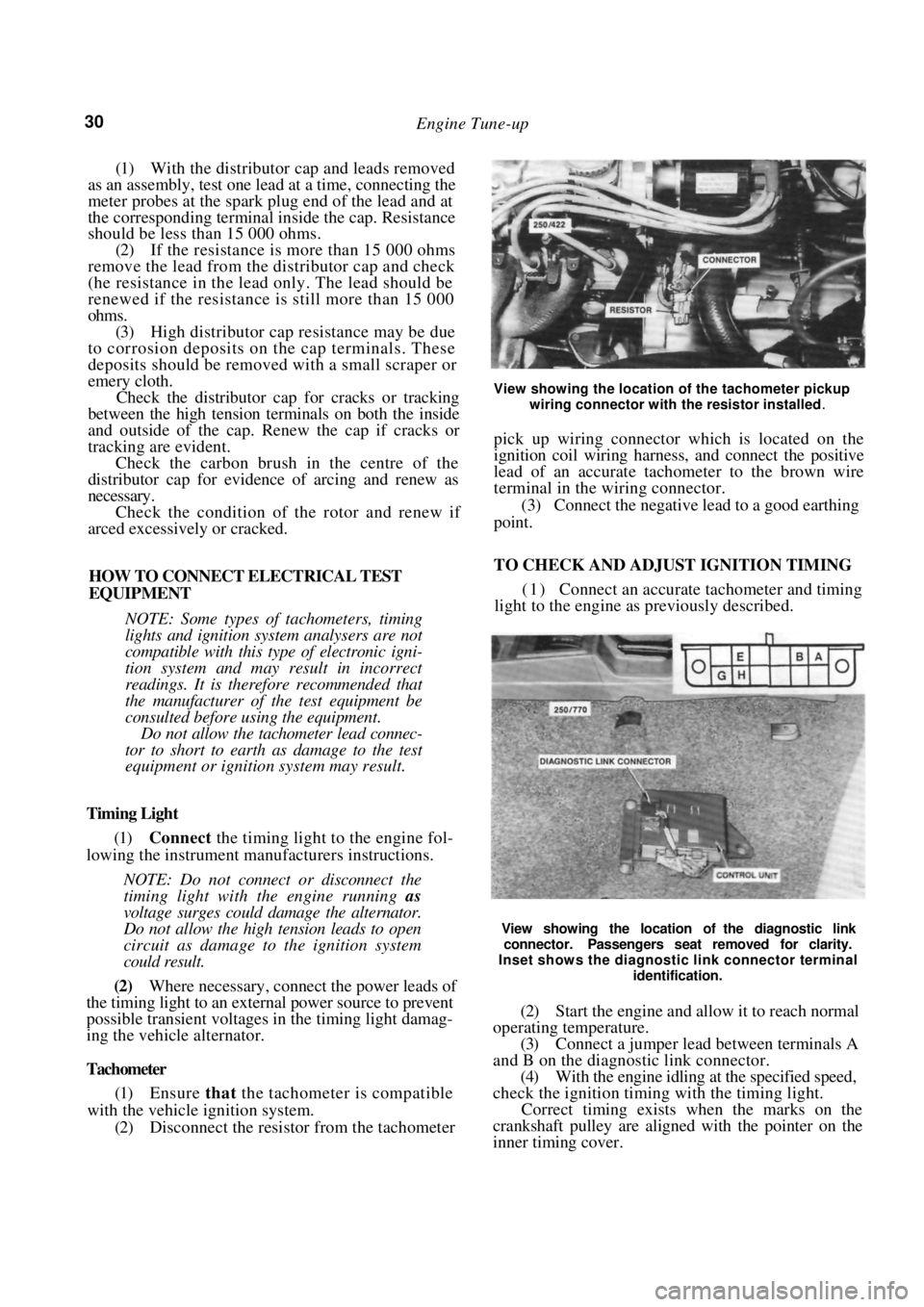
View showing the location of the tachometer pickup
wiring connector with the resistor installed
.
pick up wiring connector which is located on the
ignition coil wiring harness, and connect the positive
lead of an accurate tachometer to the brown wire
terminal in the wiring connector.
(3) Connect the negative lead to a good earthing
point.
TO CHECK AND ADJUST IGNITION TIMING
( 1 ) Connect an accurate tachometer and timing
light to the engine as previously described.
View showing the location of the diagnostic link
connector. Passengers seat removed for clarity.
Inset shows the diagnostic link connector terminal
identification.
(2) Start the engine and allow it to reach normal
operating temperature. (3) Connect a jumper lead between terminals A
and B on the diagnostic link connector. (4) With the engine idling at the specified speed,
check the ignition timing with the timing light.
Correct timing exists when the marks on the
crankshaft pulley are aligned with the pointer on the
inner timing cover.