NISSAN PULSAR 1987 Repair Manual
Manufacturer: NISSAN, Model Year: 1987, Model line: PULSAR, Model: NISSAN PULSAR 1987Pages: 238, PDF Size: 28.91 MB
Page 61 of 238
Engine 61
rear main bearing cap and engine block. Discard the
oil seal.
(3) Ensure that all main bearing and connecting
rod bearing caps are numbered to ensure correct
assembly. (4) Remove the connecting rod bolts and caps,
keeping them in order. Push each piston and connect-
ing rod slightly up into the bore without pushing the
piston beyond its upper limit. (5) Check the crankshaft end float by inserting a
feeler gauge between the shaft and the centre main
bearing, or by mounting a dial gauge with its plunger
against one end of the shaft. (6) Push the crankshaft into contact with the
front edge of the centre main bearing, then lever the
shaft forward to determine the end float.
(7) If the end float exceeds the Specifications,
renew the centre main bearing on assembly. (8) Check the main bearing clearance by the
Plastigage method as follows:
(a) Remove one bearing cap and with a piece of
rag wipe the journal and bearing clean.
(b) Position a piece of Plastigage, the approxi-
mate length of the bearing width and slightly off
centre, on the bearing surface of the crankshaft
journal. (c) Install the bearing ca p and tighten the cap
bolts to the specified torque.
NOTE: Do not rotate the crankshaft while
the Plastigage is in position.
(d) Remove the cap bolts and carefully detach
the cap and lower half bearing. (e) With the Plastigage scal e, measure the com-
pressed Plastigage strip to determine the clearance. (f) The widest point of the strip will indicate the
minimum clearance and th e narrowest point the
maximum clearance. (g) The remaining bearings can be checked in
turn using the same procedure.
(9) Lift the crankshaft from the crankcase using
care not to dislodge or damage the upper halves of the
main bearing shells if they are to be used again. (10) If new bearing shells are to be installed,
remove the upper halves of the bearings from the
crankcase.
TO CHECK AND INSPECT
After thoroughly cleaning the crankshaft in sol-
vent and drying it with co mpressed air, blow out all
the oilways and make the following checks:
(1) Check and measure the main bearing jour-
nals and crankpins for wear, taper and scoring. If wear
is excessive, the journals and/or crankpins should be
ground to accommodate the nearest underside bearing
shells.
One worn or damaged journal or crankpin will
necessitate the grinding of all the journals or crank-
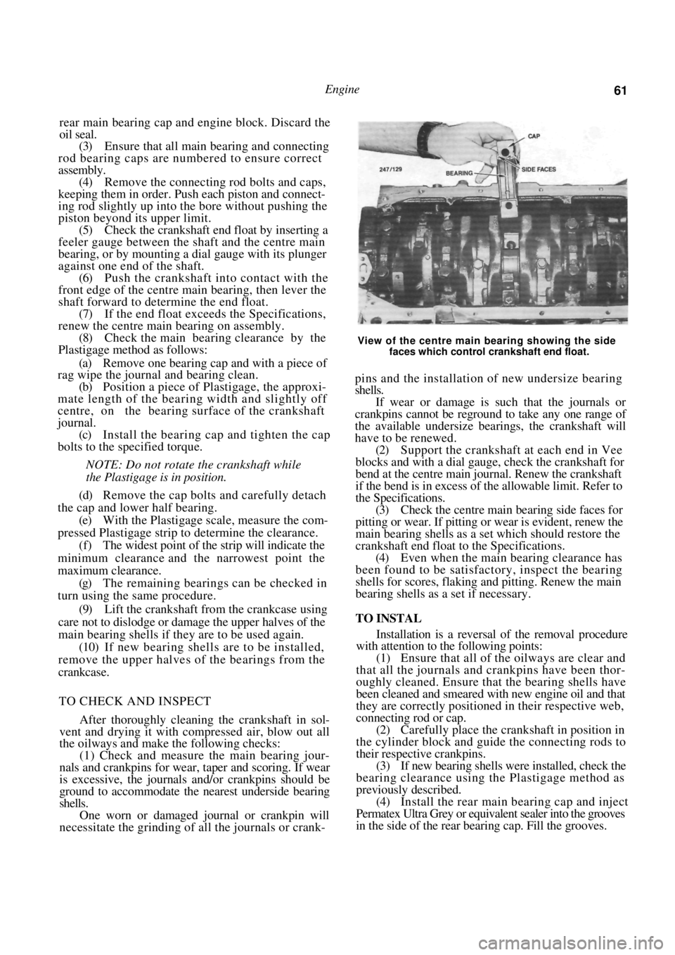
View of the centre main bearing showing the side
faces which control crankshaft end float.
pins and the installation of new undersize bearing
shells.
If wear or damage is such that the journals or
crankpins cannot be reground to take any one range of
the available undersize bearings, the crankshaft will
have to be renewed.
(2) Support the crankshaft at each end in Vee
blocks and with a dial gauge, check the crankshaft for
bend at the centre main jour nal. Renew the crankshaft
if the bend is in excess of the allowable limit. Refer to
the Specifications.
(3) Check the centre main bearing side faces for
pitting or wear. If pitting or wear is evident, renew the
main bearing shells as a set which should restore the
crankshaft end float to the Specifications. (4) Even when the main bearing clearance has
been found to be satisfact ory, inspect the bearing
shells for scores, flaking and pitting. Renew the main
bearing shells as a set if necessary.
TO INSTAL
Installation is a reversal of the removal procedure
with attention to the following points:
(1) Ensure that all of the oilways are clear and
that all the journals and crankpins have been thor-
oughly cleaned. Ensure that the bearing shells have
been cleaned and smeared with new engine oil and that
they are correctly positioned in their respective web,
connecting rod or cap. (2) Carefully place the crankshaft in position in
the cylinder block and guide the connecting rods to
their respective crankpins.
(3) If new bearing shells were installed, check the
bearing clearance using the Plastigage method as
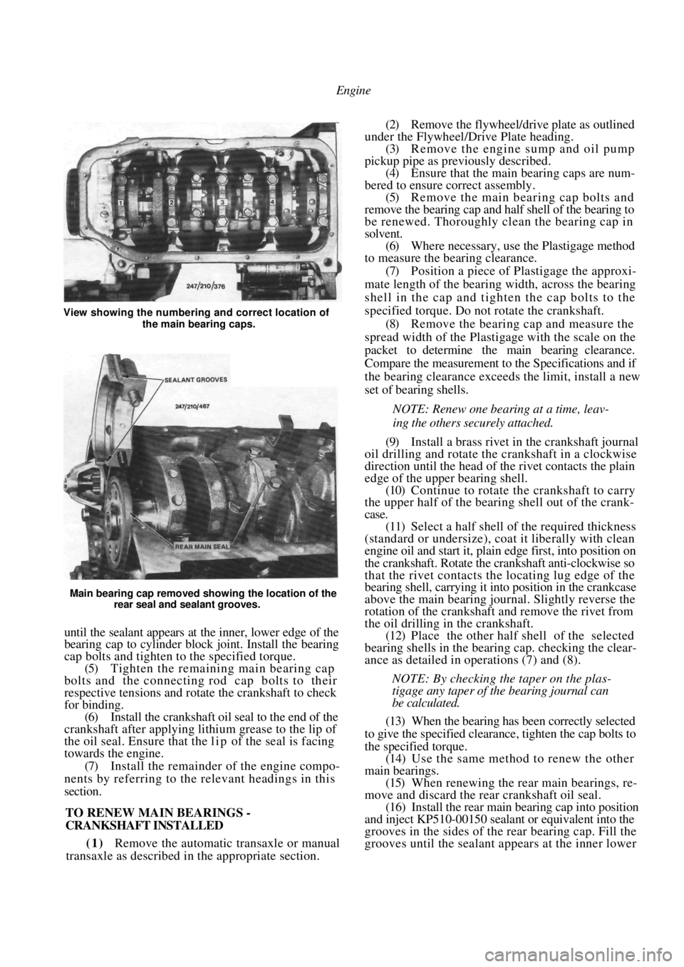
previously described. (4) Install the rear main bearing cap and inject
Permatex Ultra Grey or equivalent sealer into the grooves
in the side of the rear bearing cap. Fill the grooves.
Page 62 of 238
Engine
Main bearing cap removed showing the location of the rear seal and sealant grooves.
until the sealant appears at the inner, lower edge of the
bearing cap to cylinder block joint. Install the bearing
cap bolts and tighten to the specified torque.
(5) Tighten the remaining main bearing cap
bolts and the connecting rod cap bolts to their
respective tensions and rotate the crankshaft to check
for binding. (6) Install the crankshaft oil seal to the end of the
crankshaft after applying lithium grease to the lip of
the oil seal. Ensure that the l i p of the seal is facing
towards the engine.
(7) Install the remainder of the engine compo-
nents by referring to the relevant headings in this
section.
TO RENEW MAIN BEARINGS -
CRANKSHAFT INSTALLED
(1) Remove the automatic transaxle or manual
transaxle as described in the appropriate section.
(2) Remove the flywheel/drive plate as outlined
under the Flywheel/Drive Plate heading. (3) Remove the engine sump and oil pump
pickup pipe as previously described. (4) Ensure that the main bearing caps are num-
bered to ensure correct assembly. (5) Remove the main bearing cap bolts and
remove the bearing cap and half shell of the bearing to
be renewed. Thoroughly clean the bearing cap in
solvent. (6) Where necessary, use the Plastigage method
to measure the bearing clearance.
(7) Position a piece of Plastigage the approxi-
mate length of the bearing width, across the bearing
shell in the cap and tigh ten the cap bolts to the
specified torque. Do not rotate the crankshaft. (8) Remove the bearing cap and measure the
spread width of the Plastigage with the scale on the
packet to determine the main bearing clearance.
Compare the measurement to the Specifications and if
the bearing clearance exceeds the limit, install a new
set of bearing shells.
NOTE: Renew one bearing at a time, leav-
ing the others securely attached.
(9) Install a brass rivet in the crankshaft journal
oil drilling and rotate the crankshaft in a clockwise
direction until the head of the rivet contacts the plain
edge of the upper bearing shell. (10) Continue to rotate the crankshaft to carry
the upper half of the bearing shell out of the crank-
case.
(11) Select a half shell of the required thickness
(standard or undersize), coat it liberally with clean
engine oil and start it, plai n edge first, into position on
the crankshaft. Rotate the crankshaft anti-clockwise so
that the rivet contacts the locating lug edge of the
bearing shell, carrying it into position in the crankcase
above the main bearing journal. Slightly reverse the
rotation of the crankshaft and remove the rivet from
the oil drilling in the crankshaft. (12) Place the other half shell of the selected
bearing shells in the bear ing cap. checking the clear-
ance as detailed in operations (7) and (8).
NOTE: By checking the taper on the plas-
tigage any taper of the bearing journal can
be calculated.
(13) When the bearing has been correctly selected
to give the specified clearance, tighten the cap bolts to
the specified torque. (14) Use the same method to renew the other
main bearings. (15) When renewing the rear main bearings, re-
move and discard the rear crankshaft oil seal. (16) Install the rear main bearing cap into position
and inject KP510-00150 sealant or equivalent into the
grooves in the sides of the rear bearing cap. Fill the
grooves until the sealant a ppears at the inner lower
View showing the numbering and correct location of
the main bearing caps.
Page 63 of 238
Engine
edge of the bearing cap to cylinder block joint. Install
the bearing cap bolts and tighten to the specified
torque.
(17) Lubricate the l i p of the new oil seal with
lithium grease and carefully install the seal into
position over the crankshaft . Insert the seal as far as
possible using finger pressure and then fully install the
sea! using a tubular drift. Ensure that the seal is not
damaged during installation and that the seal is
mounted square to the block face.
(18) Install the remainder of the engine
compo-
nents by referring to the relevant headings in
this
section.
TO RENEW CRANKSHAFT OIL SEALS
Front
(1) Remove the camshaft drive belt as previ-
ously described.
(2) Disconnect the lower radiator hose and drain
the cooling system. (3) Select fifth gear on manual transaxle models
and firmly apply the handbrake. (4) On automatic transaxle models, remove the
torque converter inspection cover to allow access to
the ring gear. Have an assi stant hold the ring gear
using a suitable lever. (5) Remove the crankshaft timing gear retaining
bolt and discard. (6) Remove the crankshaft timing gear from the
crankshaft. It may be necessary to lever the gear from
the crankshaft using two screwdrivers. Remove the
key and spacer from the crankshaft. (7) Using a centre punch, tap a small hole in the
front face of the oil seal. (8) Insert a self tapping screw into the hole.
(9) Remove the seal from the oil pump by
gripping and pulling the end of the screw with a pair
of pliers. (10) Coat the l i p of a new seal with multi-purpose
grease. (11) Install the oil seal to the oil pump using a
tubular drift. Ensure that the lip of the oil seal faces
the inside of the housing.
(12) Install the remaining components in the re-
verse order of removal, usi ng a new crankshaft timing
gear retaining bolt and referring to the relevant
headings in this section as necessary.
Rear
(1) Remove the automatic transaxle or manual
transaxle as described in the appropriate section. (2) Remove the flywheel/drive plate as described
under the following heading. (3) Lever the oil seal from the rear of the
crankcase being careful not to damage the crankshaft.
(4) Coat the lip of a new seal with Lithium
grease.
(5) Install the oil seal over the crankshaft. Ensure
that the li p of the oil sea l faces towards the engine.
(6) Insert the seal as far as possible using finger
pressure, and then fully seat the seal using a tubular
drift. (7) Install the remaining components in the
re-
verse order of removal, referring to the relevant
headings in this section as necessary.
12. FLYWHEEL/DRIVE PLATE
Special Equipment Required:
To Renew Ring Gear — Suitable heat source
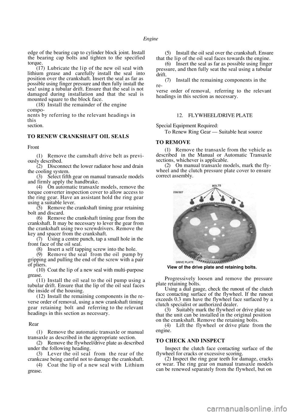
TO REMOVE
(1) Remove the transaxle from the vehicle as
described in the Manual or Automatic Transaxle
sections, whichever is applicable. (2) On manual transaxle models, mark the fly-
wheel and the clutch pressure plate cover to ensure
correct assembly.
View of the drive plate and retaining bolts.
Progressively loosen and remove the pressure
plate retaining bolts.
Using a dial gauge, check the runout of the clutch
face contacting surface of the flywheel. If the runout
exceeds 0.3 mm have the flywheel face surfaced by a
clutch specialist or authorized dealer.
(3) Suitably mark the flywheel or drive plate so
that the unit can be installed in the original position
on the crankshaft. Remove the retaining bolts. (4) Lift the flywheel or drive plate from the
engine.
TO CHECK AND INSPECT
Inspect the clutch face contacting surface of the
flywheel for cracks or excessive scoring.
(2) Inspect the ring gear teeth for damage, cracks
or wear. The ring gear on manual transaxle models
can be renewed separately from the flywheel, but on
Page 64 of 238
64 Engine
automatic transaxle models the complete drive plate
must be renewed.
(3) Inspect the drive plate bolt holes for elonga-
tion which is caused by loose retaining bolts.
(4) Inspect the drive plate for cracks.
(5) Repair or renew the flywheel if necessary.
TO INSTAL
Installation is a reversal of the removal procedure
with attention to the following points:
(1) The flywheel and drive plate retaining bolts
are special micro-encapsulated fasteners.
Install new micro-encapsulated bolts of the
correct
strength classification on assembly.
(2) Thoroughly clean the crankshaft threads with
a thread tap. Clean the threads with solvent and dry
before installing the flywh eel or drive plate retaining
bolts.
(3) Tighten the flywheel or drive plate retaining
bolts to the specified torque and on manual transaxle
models, align the clutch plate as described in the
Clutch section.
TO RENEW FLYWHEEL RING GEAR
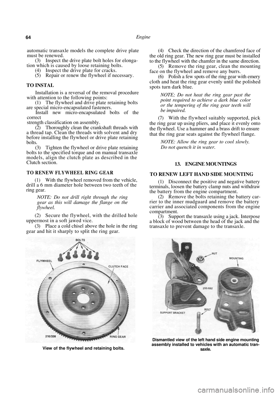
(1) With the flywheel removed from the vehicle,
drill a 6 mm diameter hole between two teeth of the
ring gear.
NOTE: Do not drill right through the ring
gear as this will damage the flange on the
flywheel.
(2) Secure the flywheel, with the drilled hole
uppermost in a soft jawed vice.
(3) Place a cold chisel above the hole in the ring
gear and hit it sharply to split the ring gear.
(4) Check the direction of the chamfered face of
the old ring gear. The new ring gear must be installed
to the flywheel with the chamfer in the same direction. (5) Remove the ring gear, clean the mounting
face on the flywheel and remove any burrs. (6) Polish a few spots of the ring gear with emery
cloth and heat the ring gear evenly until the polished
spots turn dark blue.
NOTE; Do not heat the ring gear past the
point required to achieve a dark blue color
or the tempering of the ring gear teeth will
be impaired.
(7) With the flywheel suitably supported, pick
the ring gear up using plie rs, and place it evenly onto
the flywheel. Use a hammer and a brass drift to ensure
that the ring gear seats ag ainst the flywheel flange.
NOTE: Allow the ring gear to cool slowly.
Do not quench it in water.
13. ENGINE MOUNTINGS
TO RENEW LEFT HAND SIDE MOUNTING
(1) Disconnect the positive and negative battery
terminals, loosen the battery clamp nuts and withdraw
the battery from the engine compartment.
(2) Remove the bolts retaining the battery car-
rier to the inner mudguard and remove the battery
carrier and associ ated components from the engine
compartment. (3) Support the transaxle using a jack. Interpose
a block of wood between the head of the jack and the
transaxle to prevent damage to the transaxle.
View of the flywheel and retaining bolts.
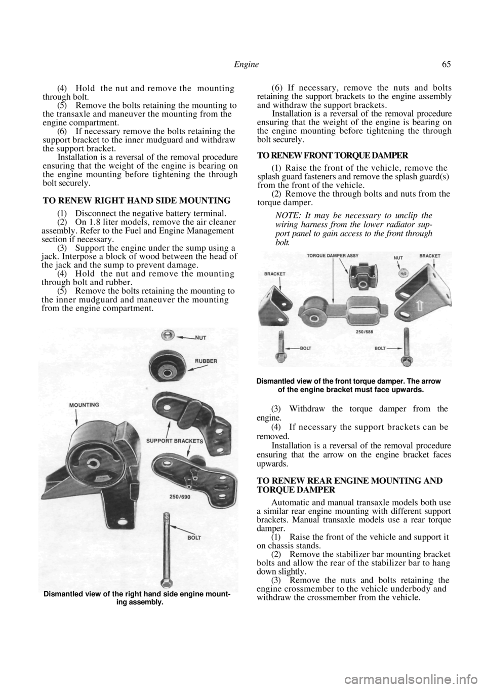
Dismantled view of the left hand side engine mounting
assembly installed to vehicles with an automatic tran-
saxle.
Page 65 of 238
Engine 65
(4) Hold the nut and remove the mounting
through bolt. (5) Remove the bolts retaining the mounting to
the transaxle and maneuver the mounting from the
engine compartment. (6) If necessary remove the bolts retaining the
support bracket to the inner mudguard and withdraw
the support bracket. Installation is a reversal of the removal procedure
ensuring that the weight of the engine is bearing on
the engine mounting before tightening the through
bolt securely.
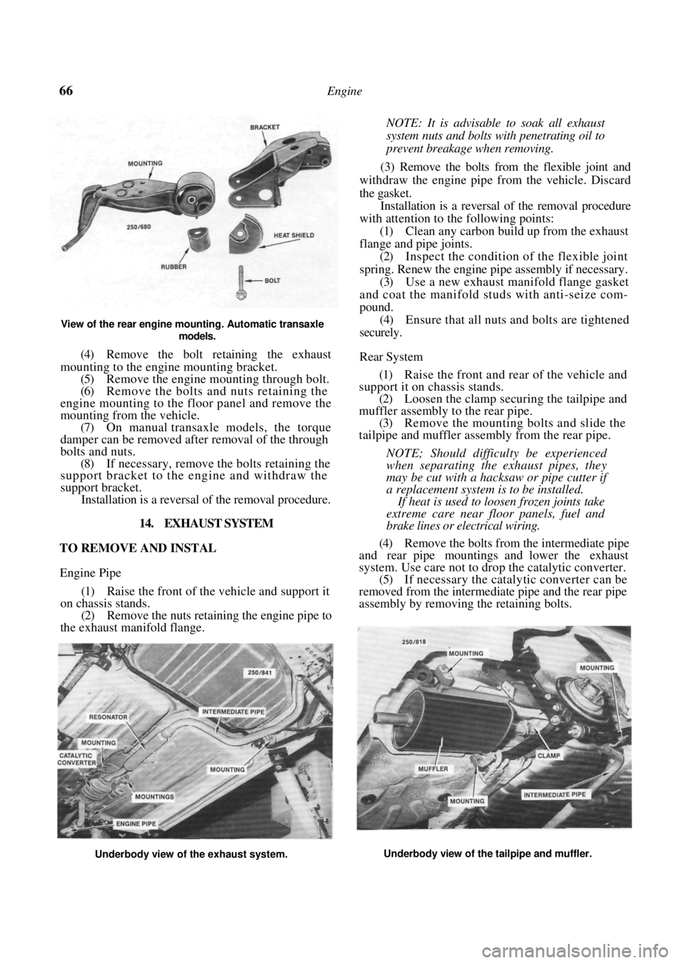
TO RENEW RIGHT HAND SIDE MOUNTING
(1) Disconnect the negative battery terminal.
(2) On 1.8 liter models, remove the air cleaner
assembly. Refer to the Fuel and Engine Management
section if necessary. (3) Support the engine under the sump using a
jack. Interpose a block of wood between the head of
the jack and the sump to prevent damage.
(4) Hold the nut and remove the mounting
through bolt and rubber. (5) Remove the bolts retain ing the mounting to
the inner mudguard and maneuver the mounting
from the engine compartment. (6) If necessary, remove the nuts and bolts
retaining the support brackets to the engine assembly
and withdraw the support brackets.
Installation is a reversal of the removal procedure
ensuring that the weight of the engine is bearing on
the engine mounting before tightening the through
bolt securely.
TO RENEW FRONT TORQUE DAMPER
(1) Raise the front of the vehicle, remove the
splash guard fasteners and remove the splash guard(s)
from the front of the vehicle.
(2) Remove the through bolts and nuts from the
torque damper.
NOTE: It may be necessary to unclip the
wiring harness from the lower radiator sup-
port panel to gain access to the front through
bolt.
Dismantled view of the front torque damper. The arrow of the engine bracket must face upwards.
(3) Withdraw the torque damper from the
engine.
(4) If necessary the support brackets can be
removed. Installation is a reversal of the removal procedure
ensuring that the arrow on the engine bracket faces
upwards.
TO RENEW REAR ENGINE MOUNTING AND
TORQUE DAMPER
Automatic and manual transaxle models both use
a similar rear engine moun ting with different support
brackets. Manual transaxle models use a rear torque
damper.
(1) Raise the front of the vehicle and support it
on chassis stands. (2) Remove the stabilizer bar mounting bracket
bolts and allow the rear of the stabilizer bar to hang
down slightly. (3) Remove the nuts and bolts retaining the
engine crossmember to the vehicle underbody and
withdraw the crossmember from the vehicle.
Dismantled view of the right hand side engine mount-
ing assembly.
Page 66 of 238
66 Engine
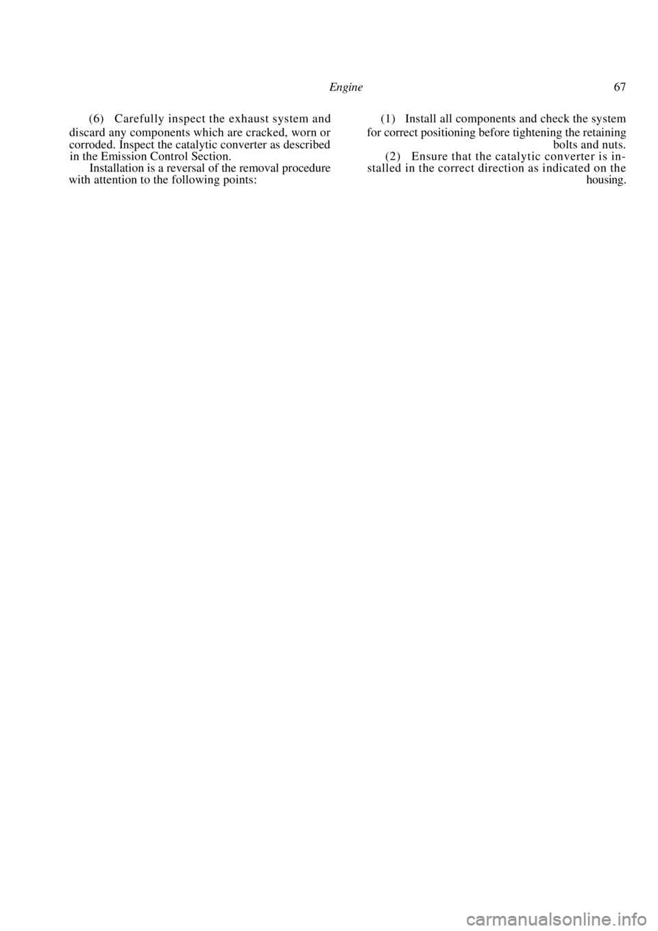
View of the rear engine mounting. Automatic transaxle models.
(4) Remove the bolt retaining the exhaust
mounting to the engine mounting bracket. (5) Remove the engine mounting through bolt.
(6) Remove the bolts and nuts retaining the
engine mounting to the floor panel and remove the
mounting from the vehicle.
(7) On manual transaxle models, the torque
damper can be removed after removal of the through
bolts and nuts. (8) If necessary, remove the bolts retaining the
support bracket to the engine and withdraw the
support bracket.
Installation is a reversal of the removal procedure.
14. EXHAUST SYSTEM
TO REMOVE AND INSTAL
Engine Pipe
(1) Raise the front of the vehicle and support it
on chassis stands. (2) Remove the nuts retaining the engine pipe to
the exhaust manifold flange.
NOTE: It is advisable to soak all exhaust
system nuts and bolts wi th penetrating oil to
prevent breakage when removing.
(3) Remove the bolts from the flexible joint and
withdraw the engine pipe from the vehicle. Discard
the gasket.
Installation is a reversal of the removal procedure
with attention to the following points:
(1) Clean any carbon build up from the exhaust
flange and pipe joints. (2) Inspect the condition of the flexible joint
spring. Renew the engine pipe assembly if necessary. (3) Use a new exhaust manifold flange gasket
and coat the manifold studs with anti-seize com-
pound. (4) Ensure that all nuts and bolts are tightened
securely.
Rear System
(1) Raise the front and rear of the vehicle and
support it on chassis stands. (2) Loosen the clamp securing the tailpipe and
muffler assembly to the rear pipe. (3) Remove the mounting bolts and slide the
tailpipe and muffler assembly from the rear pipe.
NOTE; Should difficulty be experienced
when separating the exhaust pipes, they
may be cut with a hacksaw or pipe cutter if
a replacement system is to be installed.
If heat is used to loosen frozen joints take
extreme care near floor panels, fuel and
brake lines or electrical wiring.
(4) Remove the bolts from the intermediate pipe
and rear pipe mountings and lower the exhaust
system. Use care not to drop the catalytic converter.
(5) If necessary the cataly tic converter can be
removed from the intermediate pipe and the rear pipe
assembly by removing the retaining bolts.
Underbody view of the exhaust system. Underbody view of the tailpipe and muffler.
Page 67 of 238
Engine 67
(6) Carefully inspect the exhaust system and (1) Install all components and check the system
discard any components which are cracked, worn or for correct pos itioning before tightening the retaining
corroded. Inspect the catalytic converter as described bolts and nuts.
in the Emission Control Section. (2) Ensure that the catalytic converter is in-
Installation is a reversal of the removal procedure stalled in the correct direction as indicated on the
with attention to the following points: housing.
Page 68 of 238
68
COOLING AND HEATING SYSTEMS
SPECIFICATIONS
Coolant capacity ........................................ 6.0 liters
Thermostat:
Opening temperature........................... 91 deg
C
Fully open temperature .................... 103 deg
C
Cooling fan:
Fan cut in temperat ure ....................... 100 deg C
Fan cut out temperature ...................... 95 deg C
Radiator cap opening
pressure ................................................... 78 -98 kPa
TORQUE WRENCH SETTINGS
Water pump retaining bolts .............................25 Nm
Thermostat housing bolts .................................15 Nm
Sender unit .......................................................10 Nm
1. COOLING SYSTEM TROUBLE SHOOTING
COOLANT LEAKAGE - EXTERNAL
(1) Loose hose clips or faulty hoses: Tighten the
hose clips or renew the faulty water hoses.
(2) Leaking radiator core or tanks: Repair or
renew the radiator. (3) Leaking heater core or hoses: Repair or renew the heater core. Check the hose clips and hoses
and renew if necessary.
(4)
Leaks at the thermostat cover and/or water
pump O rings. Renew the O rings. (5) Worn or damaged water pump seal assembly:
Renew the water pump. (6) Worn or damaged water pump bearing as-
sembly: Renew the water pump.
(7) Loose or rusted welch plugs; Renew the
welch plugs. (8) Faulty cylinder head gasket or loose cylinder
head bolts: Renew the cylinder head gasket and
correctly tighten the cylinder head bolts. (9) External crack in the cy linder head or cylin-
der block: Repair or renew the faulty components.
NOTE: Check the system for external leak-
age by running the engine to operating
temperature over a dry floor and checking
for the leak source.
Check the vehicle interior below the
heater core for moisture. If a rusted welch
plug is found, it is a good practice to renew
all the welch plugs.
COOLANT LEAKAGE - INTERNAL
( 1 ) Cylinder head gasket leak due to warped
cylinder head or cylinder block gasket faces: Reface
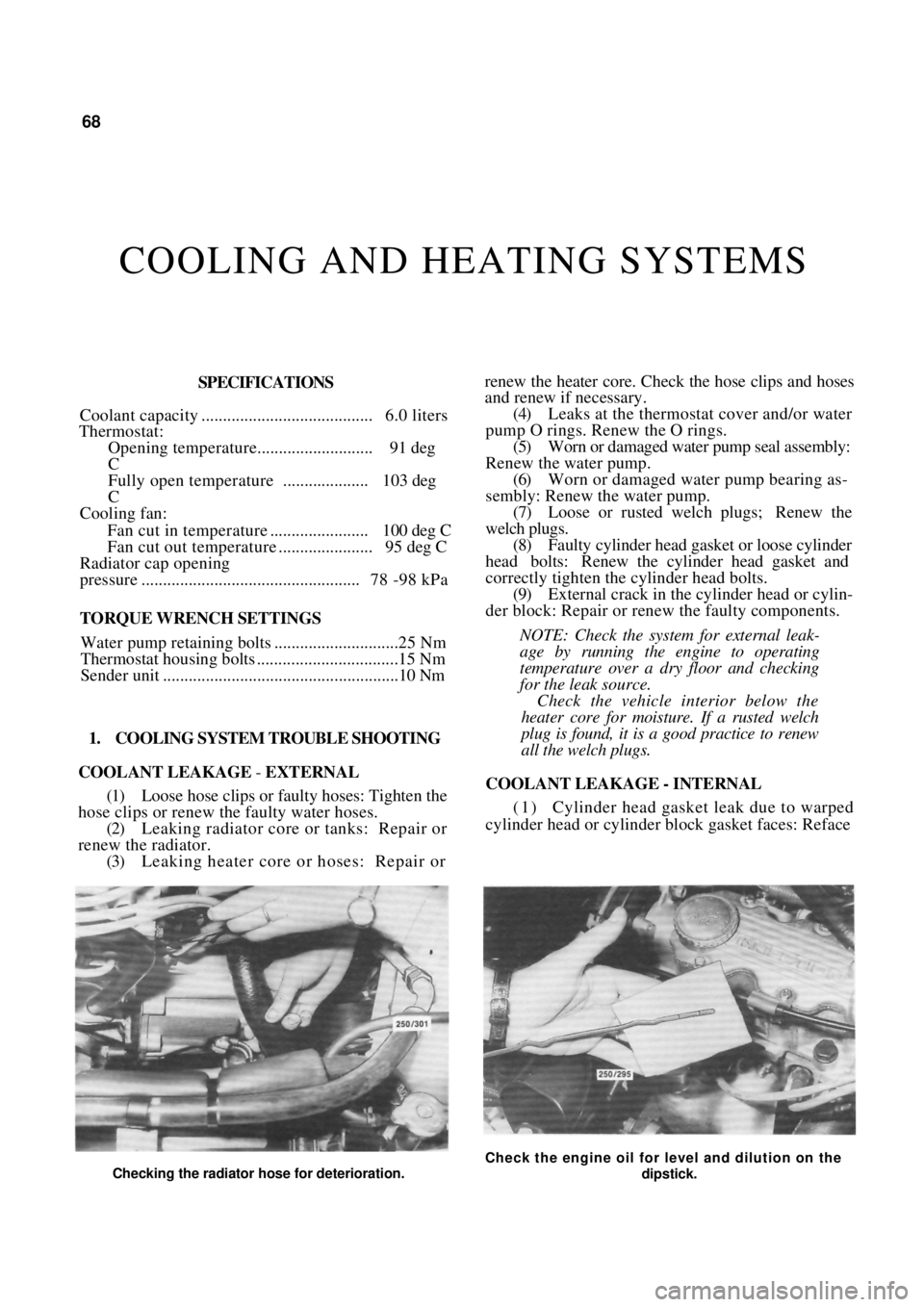
Checking the radiator hose for deterioration.
Check the engine oil for level and dilution on the
dipstick.
Page 69 of 238
Cooling and Heating Systems 69
the cylinder head or cylinder block and renew the
cylinder head gasket.
(2) Crack in the cylinder head or cylinder block:
Repair or renew as necessary.
NOTE; Check the engine for internal leak-
age by withdrawing the dipstick and inspect-
ing for emulsified oil. Run the engine and
check for excessive steam at the exhaust
pipe which would indi cate coolant leakage
into the combustion chamber.
COOLANT LOSS BY OVERFLOW
(1) Overfull system: Drain the excess coolant
from the system.
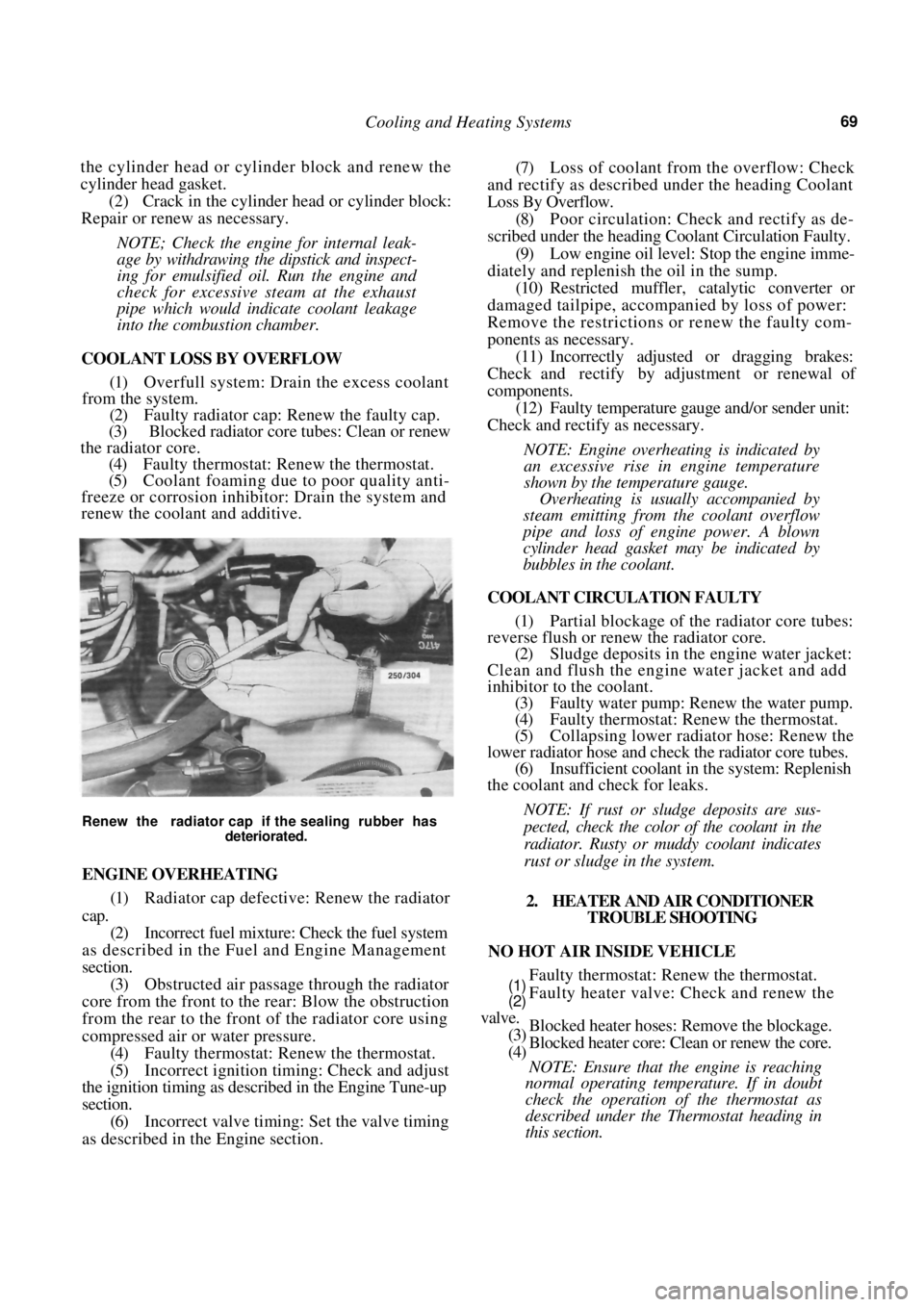
(2) Faulty radiator cap: Renew the faulty cap.
(3) Blocked radiator core tubes: Clean or renew
the radiator core.
(4) Faulty thermostat: Renew the thermostat.
(5) Coolant foaming due to poor quality anti-
freeze or corrosion inhibitor: Drain the system and
renew the coolant and additive.
Renew the radiator cap if the sealing rubber has
deteriorated.
ENGINE OVERHEATING
(1) Radiator cap defective: Renew the radiator
cap.
(2) Incorrect fuel mixture: Check the fuel system
as described in the Fuel and Engine Management
section. (3) Obstructed air passage through the radiator
core from the front to the rear: Blow the obstruction
from the rear to the front of the radiator core using
compressed air or water pressure. (4) Faulty thermostat: Renew the thermostat.
(5) Incorrect ignition timing: Check and adjust
the ignition timing as described in the Engine Tune-up
section. (6) Incorrect valve timing: Set the valve timing
as described in th e Engine section.
(7) Loss of coolant from the overflow: Check
and rectify as described under the heading Coolant
Loss By Overflow.
(8) Poor circulation: Check and rectify as de-
scribed under the heading Coolant Circulation Faulty.
(9) Low engine oil level: Stop the engine imme-
diately and replenish the oil in the sump. (10) Restricted muffler, catalytic converter or
damaged tailpipe, accompanied by loss of power:
Remove the restrictions or renew the faulty com-
ponents as necessary.
(11) Incorrectly adjusted or dragging brakes:
Check and rectify by adjustment or renewal of
components. (12) Faulty temperature gauge and/or sender unit:
Check and rectify as necessary.
NOTE: Engine overheating is indicated by
an excessive rise in engine temperature
shown by the temperature gauge.
Overheating is usually accompanied by
steam emitting from the coolant overflow
pipe and loss of engine power. A blown
cylinder head gasket may be indicated by
bubbles in the coolant.
COOLANT CIRCULATION FAULTY
(1) Partial blockage of the radiator core tubes:
reverse flush or renew the radiator core.
(2) Sludge deposits in the engine water jacket:
Clean and flush the engine water jacket and add
inhibitor to the coolant. (3) Faulty water pump: Renew the water pump.
(4) Faulty thermostat: Renew the thermostat.
(5) Collapsing lower radiator hose: Renew the
lower radiator hose and check the radiator core tubes. (6) Insufficient coolant in the system: Replenish
the coolant and check for leaks.
NOTE: If rust or sludge deposits are sus-
pected, check the color of the coolant in the
radiator. Rusty or muddy coolant indicates
rust or sludge in the system.
2. HEATER AND AIR CONDITIONER TROUBLE SHOOTING
NO HOT AIR INSIDE VEHICLE
Faulty thermostat: Renew the thermostat.
Faulty heater valve: Check and renew the
Blocked heater hoses: Remove the blockage.
Blocked heater core: Clean or renew the core.
NOTE: Ensure that the engine is reaching
normal operating temperature. If in doubt
check the operation of the thermostat as
described under the Thermostat heading in
this section.
(1)
(2)
valve.
(3)
(4)
Page 70 of 238
70 Cooling and Heating Systems
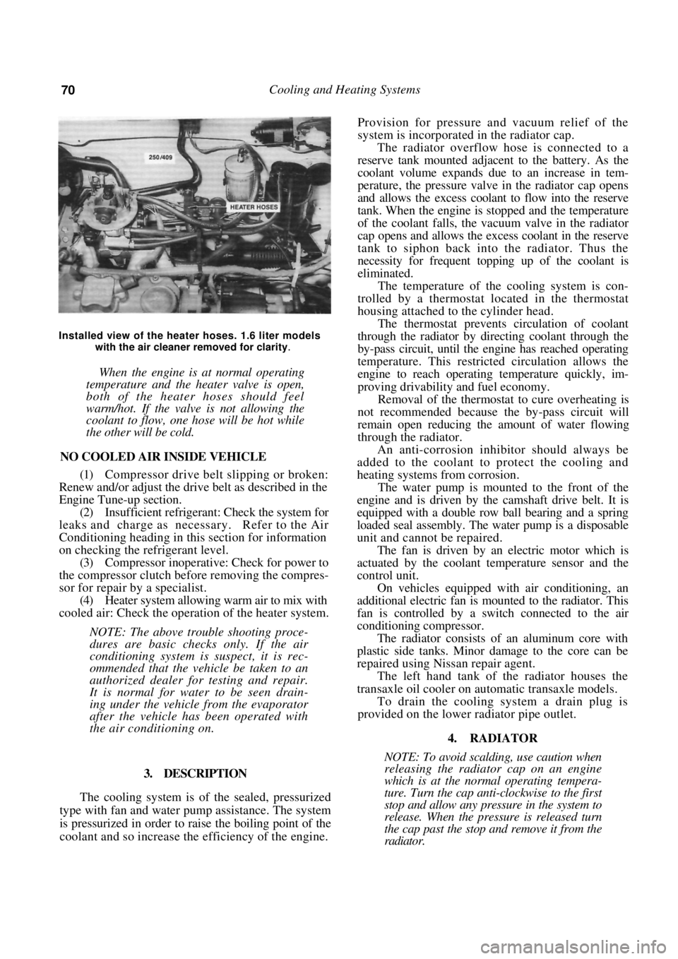
Installed view of the heater hoses. 1.6 liter models with the air cleaner removed for clarity
.
When the engine is at normal operating
temperature and the heater valve is open,
both of the heater hoses should feel
warm/hot. If the valve is not allowing the
coolant to flow, one hose will be hot while
the other will be cold.
NO COOLED AIR INSIDE VEHICLE
(1) Compressor drive belt slipping or broken:
Renew and/or adjust the drive belt as described in the
Engine Tune-up section.
(2) Insufficient refrigerant: Check the system for
leaks and charge as necessary. Refer to the Air
Conditioning heading in th is section for information
on checking the refrigerant level. (3) Compressor inoperative: Check for power to
the compressor clutch before removing the compres-
sor for repair by a specialist. (4) Heater system allowing warm air to mix with
cooled air: Check the operation of the heater system.
NOTE: The above trouble shooting proce-
dures are basic checks only. If the air
conditioning system is suspect, it is rec-
ommended that the vehicle be taken to an
authorized dealer for testing and repair.
It is normal for water to be seen drain-
ing under the vehicle from the evaporator
after the vehicle has been operated with
the air conditioning on.
3. DESCRIPTION
The cooling system is of the sealed, pressurized
type with fan and water pump assistance. The system
is pressurized in order to raise the boiling point of the
coolant and so increase the efficiency of the engine.
Provision for pressure a nd vacuum relief of the
system is incorporated in the radiator cap.
The radiator overflow hose is connected to a
reserve tank mounted adjacent to the battery. As the
coolant volume expands due to an increase in tem-
perature, the pressure valve in the radiator cap opens
and allows the excess coolant to flow into the reserve
tank. When the engine is stopped and the temperature
of the coolant falls, the vacuum valve in the radiator
cap opens and allows the excess coolant in the reserve
tank to siphon back into the radiator. Thus the
necessity for frequent topping up of the coolant is
eliminated.
The temperature of the cooling system is con-
trolled by a thermostat located in the thermostat
housing attached to the cylinder head.
The thermostat prevents circulation of coolant
through the radiator by directing coolant through the
by-pass circuit, until the engine has reached operating
temperature. This restricted circulation allows the
engine to reach operating temperature quickly, im-
proving drivability and fuel economy.
Removal of the thermostat to cure overheating is
not recommended because th e by-pass circuit will
remain open reducing the amount of water flowing
through the radiator.
An anti-corrosion inhibitor should always be
added to the coolant to protect the cooling and
heating systems from corrosion.
The water pump is mounted to the front of the
engine and is driven by the camshaft drive belt. It is
equipped with a double row ball bearing and a spring
loaded seal assembly. The water pump is a disposable
unit and cannot be repaired.
The fan is driven by an electric motor which is
actuated by the coolant temperature sensor and the
control unit.
On vehicles equipped with air conditioning, an
additional electric fan is m ounted to the radiator. This
fan is controlled by a sw itch connected to the air
conditioning compressor.
The radiator consists of an aluminum core with
plastic side tanks. Minor damage to the core can be
repaired using Nissan repair agent.
The left hand tank of the radiator houses the
transaxle oil cooler on automatic transaxle models.
To drain the cooling system a drain plug is
provided on the lower radiator pipe outlet.
4. RADIATOR
NOTE: To avoid scalding, use caution when
releasing the radiator cap on an engine
which is at the normal operating tempera-
ture. Turn the cap anti-clockwise to the first
stop and allow any pressure in the system to
release. When the pressure is released turn
the cap past the stop and remove it from the
radiator.