NISSAN TEANA 2008 Service Manual
Manufacturer: NISSAN, Model Year: 2008, Model line: TEANA, Model: NISSAN TEANA 2008Pages: 5121, PDF Size: 69.03 MB
Page 3171 of 5121
![NISSAN TEANA 2008 Service Manual LAN-104
< COMPONENT DIAGNOSIS >[CAN SYSTEM (TYPE 9)]
CAN COMMUNICATION CIRCUIT
CAN COMMUNICATION CIRCUIT
Diagnosis ProcedureINFOID:0000000003841820
1.CONNECTOR INSPECTION
1. Turn the ignition switch O NISSAN TEANA 2008 Service Manual LAN-104
< COMPONENT DIAGNOSIS >[CAN SYSTEM (TYPE 9)]
CAN COMMUNICATION CIRCUIT
CAN COMMUNICATION CIRCUIT
Diagnosis ProcedureINFOID:0000000003841820
1.CONNECTOR INSPECTION
1. Turn the ignition switch O](/img/5/57391/w960_57391-3170.png)
LAN-104
< COMPONENT DIAGNOSIS >[CAN SYSTEM (TYPE 9)]
CAN COMMUNICATION CIRCUIT
CAN COMMUNICATION CIRCUIT
Diagnosis ProcedureINFOID:0000000003841820
1.CONNECTOR INSPECTION
1. Turn the ignition switch OFF.
2. Disconnect the battery cable from the negative terminal.
3. Disconnect all the unit connectors on CAN communication system.
4. Check terminals and connectors for damage, bend and loose connection.
Is the inspection result normal?
YES >> GO TO 2.
NO >> Repair the terminal and connector.
2.CHECK HARNESS CONTINUITY (SHORT CIRCUIT)
Check the continuity between the data link connector terminals.
Is the inspection result normal?
YES >> GO TO 3.
NO >> Check the harness and repair the root cause.
3.CHECK HARNESS CONTINUITY (SHORT CIRCUIT)
Check the continuity between the data link connector and the ground.
Is the inspection result normal?
YES >> GO TO 4.
NO >> Check the harness and repair the root cause.
4.CHECK ECM AND IPDM E/R TERMINATION CIRCUIT
1. Remove the ECM and the IPDM E/R.
2. Check the resistance between the ECM terminals.
3. Check the resistance between the IPDM E/R terminals.
Is the measurement value within the specification?
YES >> GO TO 5.
NO >> Replace the ECM and/or the IPDM E/R.
5.CHECK SYMPTOM
Connect all the connectors. Check if the symptoms described in the “Symptom (Results from interview with
customer)” are reproduced.
Data link connector
Continuity
Connector No. Terminal No.
M4 6 14 Not existed
Data link connector
GroundContinuity
Connector No. Terminal No.
M46 Not existed
14 Not existed
ECM
Resistance (Ω)
Te r m i n a l N o .
98 97 Approx. 108 – 132
IPDM E/R
Resistance (Ω)
Te r m i n a l N o .
40 39 Approx. 108 – 132
LKIA0037E
Page 3172 of 5121
![NISSAN TEANA 2008 Service Manual LAN
CAN COMMUNICATION CIRCUIT
LAN-105
< COMPONENT DIAGNOSIS >[CAN SYSTEM (TYPE 9)]
C
D
E
F
G
H
I
J
K
L B A
O
P N
Inspection result
Reproduced>>GO TO 6.
Non-reproduced>>Start the diagnosis again. Follo NISSAN TEANA 2008 Service Manual LAN
CAN COMMUNICATION CIRCUIT
LAN-105
< COMPONENT DIAGNOSIS >[CAN SYSTEM (TYPE 9)]
C
D
E
F
G
H
I
J
K
L B A
O
P N
Inspection result
Reproduced>>GO TO 6.
Non-reproduced>>Start the diagnosis again. Follo](/img/5/57391/w960_57391-3171.png)
LAN
CAN COMMUNICATION CIRCUIT
LAN-105
< COMPONENT DIAGNOSIS >[CAN SYSTEM (TYPE 9)]
C
D
E
F
G
H
I
J
K
L B A
O
P N
Inspection result
Reproduced>>GO TO 6.
Non-reproduced>>Start the diagnosis again. Follow the trouble diagnosis procedure when past error is
detected.
6.CHECK UNIT REPRODUCTION
Perform the reproduction test as per the following procedure for each unit.
1. Turn the ignition switch OFF.
2. Disconnect the battery cable from the negative terminal.
3. Disconnect one of the unit connectors of CAN communication system.
NOTE:
ECM and IPDM E/R have a termination circuit. Check other units first.
4. Connect the battery cable to the negative terminal. Check if the symptoms described in the “Symptom
(Results from interview with customer)” are reproduced.
NOTE:
Although unit-related error symptoms occur, do not confuse them with other symptoms.
Inspection result
Reproduced>>Connect the connector. Check other units as per the above procedure.
Non-reproduced>>Replace the unit whose connector was disconnected.
Page 3173 of 5121

LU-1
ENGINE
C
DE
F
G H
I
J
K L
M
SECTION LU
A
LU
N
O P
CONTENTS
ENGINE LUBRICATION SYSTEM
FUNCTION DIAGNOSIS .. .............................2
DESCRIPTION ............................................... .....2
Engine Lubrication System ................................ ......2
Engine Lubrication System Schematic ......................3
PRECAUTION ...............................................4
PRECAUTIONS .............................................. .....4
Precaution for Liquid Gasket ............................... ......4
PREPARATION ............................................5
PREPARATION .............................................. .....5
Special Service Tool ........................................... ......5
Commercial Service Tool ..........................................5
ON-VEHICLE MAINTENANCE .....................7
ENGINE OIL ................................................... .....7
Inspection ............................................................ ......7
Draining .....................................................................8
Refilling .....................................................................9
OIL FILTER ........................................................10
Removal and Installation ..................................... ....10
Inspection ................................................................10
ON-VEHICLE REPAIR .................................11
OIL COOLER ....................................................11
Exploded View ..................................................... ....11
Removal and Installation .........................................11
Inspection ................................................................12
DISASSEMBLY AND ASSEMBLY ..............13
OIL PUMP .........................................................13
Exploded View ..................................................... ....13
Removal and Installation .........................................13
Disassembly and Assembly .....................................13
Inspection ................................................................14
SERVICE DATA AND SPECIFICATIONS
(SDS) ............... .............................................
16
SERVICE DATA AND SPECIFICATIONS
(SDS) .................................................................
16
Periodical Maintenance Specification ................ ....16
Engine Oil Pressure ...............................................16
Oil Pump .................................................................16
Regulator Valve ......................................................16
Page 3174 of 5121
LU-2
< FUNCTION DIAGNOSIS >
DESCRIPTION
FUNCTION DIAGNOSIS
DESCRIPTION
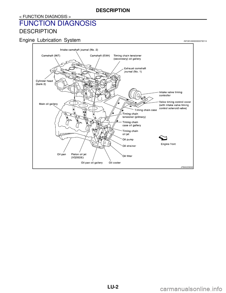
Engine Lubrication SystemINFOID:0000000003793114
JPBIA2239GB
Page 3175 of 5121
DESCRIPTION
LU-3
< FUNCTION DIAGNOSIS >
C
D
E
F
G
H
I
J
K
L
MA
LU
N
P O
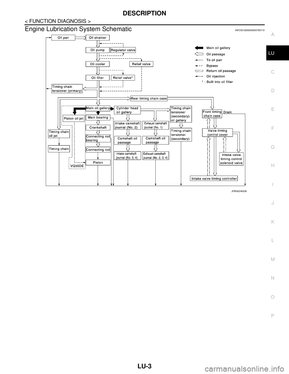
Engine Lubrication System SchematicINFOID:0000000003793115
JPBIA2240GB
Page 3176 of 5121

LU-4
< PRECAUTION >
PRECAUTIONS
PRECAUTION
PRECAUTIONS
Precaution for Liquid GasketINFOID:0000000003793117
LIQUID GASKET APPLICATION PROCEDURE
1. Remove old liquid gasket adhering to the liquid gasket application surface and the mating surface.
• Remove liquid gasket completely from the liquid gasket application surface, mounting bolts, and bolt
holes.
2. Wipe the liquid gasket application surface and the mating surface with white gasoline (lighting and heating
use) to remove adhering moisture, grease and foreign materials.
3. Apply liquid gasket to the liquid gasket application surface.
Use Genuine Liquid Gasket or equivalent.
Within 5 minutes of liquid gasket application, install the mating component.
If liquid gasket protrudes, wipe it off immediately.
Never retighten mounting bolts or nuts after the installation.
After 30 minutes or more have passed from the installation, fill engine oil and engine coolant.
Page 3177 of 5121
PREPARATION
LU-5
< PREPARATION >
C
D
E
F
G
H
I
J
K
L
MA
LU
N
P O
PREPARATION
PREPARATION
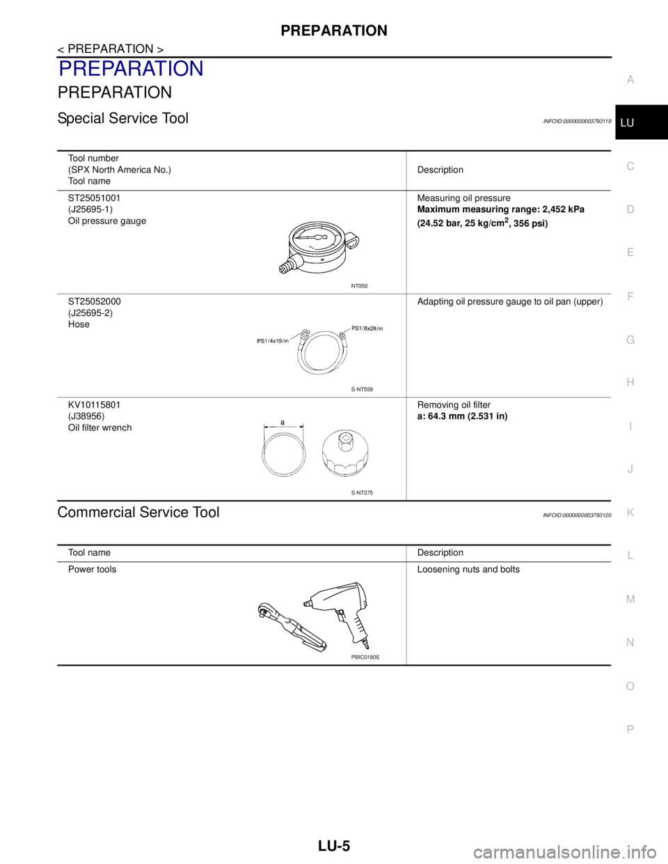
Special Service ToolINFOID:0000000003793119
Commercial Service ToolINFOID:0000000003793120
Tool number
(SPX North America No.)
Tool nameDescription
ST25051001
(J25695-1)
Oil pressure gaugeMeasuring oil pressure
Maximum measuring range: 2,452 kPa
(24.52 bar, 25 kg/cm
2, 356 psi)
ST25052000
(J25695-2)
HoseAdapting oil pressure gauge to oil pan (upper)
KV10115801
(J38956)
Oil filter wrenchRemoving oil filter
a: 64.3 mm (2.531 in)
NT050
S-NT559
S-NT375
Tool nameDescription
Power toolsLoosening nuts and bolts
PBIC0190E
Page 3178 of 5121
LU-6
< PREPARATION >
PREPARATION
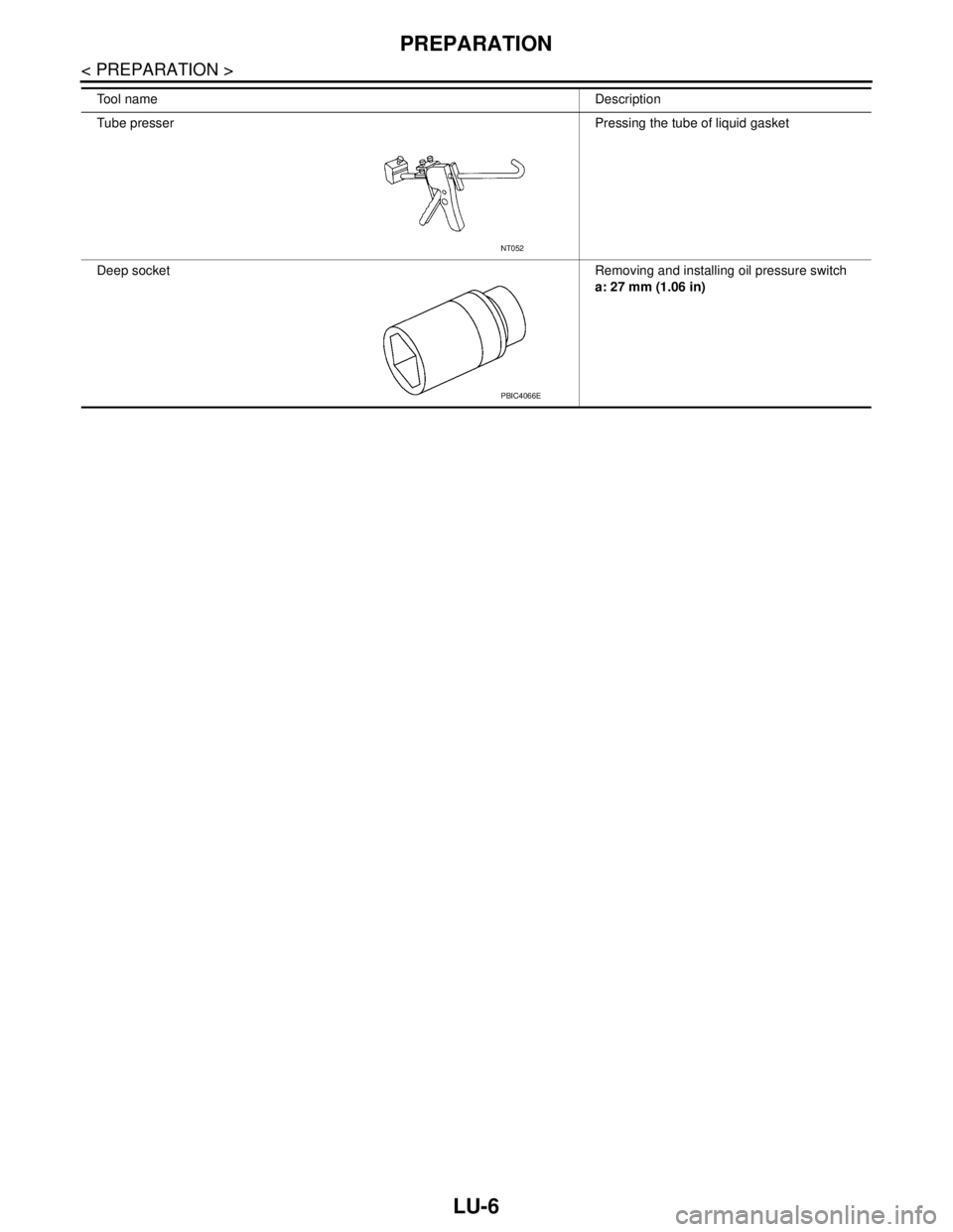
Tube presser Pressing the tube of liquid gasket
Deep socketRemoving and installing oil pressure switch
a: 27 mm (1.06 in) Tool nameDescription
NT052
PBIC4066E
Page 3179 of 5121
ENGINE OIL
LU-7
< ON-VEHICLE MAINTENANCE >
C
D
E
F
G
H
I
J
K
L
MA
LU
N
P O
ON-VEHICLE MAINTENANCE
ENGINE OIL
InspectionINFOID:0000000003793121
ENGINE OIL LEVEL
NOTE:
Before starting engine, put vehicle horizontally and check the engine oil level. If engine is already started, stop
it and allow 10 minutes before checking.
1. Pull out oil level gauge and wipe it clean.
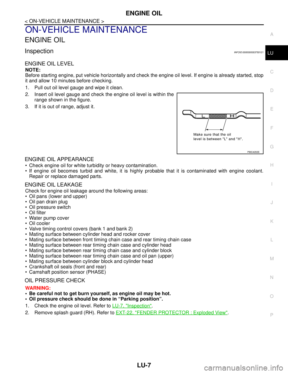
2. Insert oil level gauge and check the engine oil level is within the
range shown in the figure.
3. If it is out of range, adjust it.
ENGINE OIL APPEARANCE
Check engine oil for white turbidity or heavy contamination.
If engine oil becomes turbid and white, it is highly probable that it is contaminated with engine coolant.
Repair or replace damaged parts.
ENGINE OIL LEAKAGE
Check for engine oil leakage around the following areas:
Oil pans (lower and upper)
Oil pan drain plug
Oil pressure switch
Oil filter
Water pump cover
Oil cooler
Valve timing control covers (bank 1 and bank 2)
Mating surface between cylinder head and rocker cover
Mating surface between front timing chain case and rear timing chain case
Mating surface between rear timing chain case and cylinder head
Mating surface between rear timing chain case and cylinder block
Mating surface between rear timing chain case and oil pan (upper)
Mating surface between cylinder block and cylinder head
Crankshaft oil seals (front and rear)
Camshaft position sensor (PHASE)
OIL PRESSURE CHECK
WARNING:
• Be careful not to get burn yourself, as engine oil may be hot.
Oil pressure check should be done in “Parking position”.
1. Check the engine oil level. Refer to LU-7, "
Inspection".
2. Remove splash guard (RH). Refer to EXT-22, "
FENDER PROTECTOR : Exploded View".
PBIC4202E
Page 3180 of 5121
LU-8
< ON-VEHICLE MAINTENANCE >
ENGINE OIL
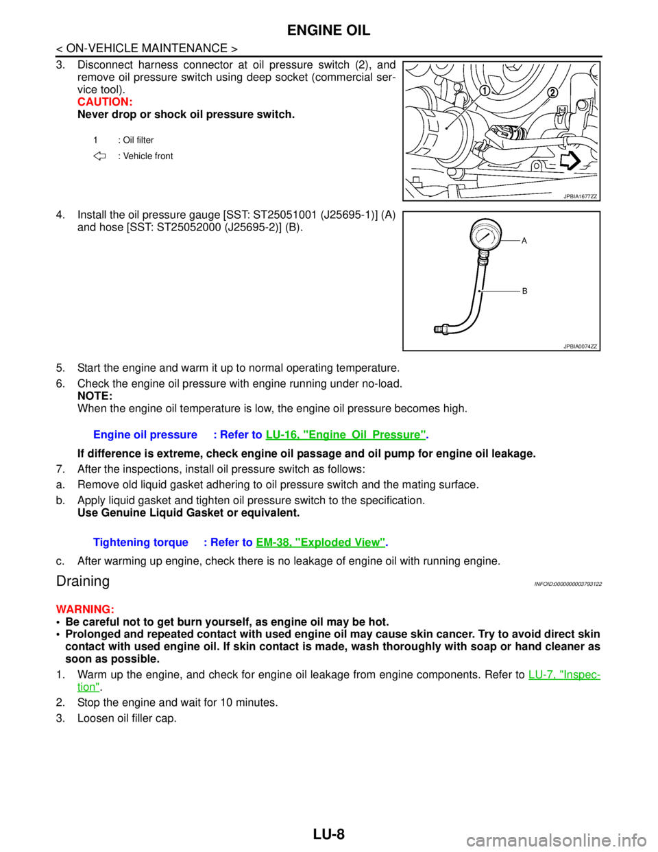
3. Disconnect harness connector at oil pressure switch (2), and
remove oil pressure switch using deep socket (commercial ser-
vice tool).
CAUTION:
Never drop or shock oil pressure switch.
4. Install the oil pressure gauge [SST: ST25051001 (J25695-1)] (A)
and hose [SST: ST25052000 (J25695-2)] (B).
5. Start the engine and warm it up to normal operating temperature.
6. Check the engine oil pressure with engine running under no-load.
NOTE:
When the engine oil temperature is low, the engine oil pressure becomes high.
If difference is extreme, check engine oil passage and oil pump for engine oil leakage.
7. After the inspections, install oil pressure switch as follows:
a. Remove old liquid gasket adhering to oil pressure switch and the mating surface.
b. Apply liquid gasket and tighten oil pressure switch to the specification.
Use Genuine Liquid Gasket or equivalent.
c. After warming up engine, check there is no leakage of engine oil with running engine.
DrainingINFOID:0000000003793122
WARNING:
Be careful not to get burn yourself, as engine oil may be hot.
Prolonged and repeated contact with used engine oil may cause skin cancer. Try to avoid direct skin
contact with used engine oil. If skin contact is made, wash thoroughly with soap or hand cleaner as
soon as possible.
1. Warm up the engine, and check for engine oil leakage from engine components. Refer to LU-7, "
Inspec-
tion".
2. Stop the engine and wait for 10 minutes.
3. Loosen oil filler cap.
1 : Oil filter
: Vehicle front
JPBIA1677ZZ
JPBIA0074ZZ
Engine oil pressure : Refer to LU-16, "EngineOilPressure".
Tightening torque : Refer to EM-38, "
Exploded View".