NISSAN TEANA 2008 Service Manual
Manufacturer: NISSAN, Model Year: 2008, Model line: TEANA, Model: NISSAN TEANA 2008Pages: 5121, PDF Size: 69.03 MB
Page 811 of 5121
![NISSAN TEANA 2008 Service Manual AV
TEL ANTENNA
AV-667
< ON-VEHICLE REPAIR >[BOSE AUDIO WITH NAVIGATION]
C
D
E
F
G
H
I
J
K
L
MB A
O
P
TEL ANTENNA
Harness LayoutINFOID:0000000003766014
JPNIA1054GB NISSAN TEANA 2008 Service Manual AV
TEL ANTENNA
AV-667
< ON-VEHICLE REPAIR >[BOSE AUDIO WITH NAVIGATION]
C
D
E
F
G
H
I
J
K
L
MB A
O
P
TEL ANTENNA
Harness LayoutINFOID:0000000003766014
JPNIA1054GB](/img/5/57391/w960_57391-810.png)
AV
TEL ANTENNA
AV-667
< ON-VEHICLE REPAIR >[BOSE AUDIO WITH NAVIGATION]
C
D
E
F
G
H
I
J
K
L
MB A
O
P
TEL ANTENNA
Harness LayoutINFOID:0000000003766014
JPNIA1054GB
Page 812 of 5121
![NISSAN TEANA 2008 Service Manual AV-668
< ON-VEHICLE REPAIR >[BOSE AUDIO WITH NAVIGATION]
TEL ANTENNA
Exploded View
INFOID:0000000003766015
Removal and InstallationINFOID:0000000003766016
REMOVAL
1. Remove rear parcel shelf finisher. NISSAN TEANA 2008 Service Manual AV-668
< ON-VEHICLE REPAIR >[BOSE AUDIO WITH NAVIGATION]
TEL ANTENNA
Exploded View
INFOID:0000000003766015
Removal and InstallationINFOID:0000000003766016
REMOVAL
1. Remove rear parcel shelf finisher.](/img/5/57391/w960_57391-811.png)
AV-668
< ON-VEHICLE REPAIR >[BOSE AUDIO WITH NAVIGATION]
TEL ANTENNA
Exploded View
INFOID:0000000003766015
Removal and InstallationINFOID:0000000003766016
REMOVAL
1. Remove rear parcel shelf finisher. Refer to INT-43, "Removal and Installation".
2. Remove trunk front finisher. Refer toINT-57, "
Removal and Installation".
3. Remove TEL antenna mounting nit, disconnect the TEL antenna connector.
4. Remove TEL antenna.
INSTALLATION
Install in the reverse order of removal.
JPNIA1053ZZ
1. TEL antenna
Page 813 of 5121
![NISSAN TEANA 2008 Service Manual AV
CAMERA CONTROL UNIT
AV-669
< ON-VEHICLE REPAIR >[BOSE AUDIO WITH NAVIGATION]
C
D
E
F
G
H
I
J
K
L
MB A
O
P
CAMERA CONTROL UNIT
Exploded ViewINFOID:0000000003766017
Removal and InstallationINFOID:000 NISSAN TEANA 2008 Service Manual AV
CAMERA CONTROL UNIT
AV-669
< ON-VEHICLE REPAIR >[BOSE AUDIO WITH NAVIGATION]
C
D
E
F
G
H
I
J
K
L
MB A
O
P
CAMERA CONTROL UNIT
Exploded ViewINFOID:0000000003766017
Removal and InstallationINFOID:000](/img/5/57391/w960_57391-812.png)
AV
CAMERA CONTROL UNIT
AV-669
< ON-VEHICLE REPAIR >[BOSE AUDIO WITH NAVIGATION]
C
D
E
F
G
H
I
J
K
L
MB A
O
P
CAMERA CONTROL UNIT
Exploded ViewINFOID:0000000003766017
Removal and InstallationINFOID:0000000003766018
REMOVAL
1. Remove rear wheelhouse finisher RH. Refer to INT-57, "Removal and Installation".
2. Remove camera control unit mounting screws, disconnect the camera control unit connector.
3. Remove camera control unit.
INSTALLATION
1. Installation is the reverse order of removal.
2. Perform predicted course line center position adjustment. Refer to AV-400, "
PREDICTED COURSE LINE
CENTER POSITION ADJUSTMENT : Special Repair Requirement".
JPNIA1049ZZ
1. Camera control unit
Page 814 of 5121
![NISSAN TEANA 2008 Service Manual AV-670
< ON-VEHICLE REPAIR >[BOSE AUDIO WITH NAVIGATION]
REAR VIEW CAMERA
REAR VIEW CAMERA
Exploded ViewINFOID:0000000003766021
DISASSEMBLY
Removal and InstallationINFOID:0000000003766022
REMOVAL
1. R NISSAN TEANA 2008 Service Manual AV-670
< ON-VEHICLE REPAIR >[BOSE AUDIO WITH NAVIGATION]
REAR VIEW CAMERA
REAR VIEW CAMERA
Exploded ViewINFOID:0000000003766021
DISASSEMBLY
Removal and InstallationINFOID:0000000003766022
REMOVAL
1. R](/img/5/57391/w960_57391-813.png)
AV-670
< ON-VEHICLE REPAIR >[BOSE AUDIO WITH NAVIGATION]
REAR VIEW CAMERA
REAR VIEW CAMERA
Exploded ViewINFOID:0000000003766021
DISASSEMBLY
Removal and InstallationINFOID:0000000003766022
REMOVAL
1. Remove trunk lid finisher inner. Refer to INT-59, "Removal and Installation".
2. Remove trunk lid finisher. Refer to EXT-38, "
Removal and Installation".
3. Remove rear view camera mounting clip, disconnect the rear view camera connector.
4. Remove rear view camera.
INSTALLATION
1. Installation is the reverse order of removal.
AdjustmentINFOID:0000000003901754
Adjust the guide line position if the guide line position is shifted after installing the rear view camera.
1. Draw lines on rearward area of the vehicle passing through the
following points: 200 mm (7.87 in) from both sides of the vehicle,
and 0.5 m (1.64 ft), 1.0 m (3.28 ft) from the rear end of the
bumper.
2. Set into “Adjust offset of rear view camera” mode of Confirma-
tion / Adjustment mode.
JPNIA1050ZZ
1. Rear view camera
2. Seal
Refer to GI-4, "
Components" for symbols in the figure.
SKIB3691E
Page 815 of 5121
![NISSAN TEANA 2008 Service Manual AV
REAR VIEW CAMERA
AV-671
< ON-VEHICLE REPAIR >[BOSE AUDIO WITH NAVIGATION]
C
D
E
F
G
H
I
J
K
L
MB A
O
P
3. Rotate the center dial, and then select the guiding line pattern so
that its angle is align NISSAN TEANA 2008 Service Manual AV
REAR VIEW CAMERA
AV-671
< ON-VEHICLE REPAIR >[BOSE AUDIO WITH NAVIGATION]
C
D
E
F
G
H
I
J
K
L
MB A
O
P
3. Rotate the center dial, and then select the guiding line pattern so
that its angle is align](/img/5/57391/w960_57391-814.png)
AV
REAR VIEW CAMERA
AV-671
< ON-VEHICLE REPAIR >[BOSE AUDIO WITH NAVIGATION]
C
D
E
F
G
H
I
J
K
L
MB A
O
P
3. Rotate the center dial, and then select the guiding line pattern so
that its angle is aligned with the correction line of the rear of the
vehicle.
4. Fine adjust the guiding line so that its position is aligned to the
correction line by pressing the up/down/left/right switches.
Pressing “ENTER” enable the camera control unit to memory
the adjusted guiding line position.
CAUTION:
Never operate other function such as pressing BACK while writing index data.
If Confirmation/Adjustment mode does not function in the above procedure, perform one of the
following service to adjust the index again.
Remove battery for five min. Then reconnect battery.
Remove camera control unit connector for five min. Then reconnect camera control unit connec-
tor.Selected pattern : 7
Up/Down adjustment range : −20 – 20
Left/Right adjustment range : −20 – 20
SKIB3689E
Page 816 of 5121
![NISSAN TEANA 2008 Service Manual AV-672
< ON-VEHICLE REPAIR >[BOSE AUDIO WITH NAVIGATION]
STEERING ANGLE SENSOR
STEERING ANGLE SENSOR
Exploded ViewINFOID:0000000003766035
REMOVAL
Refer to SR-9, "Exploded View".
DISASSEMBLY
Removal an NISSAN TEANA 2008 Service Manual AV-672
< ON-VEHICLE REPAIR >[BOSE AUDIO WITH NAVIGATION]
STEERING ANGLE SENSOR
STEERING ANGLE SENSOR
Exploded ViewINFOID:0000000003766035
REMOVAL
Refer to SR-9, "Exploded View".
DISASSEMBLY
Removal an](/img/5/57391/w960_57391-815.png)
AV-672
< ON-VEHICLE REPAIR >[BOSE AUDIO WITH NAVIGATION]
STEERING ANGLE SENSOR
STEERING ANGLE SENSOR
Exploded ViewINFOID:0000000003766035
REMOVAL
Refer to SR-9, "Exploded View".
DISASSEMBLY
Removal and InstallationINFOID:0000000003766036
REMOVAL
1. Remove spiral cable.
2. Remove steering angle sensor mounting screws.
3. Remove steering angle sensor.
INSTALLATION
Installation is the reverse order of removal.
JSNIA0135ZZ
1. Spiral cable
2. Steering angle sensor
Page 817 of 5121
![NISSAN TEANA 2008 Service Manual AV
ANTENNA FEEDER (RADIO)
AV-673
< ON-VEHICLE REPAIR >[BOSE AUDIO WITH NAVIGATION]
C
D
E
F
G
H
I
J
K
L
MB A
O
P
ANTENNA FEEDER (RADIO)
Harness LayoutINFOID:0000000003766037
JPNIA1054GB NISSAN TEANA 2008 Service Manual AV
ANTENNA FEEDER (RADIO)
AV-673
< ON-VEHICLE REPAIR >[BOSE AUDIO WITH NAVIGATION]
C
D
E
F
G
H
I
J
K
L
MB A
O
P
ANTENNA FEEDER (RADIO)
Harness LayoutINFOID:0000000003766037
JPNIA1054GB](/img/5/57391/w960_57391-816.png)
AV
ANTENNA FEEDER (RADIO)
AV-673
< ON-VEHICLE REPAIR >[BOSE AUDIO WITH NAVIGATION]
C
D
E
F
G
H
I
J
K
L
MB A
O
P
ANTENNA FEEDER (RADIO)
Harness LayoutINFOID:0000000003766037
JPNIA1054GB
Page 818 of 5121

BCS
BCS-1
ELECTRICAL & POWER CONTROL
C
D
E
F
G
H
I
J
K
L B
SECTION BCS
A
O
P N
CONTENTS
BODY CONTROL SYSTEM
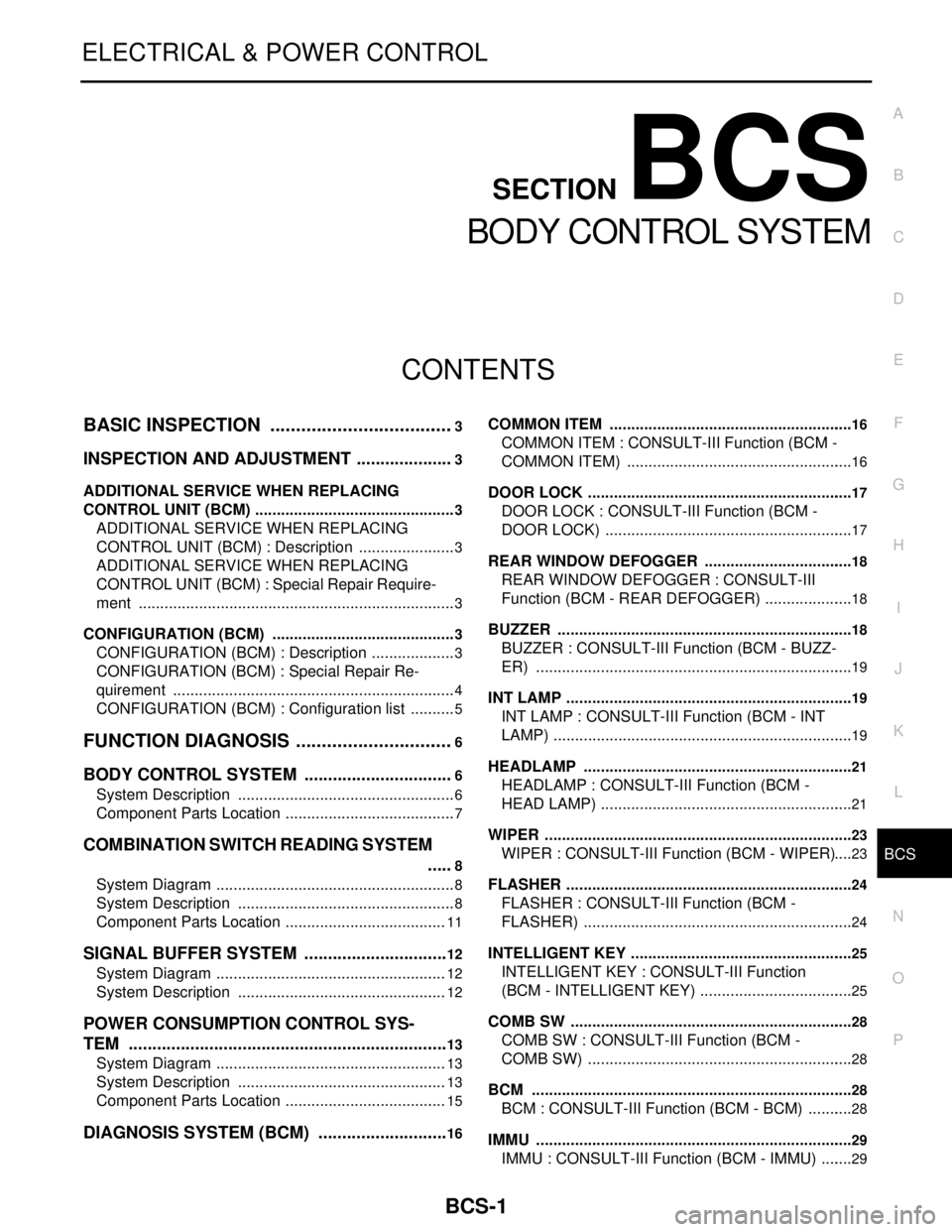
BASIC INSPECTION ....................................3
INSPECTION AND ADJUSTMENT .....................3
ADDITIONAL SERVICE WHEN REPLACING
CONTROL UNIT (BCM) ...............................................
3
ADDITIONAL SERVICE WHEN REPLACING
CONTROL UNIT (BCM) : Description .......................
3
ADDITIONAL SERVICE WHEN REPLACING
CONTROL UNIT (BCM) : Special Repair Require-
ment ..........................................................................
3
CONFIGURATION (BCM) ...........................................3
CONFIGURATION (BCM) : Description ....................3
CONFIGURATION (BCM) : Special Repair Re-
quirement ..................................................................
4
CONFIGURATION (BCM) : Configuration list ...........5
FUNCTION DIAGNOSIS ...............................6
BODY CONTROL SYSTEM ................................6
System Description ...................................................6
Component Parts Location ........................................7
COMBINATION SWITCH READING SYSTEM
.....
8
System Diagram ........................................................8
System Description ...................................................8
Component Parts Location ......................................11
SIGNAL BUFFER SYSTEM ...............................12
System Diagram ......................................................12
System Description .................................................12
POWER CONSUMPTION CONTROL SYS-
TEM ....................................................................
13
System Diagram ......................................................13
System Description .................................................13
Component Parts Location ......................................15
DIAGNOSIS SYSTEM (BCM) ............................16
COMMON ITEM .........................................................16
COMMON ITEM : CONSULT-III Function (BCM -
COMMON ITEM) .....................................................
16
DOOR LOCK ..............................................................17
DOOR LOCK : CONSULT-III Function (BCM -
DOOR LOCK) ..........................................................
17
REAR WINDOW DEFOGGER ...................................18
REAR WINDOW DEFOGGER : CONSULT-III
Function (BCM - REAR DEFOGGER) .....................
18
BUZZER .....................................................................18
BUZZER : CONSULT-III Function (BCM - BUZZ-
ER) ..........................................................................
19
INT LAMP ...................................................................19
INT LAMP : CONSULT-III Function (BCM - INT
LAMP) ......................................................................
19
HEADLAMP ...............................................................21
HEADLAMP : CONSULT-III Function (BCM -
HEAD LAMP) ...........................................................
21
WIPER ........................................................................23
WIPER : CONSULT-III Function (BCM - WIPER) ....23
FLASHER ...................................................................24
FLASHER : CONSULT-III Function (BCM -
FLASHER) ...............................................................
24
INTELLIGENT KEY ....................................................25
INTELLIGENT KEY : CONSULT-III Function
(BCM - INTELLIGENT KEY) ....................................
25
COMB SW ..................................................................28
COMB SW : CONSULT-III Function (BCM -
COMB SW) ..............................................................
28
BCM ...........................................................................28
BCM : CONSULT-III Function (BCM - BCM) ...........28
IMMU ..........................................................................29
IMMU : CONSULT-III Function (BCM - IMMU) ........29
Page 819 of 5121

BCS-2
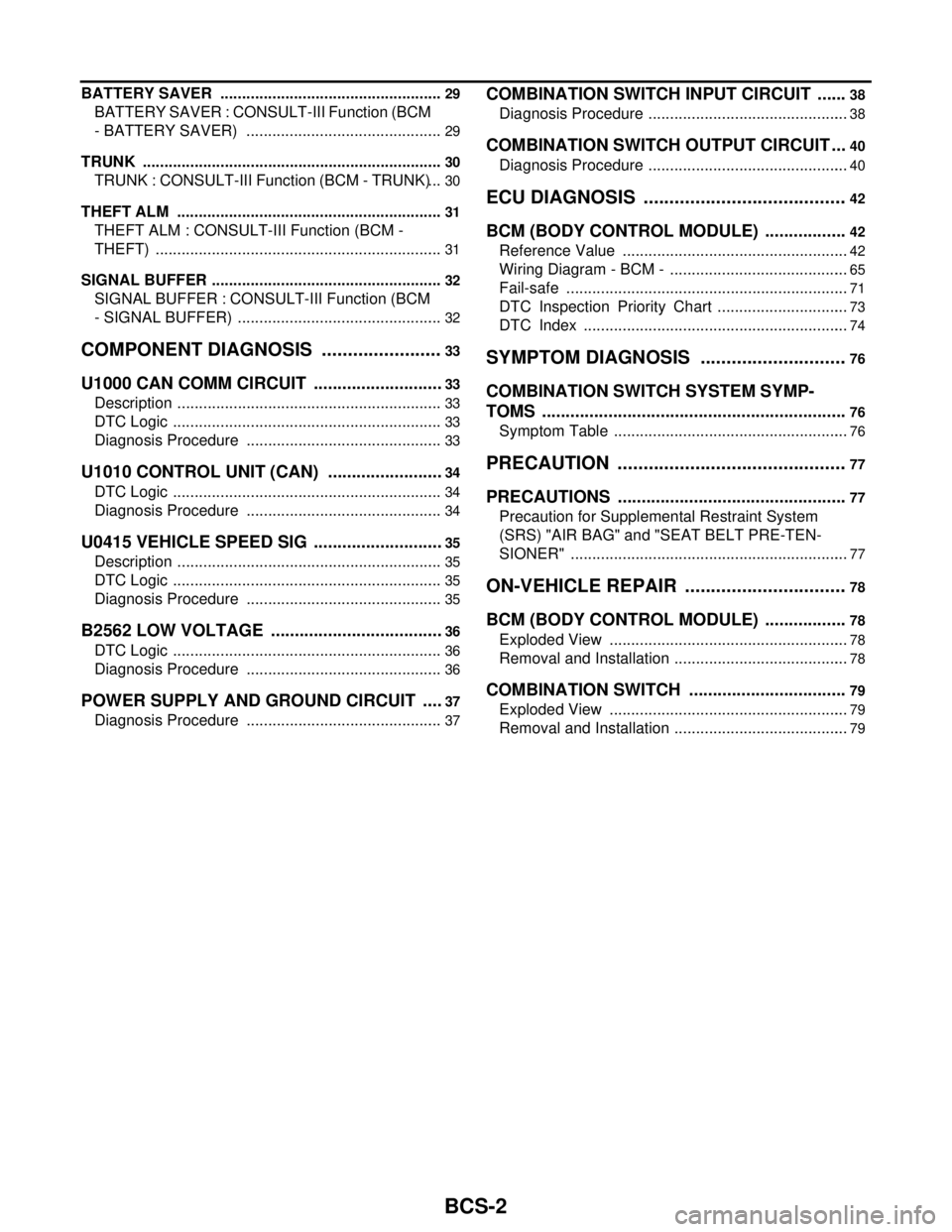
BATTERY SAVER ....................................................29
BATTERY SAVER : CONSULT-III Function (BCM
- BATTERY SAVER) ..............................................
29
TRUNK ......................................................................30
TRUNK : CONSULT-III Function (BCM - TRUNK) ...30
THEFT ALM ..............................................................31
THEFT ALM : CONSULT-III Function (BCM -
THEFT) ...................................................................
31
SIGNAL BUFFER ......................................................32
SIGNAL BUFFER : CONSULT-III Function (BCM
- SIGNAL BUFFER) ................................................
32
COMPONENT DIAGNOSIS ........................33
U1000 CAN COMM CIRCUIT ............................33
Description ..............................................................33
DTC Logic ...............................................................33
Diagnosis Procedure ..............................................33
U1010 CONTROL UNIT (CAN) .........................34
DTC Logic ...............................................................34
Diagnosis Procedure ..............................................34
U0415 VEHICLE SPEED SIG ............................35
Description ..............................................................35
DTC Logic ...............................................................35
Diagnosis Procedure ..............................................35
B2562 LOW VOLTAGE .....................................36
DTC Logic ...............................................................36
Diagnosis Procedure ..............................................36
POWER SUPPLY AND GROUND CIRCUIT .....37
Diagnosis Procedure ..............................................37
COMBINATION SWITCH INPUT CIRCUIT .......38
Diagnosis Procedure ...............................................38
COMBINATION SWITCH OUTPUT CIRCUIT ...40
Diagnosis Procedure ...............................................40
ECU DIAGNOSIS .......................................42
BCM (BODY CONTROL MODULE) ..................42
Reference Value .....................................................42
Wiring Diagram - BCM - ..........................................65
Fail-safe ..................................................................71
DTC Inspection Priority Chart ...............................73
DTC Index ..............................................................74
SYMPTOM DIAGNOSIS ............................76
COMBINATION SWITCH SYSTEM SYMP-
TOMS .................................................................
76
Symptom Table .......................................................76
PRECAUTION ............................................77
PRECAUTIONS .................................................77
Precaution for Supplemental Restraint System
(SRS) "AIR BAG" and "SEAT BELT PRE-TEN-
SIONER" .................................................................
77
ON-VEHICLE REPAIR ...............................78
BCM (BODY CONTROL MODULE) ..................78
Exploded View ........................................................78
Removal and Installation .........................................78
COMBINATION SWITCH ..................................79
Exploded View ........................................................79
Removal and Installation .........................................79
Page 820 of 5121

BCS
INSPECTION AND ADJUSTMENT
BCS-3
< BASIC INSPECTION >
C
D
E
F
G
H
I
J
K
L B A
O
P N
BASIC INSPECTION
INSPECTION AND ADJUSTMENT
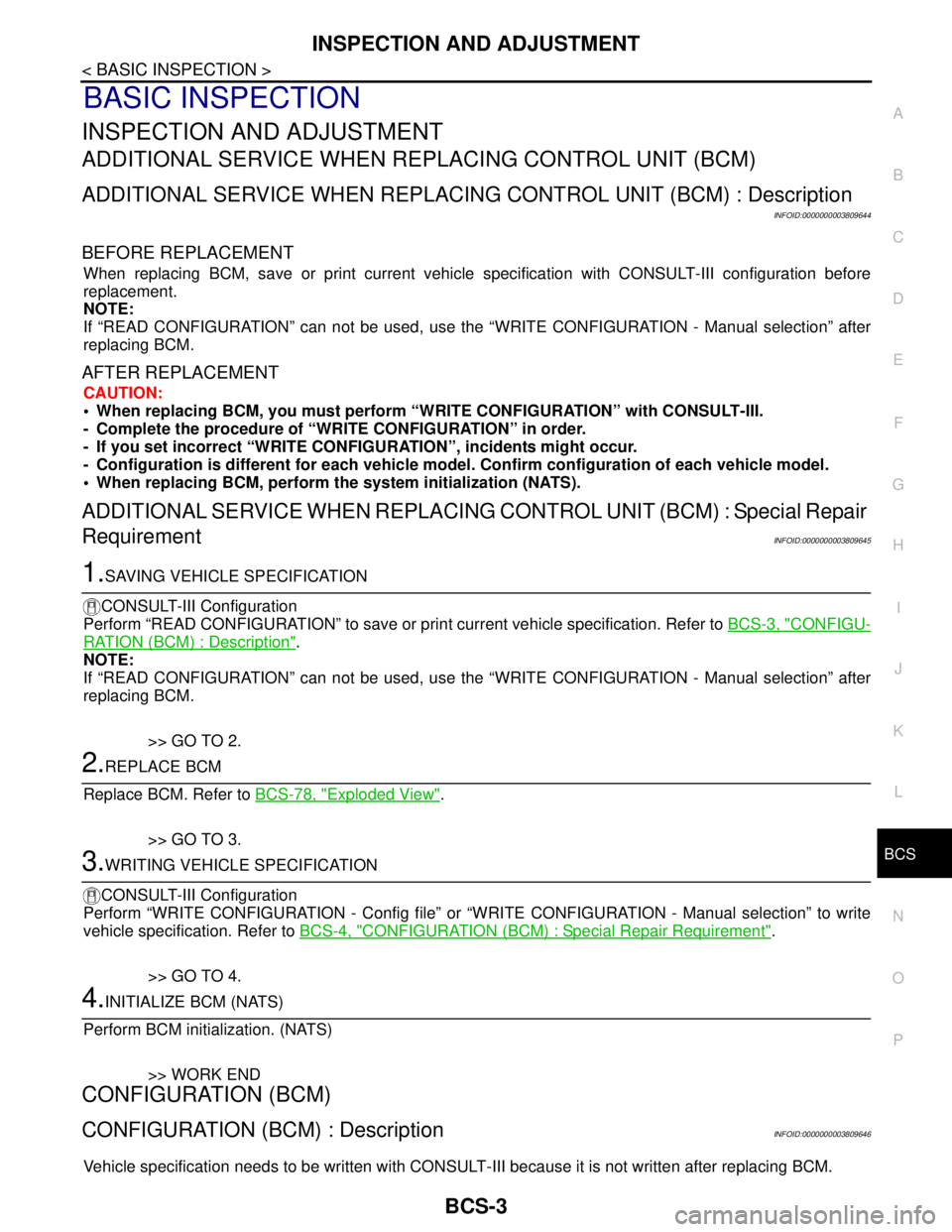
ADDITIONAL SERVICE WHEN REPLACING CONTROL UNIT (BCM)
ADDITIONAL SERVICE WHEN REPLACING CONTROL UNIT (BCM) : Description
INFOID:0000000003809644
BEFORE REPLACEMENT
When replacing BCM, save or print current vehicle specification with CONSULT-III configuration before
replacement.
NOTE:
If “READ CONFIGURATION” can not be used, use the “WRITE CONFIGURATION - Manual selection” after
replacing BCM.
AFTER REPLACEMENT
CAUTION:
• When replacing BCM, you must perform “WRITE CONFIGURATION” with CONSULT-III.
- Complete the procedure of “WRITE CONFIGURATION” in order.
- If you set incorrect “WRITE CONFIGURATION”, incidents might occur.
- Configuration is different for each vehicle model. Confirm configuration of each vehicle model.
When replacing BCM, perform the system initialization (NATS).
ADDITIONAL SERVICE WHEN REPLACING CONTROL UNIT (BCM) : Special Repair
Requirement
INFOID:0000000003809645
1.SAVING VEHICLE SPECIFICATION
CONSULT-III Configuration
Perform “READ CONFIGURATION” to save or print current vehicle specification. Refer to BCS-3, "
CONFIGU-
RATION (BCM) : Description".
NOTE:
If “READ CONFIGURATION” can not be used, use the “WRITE CONFIGURATION - Manual selection” after
replacing BCM.
>> GO TO 2.
2.REPLACE BCM
Replace BCM. Refer to BCS-78, "
Exploded View".
>> GO TO 3.
3.WRITING VEHICLE SPECIFICATION
CONSULT-III Configuration
Perform “WRITE CONFIGURATION - Config file” or “WRITE CONFIGURATION - Manual selection” to write
vehicle specification. Refer to BCS-4, "
CONFIGURATION (BCM) : Special Repair Requirement".
>> GO TO 4.
4.INITIALIZE BCM (NATS)
Perform BCM initialization. (NATS)
>> WORK END
CONFIGURATION (BCM)
CONFIGURATION (BCM) : DescriptionINFOID:0000000003809646
Vehicle specification needs to be written with CONSULT-III because it is not written after replacing BCM.