NISSAN TEANA 2008 Service Manual
Manufacturer: NISSAN, Model Year: 2008, Model line: TEANA, Model: NISSAN TEANA 2008Pages: 5121, PDF Size: 69.03 MB
Page 821 of 5121
BCS-4
< BASIC INSPECTION >
INSPECTION AND ADJUSTMENT
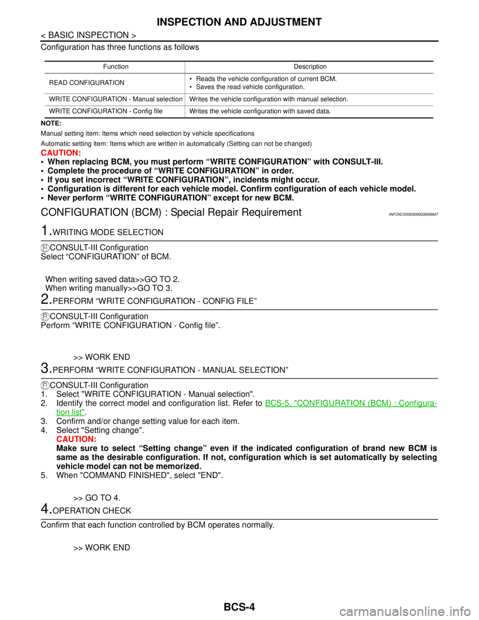
Configuration has three functions as follows
NOTE:
Manual setting item: Items which need selection by vehicle specifications
Automatic setting item: Items which are written in automatically (Setting can not be changed)
CAUTION:
When replacing BCM, you must perform “WRITE CONFIGURATION” with CONSULT-III.
Complete the procedure of “WRITE CONFIGURATION” in order.
If you set incorrect “WRITE CONFIGURATION”, incidents might occur.
Configuration is different for each vehicle model. Confirm configuration of each vehicle model.
Never perform “WRITE CONFIGURATION” except for new BCM.
CONFIGURATION (BCM) : Special Repair RequirementINFOID:0000000003809647
1.WRITING MODE SELECTION
CONSULT-III Configuration
Select “CONFIGURATION” of BCM.
When writing saved data>>GO TO 2.
When writing manually>>GO TO 3.
2.PERFORM “WRITE CONFIGURATION - CONFIG FILE”
CONSULT-III Configuration
Perform “WRITE CONFIGURATION - Config file”.
>> WORK END
3.PERFORM “WRITE CONFIGURATION - MANUAL SELECTION”
CONSULT-III Configuration
1. Select "WRITE CONFIGURATION - Manual selection".
2. Identify the correct model and configuration list. Refer to BCS-5, "
CONFIGURATION (BCM) : Configura-
tion list".
3. Confirm and/or change setting value for each item.
4. Select "Setting change".
CAUTION:
Make sure to select “Setting change” even if the indicated configuration of brand new BCM is
same as the desirable configuration. If not, configuration which is set automatically by selecting
vehicle model can not be memorized.
5. When "COMMAND FINISHED", select "END".
>> GO TO 4.
4.OPERATION CHECK
Confirm that each function controlled by BCM operates normally.
>> WORK END
Function Description
READ CONFIGURATION Reads the vehicle configuration of current BCM.
Saves the read vehicle configuration.
WRITE CONFIGURATION - Manual selection Writes the vehicle configuration with manual selection.
WRITE CONFIGURATION - Config file Writes the vehicle configuration with saved data.
Page 822 of 5121

BCS
INSPECTION AND ADJUSTMENT
BCS-5
< BASIC INSPECTION >
C
D
E
F
G
H
I
J
K
L B A
O
P N
CONFIGURATION (BCM) : Configuration listINFOID:0000000003809648
⇔: Items which confirm vehicle specificationsMANUAL SETTING ITEM
NOTE
Items Setting value
AUTO LIGHT WITH —
RR FOG LAMP WITH —
AV C/U WITH ⇔ WITHOUT WITH: With BOSE audio system
WITHOUT: Without BOSE audio system
THEFT ALM AREA MODE3 —
H/L WASHER TIME 1 WITH —
H/L WASHER TIME 2 WITH —
I-KEY WITH —
Key Fob Type MODE10 —
HANDLE LHD —
AUTO SETTING ITEM
NOTE
Items Setting value
H/L BULB DEFAULT —
FR FOG LAMP WITH —
TRANSMISSION AT with ABS —
TR CANCL SW WITHOUT —
TPMS WITHOUT —
AUTO BACK DOOR WITHOUT —
FOG LAMP BULB SINGLE BULB —
D I L M P VA R I AT M O D E 4 —
LIGHT RECOG MODE4 —
FR FOG LOGIC MODE2 —
PANIC ALM TYPE MODE2 —
HAZARD SW TYPE MODE1 —
BCM AC CONTROL MODE1 —
RAIN SENSOR WITHOUT —
FOG ON WITH AUTO LIGHT WITHOUT —
AUTO LOCK&UNLOCK FUNC WITHOUT —
DROP WIP FUNCTION WITHOUT —
SELECTIVE UNLOCK SETTING WITHOUT —
SEAT BLT WARN WITHOUT —
SPEED SNS WIP WITH —
Page 823 of 5121
BCS-6
< FUNCTION DIAGNOSIS >
BODY CONTROL SYSTEM
FUNCTION DIAGNOSIS
BODY CONTROL SYSTEM
System DescriptionINFOID:0000000003809584
OUTLINE
BCM (Body Control Module) controls the various electrical components. It inputs the information required to
the control from CAN communication and the signal received from each switch and sensor.
BCM has combination switch reading function for reading the operation status of combination switches (light,
turn signal, wiper and washer) in addition to a function for controlling the operation of various electrical com-
ponents. It also has the signal transmission function as the passed point of signal and the power saving con-
trol function that reduces the power consumption with the ignition switch OFF.
BCM is equipped with the diagnosis function that performs the diagnosis with CONSULT-III and various set-
tings.
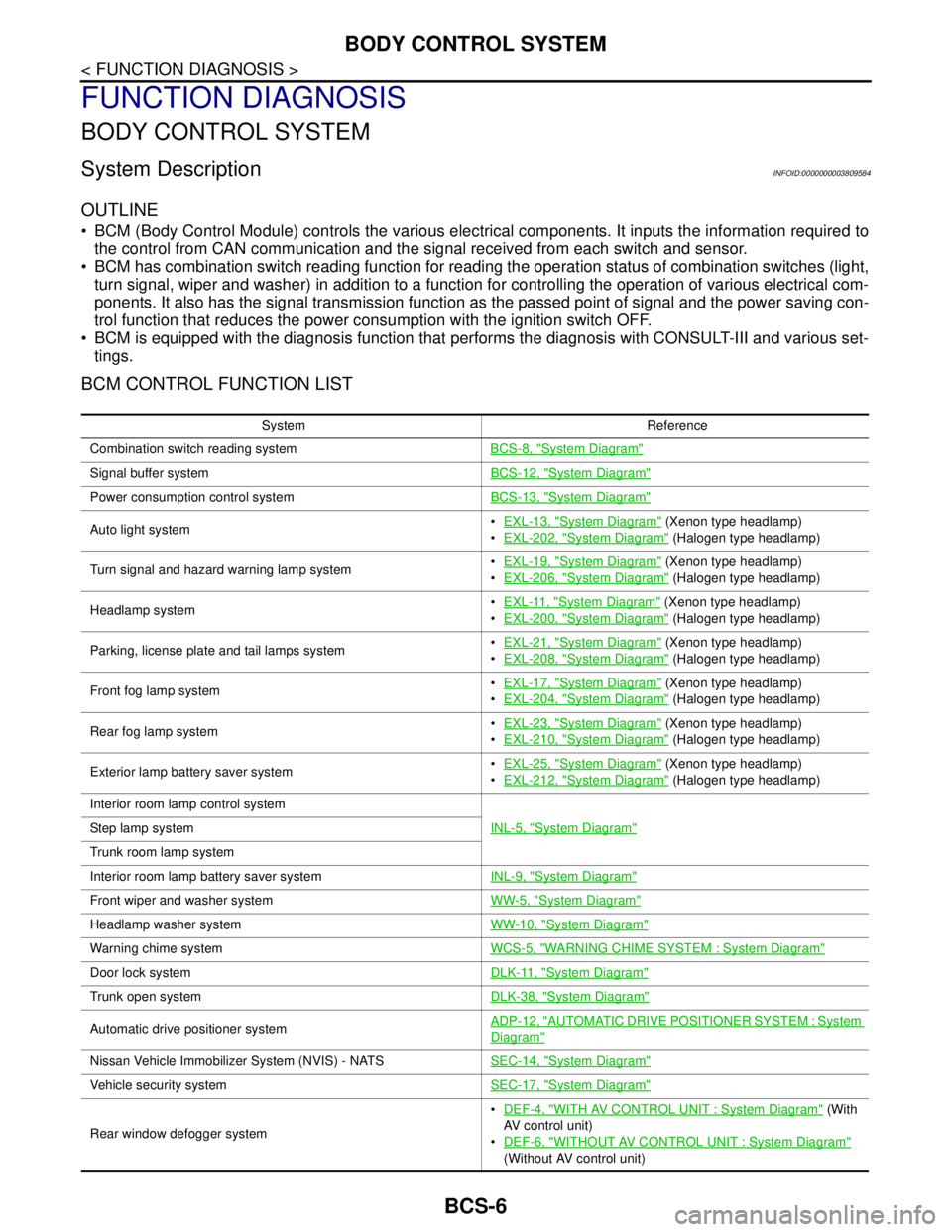
BCM CONTROL FUNCTION LIST
System Reference
Combination switch reading systemBCS-8, "
System Diagram"
Signal buffer systemBCS-12, "System Diagram"
Power consumption control systemBCS-13, "System Diagram"
Auto light systemEXL-13, "System Diagram" (Xenon type headlamp)
EXL-202, "
System Diagram" (Halogen type headlamp)
Turn signal and hazard warning lamp systemEXL-19, "
System Diagram" (Xenon type headlamp)
EXL-206, "
System Diagram" (Halogen type headlamp)
Headlamp systemEXL-11, "
System Diagram" (Xenon type headlamp)
EXL-200, "
System Diagram" (Halogen type headlamp)
Parking, license plate and tail lamps systemEXL-21, "
System Diagram" (Xenon type headlamp)
EXL-208, "
System Diagram" (Halogen type headlamp)
Front fog lamp systemEXL-17, "
System Diagram" (Xenon type headlamp)
EXL-204, "
System Diagram" (Halogen type headlamp)
Rear fog lamp systemEXL-23, "
System Diagram" (Xenon type headlamp)
EXL-210, "
System Diagram" (Halogen type headlamp)
Exterior lamp battery saver systemEXL-25, "
System Diagram" (Xenon type headlamp)
EXL-212, "
System Diagram" (Halogen type headlamp)
Interior room lamp control system
INL-5, "
System Diagram"Step lamp system
Trunk room lamp system
Interior room lamp battery saver systemINL-9, "
System Diagram"
Front wiper and washer systemWW-5, "System Diagram"
Headlamp washer systemWW-10, "System Diagram"
Warning chime systemWCS-5, "WARNING CHIME SYSTEM : System Diagram"
Door lock systemDLK-11, "System Diagram"
Trunk open systemDLK-38, "System Diagram"
Automatic drive positioner systemADP-12, "AUTOMATIC DRIVE POSITIONER SYSTEM : System
Diagram"
Nissan Vehicle Immobilizer System (NVIS) - NATSSEC-14, "System Diagram"
Vehicle security systemSEC-17, "System Diagram"
Rear window defogger systemDEF-4, "
WITH AV CONTROL UNIT : System Diagram" (With
AV control unit)
DEF-6, "
WITHOUT AV CONTROL UNIT : System Diagram"
(Without AV control unit)
Page 824 of 5121

BCS
BODY CONTROL SYSTEM
BCS-7
< FUNCTION DIAGNOSIS >
C
D
E
F
G
H
I
J
K
L B A
O
P N
Component Parts LocationINFOID:0000000003809585
Intelligent Key system/engine start systemDoor lock function
DLK-14, "INTELLIGENT KEY SYSTEM : System Diagram"
Trunk open function
Remote keyless entry
function
Key reminder function
Warning function
Engine start function
Power window systemPWC-7, "
SystemDiagram"
System Reference
1. BCM
A. Behind of combination meter
JPMIA1040ZZ
Page 825 of 5121
BCS-8
< FUNCTION DIAGNOSIS >
COMBINATION SWITCH READING SYSTEM
COMBINATION SWITCH READING SYSTEM
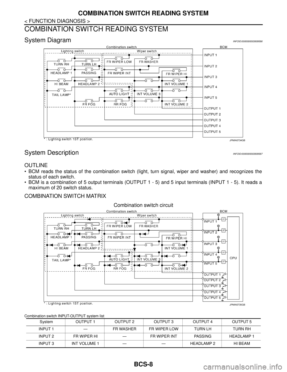
System DiagramINFOID:0000000003809586
System DescriptionINFOID:0000000003809587
OUTLINE
BCM reads the status of the combination switch (light, turn signal, wiper and washer) and recognizes the
status of each switch.
BCM is a combination of 5 output terminals (OUTPUT 1 - 5) and 5 input terminals (INPUT 1 - 5). It reads a
maximum of 20 switch status.
COMBINATION SWITCH MATRIX
Combination switch circuit
Combination switch INPUT-OUTPUT system list
JPMIA0734GB
System OUTPUT 1 OUTPUT 2 OUTPUT 3 OUTPUT 4 OUTPUT 5
INPUT 1 — FR WASHER FR WIPER LOW TURN LH TURN RH
INPUT 2 FR WIPER HI — FR WIPER INT PASSING HEADLAMP 1
INPUT 3 INT VOLUME 1 — — HEADLAMP 2 HI BEAM
JPMIA0735GB
Page 826 of 5121
BCS
COMBINATION SWITCH READING SYSTEM
BCS-9
< FUNCTION DIAGNOSIS >
C
D
E
F
G
H
I
J
K
L B A
O
P N
NOTE:
Headlamp has a dual system switch.
COMBINATION SWITCH READING FUNCTION
Description
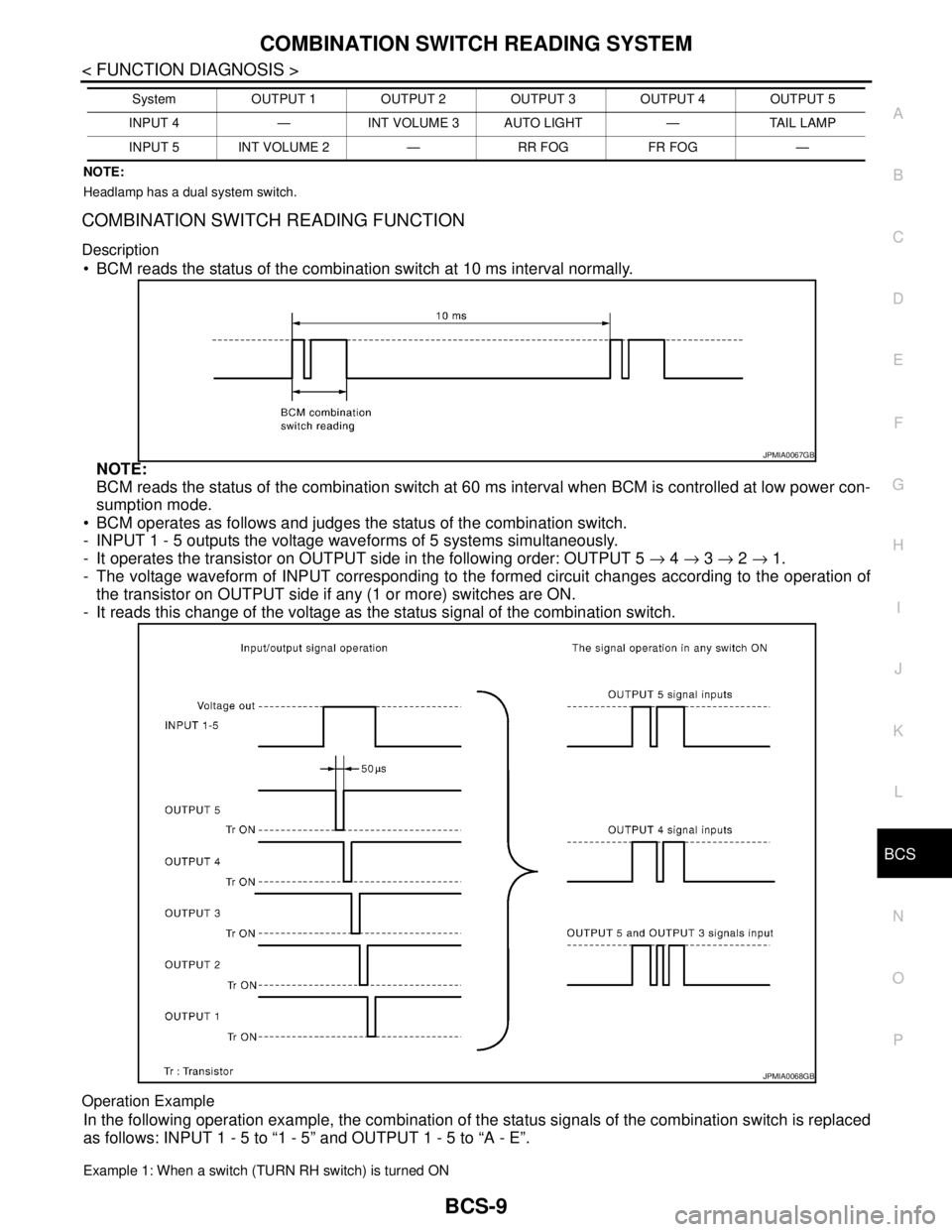
BCM reads the status of the combination switch at 10 ms interval normally.
NOTE:
BCM reads the status of the combination switch at 60 ms interval when BCM is controlled at low power con-
sumption mode.
BCM operates as follows and judges the status of the combination switch.
- INPUT 1 - 5 outputs the voltage waveforms of 5 systems simultaneously.
- It operates the transistor on OUTPUT side in the following order: OUTPUT 5 → 4 → 3 → 2 → 1.
- The voltage waveform of INPUT corresponding to the formed circuit changes according to the operation of
the transistor on OUTPUT side if any (1 or more) switches are ON.
- It reads this change of the voltage as the status signal of the combination switch.
Operation Example
In the following operation example, the combination of the status signals of the combination switch is replaced
as follows: INPUT 1 - 5 to “1 - 5” and OUTPUT 1 - 5 to “A - E”.
Example 1: When a switch (TURN RH switch) is turned ON
INPUT 4 — INT VOLUME 3 AUTO LIGHT — TAIL LAMP
INPUT 5 INT VOLUME 2 — RR FOG FR FOG —System OUTPUT 1 OUTPUT 2 OUTPUT 3 OUTPUT 4 OUTPUT 5
JPMIA0067GB
JPMIA0068GB
Page 827 of 5121

BCS-10
< FUNCTION DIAGNOSIS >
COMBINATION SWITCH READING SYSTEM
The circuit between INPUT 1 and OUTPUT 5 is formed when the TURN RH switch is turned ON.
BCM detects the combination switch status signal “1E” when the signal of OUTPUT 5 is input to INPUT 1.
BCM judges that the TURN RH switch is ON when the signal “1E” is detected.
Example 2: When some switches (turn RH switch, front wiper LO switch) are turned ON
The circuits between INPUT 1 and OUTPUT 5 and between INPUT 1 and OUTPUT 3 are formed when the
TURN RH switch and FR WIPER LOW switch are turned ON.
BCM detects the combination switch status signal “1CE” when the signals of OUTPUT 3 and OUTPUT 5 are
input to INPUT 1.
BCM judges that the TURN RH switch and FR WIPER LOW switch are ON when the signal “1CE” is
detected.
WIPER INTERMITTENT DIAL POSITION SETTING (FRONT WIPER INTERMITTENT OPERATION)
BCM judges the wiper intermittent dial 1 - 7 by the status of INT VOLUME 1, 2 and 3 switches.
JPMIA0736GB
JPMIA0737GB
Page 828 of 5121

BCS
COMBINATION SWITCH READING SYSTEM
BCS-11
< FUNCTION DIAGNOSIS >
C
D
E
F
G
H
I
J
K
L B A
O
P N
Component Parts LocationINFOID:0000000003809588
Wiper intermittent
dial positionIntermittent
operation delay
intervalINT VOLUME switch ON/OFF status
INT VOLUME 1 switch INT VOLUME 2 switch INT VOLUME 3 switch
1
Short
↑
↓
LongON ON ON
2ONONOFF
3ONOFFOFF
4 OFF OFF OFF
5OFFOFFON
6OFFONON
7OFFONOFF
1. Combination switch 2. BCM
A. Behind of combination meter
JPMIA1041ZZ
Page 829 of 5121
BCS-12
< FUNCTION DIAGNOSIS >
SIGNAL BUFFER SYSTEM
SIGNAL BUFFER SYSTEM
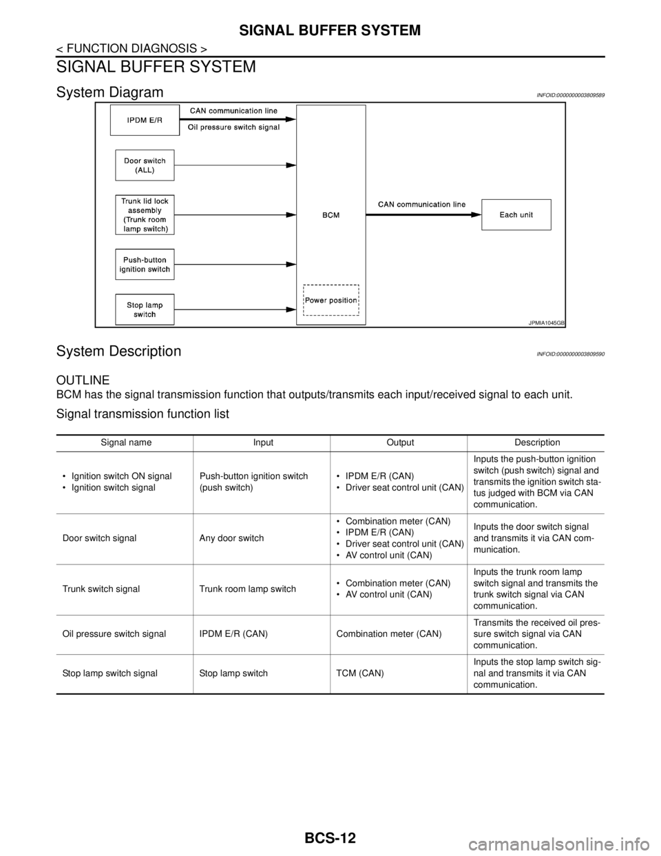
System DiagramINFOID:0000000003809589
System DescriptionINFOID:0000000003809590
OUTLINE
BCM has the signal transmission function that outputs/transmits each input/received signal to each unit.
Signal transmission function list
JPMIA1045GB
Signal name Input Output Description
Ignition switch ON signal
Ignition switch signalPush-button ignition switch
(push switch) IPDM E/R (CAN)
Driver seat control unit (CAN)Inputs the push-button ignition
switch (push switch) signal and
transmits the ignition switch sta-
tus judged with BCM via CAN
communication.
Door switch signal Any door switch Combination meter (CAN)
IPDM E/R (CAN)
Driver seat control unit (CAN)
AV control unit (CAN)Inputs the door switch signal
and transmits it via CAN com-
munication.
Trunk switch signal Trunk room lamp switch Combination meter (CAN)
AV control unit (CAN)Inputs the trunk room lamp
switch signal and transmits the
trunk switch signal via CAN
communication.
Oil pressure switch signal IPDM E/R (CAN) Combination meter (CAN)Transmits the received oil pres-
sure switch signal via CAN
communication.
Stop lamp switch signal Stop lamp switch TCM (CAN)Inputs the stop lamp switch sig-
nal and transmits it via CAN
communication.
Page 830 of 5121

BCS
POWER CONSUMPTION CONTROL SYSTEM
BCS-13
< FUNCTION DIAGNOSIS >
C
D
E
F
G
H
I
J
K
L B A
O
P N
POWER CONSUMPTION CONTROL SYSTEM
System DiagramINFOID:0000000003809591
System DescriptionINFOID:0000000003809592
OUTLINE
BCM incorporates a power saving control function that reduces the power consumption according to the
vehicle status.
BCM switches the status (control mode) by itself with the power saving control function. It performs the sleep
request to each unit (IPDM E/R, combination meter, driver seat control unit and automatic back door control
unit) that operates with the ignition switch OFF.
Normal mode (wake-up)- CAN communication is normally performed with other units
- Each control with BCM is operating properly
CAN communication sleep mode (CAN sleep)- CAN transmission is stopped
- Control with BCM only is operating
Low power consumption mode (BCM sleep)- Low power consumption control is active
- CAN transmission is stopped
LOW POWER CONSUMPTION CONTROL WITH BCM
BCM reduces the power consumption with the following operation in the low power consumption mode.
The reading interval of the each switches changes from 10 ms interval to 60 ms interval.
Sleep mode activation
BCM receives the sleep-ready signal (ready) from IPDM E/R and combination meter via CAN communica-
tion.
BCM transmits the sleep wake up signal (sleep) to each unit when all of the CAN sleep conditions are ful-
filled.
Each unit stops the transmission of CAN communication with the sleep wake up signal. BCM is in CAN com-
munication sleep mode.
BCM is in the low power consumption mode and perform the low power consumption control when all of the
BCM sleep conditions are fulfilled with CAN sleep condition.
JPMIA1046GB