NISSAN TEANA 2008 Service Manual
Manufacturer: NISSAN, Model Year: 2008, Model line: TEANA, Model: NISSAN TEANA 2008Pages: 5121, PDF Size: 69.03 MB
Page 891 of 5121
BCS-74
< ECU DIAGNOSIS >
BCM (BODY CONTROL MODULE)
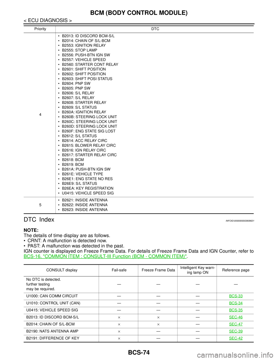
DTC Index
INFOID:0000000003809631
NOTE:
The details of time display are as follows.
CRNT: A malfunction is detected now.
PAST: A malfunction was detected in the past.
IGN counter is displayed on Freeze Frame Data. For details of Freeze Frame Data and IGN Counter, refer to
BCS-16, "
COMMON ITEM : CONSULT-III Function (BCM - COMMON ITEM)".
4 B2013: ID DISCORD BCM-S/L
B2014: CHAIN OF S/L-BCM
B2553: IGNITION RELAY
B2555: STOP LAMP
B2556: PUSH-BTN IGN SW
B2557: VEHICLE SPEED
B2560: STARTER CONT RELAY
B2601: SHIFT POSITION
B2602: SHIFT POSITION
B2603: SHIFT POSI STATUS
B2604: PNP SW
B2605: PNP SW
B2606: S/L RELAY
B2607: S/L RELAY
B2608: STARTER RELAY
B2609: S/L STATUS
B260A: IGNITION RELAY
B260B: STEERING LOCK UNIT
B260C: STEERING LOCK UNIT
B260D: STEERING LOCK UNIT
B260F: ENG STATE SIG LOST
B2612: S/L STATUS
B2614: ACC RELAY CIRC
B2615: BLOWER RELAY CIRC
B2616: IGN RELAY CIRC
B2617: STARTER RELAY CIRC
B2618: BCM
B2619: BCM
B261A: PUSH-BTN IGN SW
B261E: VEHICLE TYPE
B26E1: ENG STATE NO RES
B26E9: S/L STATUS
B26EA: KEY REGISTRATION
U0415: VEHICLE SPEED SIG
5 B2621: INSIDE ANTENNA
B2622: INSIDE ANTENNA
B2623: INSIDE ANTENNA Priority DTC
CONSULT display Fail-safe Freeze Frame DataIntelligent Key warn-
ing lamp ONReference page
No DTC is detected.
further testing
may be required.————
U1000: CAN COMM CIRCUIT — — —BCS-33
U1010: CONTROL UNIT (CAN) — — —BCS-34
U0415: VEHICLE SPEED SIG — — —BCS-35
B2013: ID DISCORD BCM-S/L××—SEC-46
B2014: CHAIN OF S/L-BCM××—SEC-47
B2190: NATS ANTENNA AMP×——SEC-39
B2191: DIFFERENCE OF KEY×——SEC-42
Page 892 of 5121
BCS
BCM (BODY CONTROL MODULE)
BCS-75
< ECU DIAGNOSIS >
C
D
E
F
G
H
I
J
K
L B A
O
P N
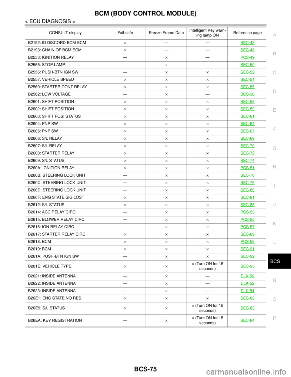
B2192: ID DISCORD BCM-ECM×——SEC-43
B2193: CHAIN OF BCM-ECM×——SEC-45
B2553: IGNITION RELAY —×—PCS-49
B2555: STOP LAMP —×—SEC-50
B2556: PUSH-BTN IGN SW —××SEC-52
B2557: VEHICLE SPEED×××SEC-54
B2560: STARTER CONT RELAY×××SEC-55
B2562: LOW VOLTAGE —×—BCS-36
B2601: SHIFT POSITION×××SEC-56
B2602: SHIFT POSITION×××SEC-59
B2603: SHIFT POSI STATUS×××SEC-61
B2604: PNP SW×××SEC-64
B2605: PNP SW×××SEC-67
B2606: S/L RELAY×××SEC-69
B2607: S/L RELAY×××SEC-70
B2608: STARTER RELAY×××SEC-72
B2609: S/L STATUS×××SEC-74
B260A: IGNITION RELAY×××PCS-51
B260B: STEERING LOCK UNIT —××SEC-78
B260C: STEERING LOCK UNIT —××SEC-79
B260D: STEERING LOCK UNIT —××SEC-80
B260F: ENG STATE SIG LOST×××SEC-81
B2612: S/L STATUS×××SEC-85
B2614: ACC RELAY CIRC —××PCS-53
B2615: BLOWER RELAY CIRC —××PCS-55
B2616: IGN RELAY CIRC —××PCS-57
B2617: STARTER RELAY CIRC×××SEC-89
B2618: BCM×××PCS-59
B2619: BCM×××SEC-91
B261A: PUSH-BTN IGN SW —××SEC-92
B261E: VEHICLE TYPE××× (Turn ON for 15
seconds)SEC-95
B2621: INSIDE ANTENNA —×—DLK-50
B2622: INSIDE ANTENNA —×—DLK-52
B2623: INSIDE ANTENNA —×—DLK-54
B26E1: ENG STATE NO RES×××SEC-82
B26E9: S/L STATUS××× (Turn ON for 15
seconds)SEC-83
B26EA: KEY REGISTRATION —×× (Turn ON for 15
seconds)SEC-84
CONSULT display Fail-safe Freeze Frame DataIntelligent Key warn-
ing lamp ONReference page
Page 893 of 5121
BCS-76
< SYMPTOM DIAGNOSIS >
COMBINATION SWITCH SYSTEM SYMPTOMS
SYMPTOM DIAGNOSIS
COMBINATION SWITCH SYSTEM SYMPTOMS
Symptom TableINFOID:0000000003809632
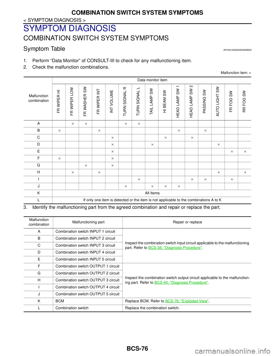
1. Perform “Data Monitor” of CONSULT-III to check for any malfunctioning item.
2. Check the malfunction combinations.
Malfunction item: ×
3. Identify the malfunctioning part from the agreed combination and repair or replace the part.
Malfunction
combinationData monitor item
FR WIPER HI
FR WIPER LOW
FR WASHER SW
FR WIPER INT
INT VOLUME
TURN SIGNAL R
TURN SIGNAL L
TAIL LAMP SW
HI BEAM SW
HEAD LAMP SW 1
HEAD LAMP SW 2
PASSING SW
AUTO LIGHT SW
FR FOG SW
RR FOG SW
A×× ××
B×× ××
C×××
D×× ×
E×××
F××
G××
H×× ××
I××××
J× ×××
K All Items
L If only one item is detected or the item is not applicable to the combinations A to K
Malfunction
combinationMalfunctioning part Repair or replace
A Combination switch INPUT 1 circuit
Inspect the combination switch input circuit applicable to the malfunctioning
part. Refer to BCS-38, "
Diagnosis Procedure". B Combination switch INPUT 2 circuit
C Combination switch INPUT 3 circuit
D Combination switch INPUT 4 circuit
E Combination switch INPUT 5 circuit
F Combination switch OUTPUT 1 circuit
Inspect the combination switch output circuit applicable to the malfunction-
ing part. Refer to BCS-40, "
Diagnosis Procedure". G Combination switch OUTPUT 2 circuit
H Combination switch OUTPUT 3 circuit
I Combination switch OUTPUT 4 circuit
J Combination switch OUTPUT 5 circuit
K BCM Replace BCM. Refer to BCS-78, "
Exploded View".
L Combination switch Replace the combination switch.
Page 894 of 5121
BCS
PRECAUTIONS
BCS-77
< PRECAUTION >
C
D
E
F
G
H
I
J
K
L B A
O
P N
PRECAUTION
PRECAUTIONS
Precaution for Supplemental Restraint System (SRS) "AIR BAG" and "SEAT BELT
PRE-TENSIONER"
INFOID:0000000003809633
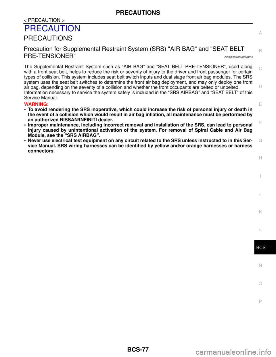
The Supplemental Restraint System such as “AIR BAG” and “SEAT BELT PRE-TENSIONER”, used along
with a front seat belt, helps to reduce the risk or severity of injury to the driver and front passenger for certain
types of collision. This system includes seat belt switch inputs and dual stage front air bag modules. The SRS
system uses the seat belt switches to determine the front air bag deployment, and may only deploy one front
air bag, depending on the severity of a collision and whether the front occupants are belted or unbelted.
Information necessary to service the system safely is included in the “SRS AIRBAG” and “SEAT BELT” of this
Service Manual.
WARNING:
To avoid rendering the SRS inoperative, which could increase the risk of personal injury or death in
the event of a collision which would result in air bag inflation, all maintenance must be performed by
an authorized NISSAN/INFINITI dealer.
Improper maintenance, including incorrect removal and installation of the SRS, can lead to personal
injury caused by unintentional activation of the system. For removal of Spiral Cable and Air Bag
Module, see the “SRS AIRBAG”.
Never use electrical test equipment on any circuit related to the SRS unless instructed to in this Ser-
vice Manual. SRS wiring harnesses can be identified by yellow and/or orange harnesses or harness
connectors.
Page 895 of 5121
BCS-78
< ON-VEHICLE REPAIR >
BCM (BODY CONTROL MODULE)
ON-VEHICLE REPAIR
BCM (BODY CONTROL MODULE)
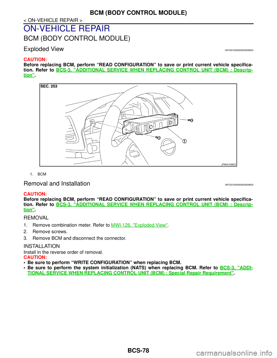
Exploded ViewINFOID:0000000003809634
CAUTION:
Before replacing BCM, perform “READ CONFIGURATION” to save or print current vehicle specifica-
tion. Refer to BCS-3, "
ADDITIONAL SERVICE WHEN REPLACING CONTROL UNIT (BCM) : Descrip-
tion".
Removal and InstallationINFOID:0000000003809635
CAUTION:
Before replacing BCM, perform “READ CONFIGURATION” to save or print current vehicle specifica-
tion. Refer to BCS-3, "
ADDITIONAL SERVICE WHEN REPLACING CONTROL UNIT (BCM) : Descrip-
tion".
REMOVAL
1. Remove combination meter. Refer to MWI-126, "Exploded View".
2. Remove screws.
3. Remove BCM and disconnect the connector.
INSTALLATION
Install in the reverse order of removal.
CAUTION:
Be sure to perform “WRITE CONFIGURATION” when replacing BCM.
Be sure to perform the system initialization (NATS) when replacing BCM. Refer to BCS-3, "
ADDI-
TIONAL SERVICE WHEN REPLACING CONTROL UNIT (BCM) : Special Repair Requirement".
1. BCM
JPMIA1038ZZ
Page 896 of 5121
BCS
COMBINATION SWITCH
BCS-79
< ON-VEHICLE REPAIR >
C
D
E
F
G
H
I
J
K
L B A
O
P N
COMBINATION SWITCH
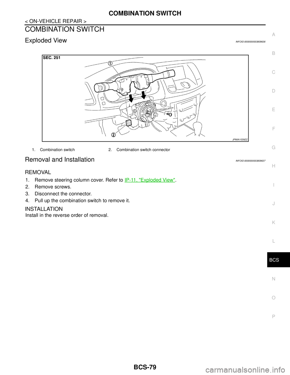
Exploded ViewINFOID:0000000003809636
Removal and InstallationINFOID:0000000003809637
REMOVAL
1. Remove steering column cover. Refer to IP-11, "Exploded View".
2. Remove screws.
3. Disconnect the connector.
4. Pull up the combination switch to remove it.
INSTALLATION
Install in the reverse order of removal.
1. Combination switch 2. Combination switch connector
JPMIA1039ZZ
Page 897 of 5121

BR-1
BRAKES
C
DE
G H
I
J
K L
M
SECTION BR
A
B
BR
N
O P
CONTENTS
BRAKE SYSTEM
SYMPTOM DIAGNOSIS ..... ..........................3
NOISE, VIBRATION AND HARSHNESS
(NVH) TROUBLESHOOTING ........................ .....
3
NVH Troubleshooting Chart ................................ ......3
PRECAUTION ...............................................4
PRECAUTIONS .............................................. .....4
Precaution for Supplemental Restraint System
(SRS) "AIR BAG" and "SEAT BELT PRE-TEN-
SIONER" ............................................................. ......
4
Precaution Necessary for Steering Wheel Rota-
tion after Battery Disconnect .....................................
4
Precaution for Procedure without Cowl Top Cover ......5
Precaution for Brake System ....................................5
ON-VEHICLE MAINTENANCE .....................6
BRAKE PEDAL .............................................. .....6
Inspection and Adjustment .................................. ......6
BRAKE FLUID .....................................................9
Inspection ............................................................ ......9
Draining .....................................................................9
Refilling .....................................................................9
Bleeding Brake System ...........................................10
BRAKE MASTER CYLINDER ........................ ....11
Inspection ............................................................ ....11
BRAKE BOOSTER ............................................12
Inspection ............................................................ ....12
FRONT DISC BRAKE .................................... ....13
BRAKE PAD .......................................................... ....13
BRAKE PAD : Inspection and Adjustment ..............13
DISC ROTOR ......................................................... ....13
DISC ROTOR : Inspection and Adjustment ............13
REAR DISC BRAKE ...................................... ....15
BRAKE PAD .......................................................... ....15
BRAKE PAD : Inspection and Adjustment ...............15
DISC ROTOR ......................................................... ....15
DISC ROTOR : Inspection and Adjustment .............15
ON-VEHICLE REPAIR .................................17
BRAKE PEDAL ................................ .................17
Exploded View ..................................................... ....17
Removal and Installation .........................................17
Inspection and Adjustment ......................................18
BRAKE PIPING ................................ .................19
FRONT ................................................................... ....19
FRONT : Exploded View .........................................19
FRONT : Hydraulic Piping .......................................20
FRONT : Removal and Installation ..........................21
FRONT : Inspection .................................................21
REAR ..................................................................... ....22
REAR : Exploded View ............................................22
REAR : Hydraulic Piping ..........................................22
REAR : Removal and Installation ............................23
REAR : Inspection ...................................................23
BRAKE MASTER CYLINDER ..........................25
Exploded View .........................................................25
Removal and Installation .........................................25
Disassembly and Assembly .....................................26
Inspection ................................................................27
BRAKE BOOSTER ...........................................28
Exploded View ..................................................... ....28
Removal and installation .........................................28
Inspection and Adjustment ......................................29
VACUUM LINES ...............................................31
Exploded View .........................................................31
Removal and Installation .........................................31
Inspection ................................................................31
Page 898 of 5121

BR-2
FRONT DISC BRAKE ........................................33
BRAKE PAD .............................................................33
BRAKE PAD : Exploded View ................................33
BRAKE PAD : Removal and Installation .................33
BRAKE PAD : Inspection ........................................34
BRAKE CALIPER ASSEMBLY ................................34
BRAKE CALIPER ASSEMBLY : Exploded View ....34
BRAKE CALIPER ASSEMBLY : Removal and In-
stallation .................................................................
35
BRAKE CALIPER ASSEMBLY : Disassembly and
Assembly ................................................................
36
BRAKE CALIPER ASSEMBLY : Inspection ...........38
REAR DISC BRAKE ..........................................39
BRAKE PAD .............................................................39
BRAKE PAD : Exploded View ................................39
BRAKE PAD : Removal and Installation .................39
BRAKE PAD : Inspection ........................................40
BRAKE CALIPER ASSEMBLY ................................40
BRAKE CALIPER ASSEMBLY : Exploded View ....40
BRAKE CALIPER ASSEMBLY : Removal and In-
stallation ..................................................................
41
BRAKE CALIPER ASSEMBLY : Disassembly and
Assembly ................................................................
42
BRAKE CALIPER ASSEMBLY : Inspection ............44
SERVICE DATA AND SPECIFICATIONS
(SDS) ..........................................................
45
SERVICE DATA AND SPECIFICATIONS
(SDS) .................................................................
45
General Specifications ............................................45
Brake Pedal ............................................................45
Brake Booster .........................................................45
Front Disc Brake .....................................................45
Rear Disc Brake ......................................................45
Page 899 of 5121
NOISE, VIBRATION AND HARSHNESS (NVH) TROUBLESHOOTING
BR-3
< SYMPTOM DIAGNOSIS >
C
D
E
G
H
I
J
K
L
MA
B
BR
N
O
P
SYMPTOM DIAGNOSIS
NOISE, VIBRATION AND HARSHNESS (NVH) TROUBLESHOOTING
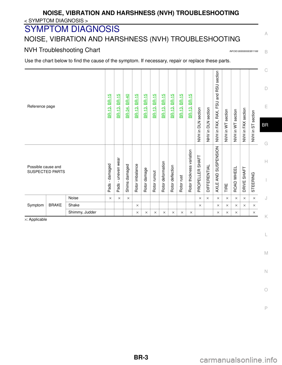
NVH Troubleshooting ChartINFOID:0000000003811166
Use the chart below to find the cause of the symptom. If necessary, repair or replace these parts.
×: ApplicableReference page
BR-13
, BR-15
BR-13
, BR-15
BR-34
, BR-40
BR-13
, BR-15
BR-13
, BR-15
BR-13
, BR-15
BR-13
, BR-15
BR-13
, BR-15
BR-13
, BR-15
BR-13
, BR-15
NVH in DLN section
NHV in DLN section
NVH in FAX, RAX, FSU and RSU section
NVH in WT section
NVH in WT section
NVH in FAX section
NVH in ST section
Possible cause and
SUSPECTED PARTS
Pads - damaged
Pads - uneven wear
Shims damaged
Rotor imbalance
Rotor damage
Rotor runout
Rotor deformation
Rotor deflection
Rotor rust
Rotor thickness variation
PROPELLER SHAFT
DIFFERENTIAL
AXLE AND SUSPENSION
TIRE
ROAD WHEEL
DRIVE SHAFT
STEERING
Symptom BRAKENoise××× ×× ×××
××
Shake×××××
××
Shimmy, Judder××××××× ××× ×
Page 900 of 5121
BR-4
< PRECAUTION >
PRECAUTIONS
PRECAUTION
PRECAUTIONS
Precaution for Supplemental Restraint System (SRS) "AIR BAG" and "SEAT BELT
PRE-TENSIONER"
INFOID:0000000003890160
The Supplemental Restraint System such as “AIR BAG” and “SEAT BELT PRE-TENSIONER”, used along
with a front seat belt, helps to reduce the risk or severity of injury to the driver and front passenger for certain
types of collision. Information necessary to service the system safely is included in the “SRS AIRBAG” and
“SEAT BELT” of this Service Manual.
WARNING:
• To avoid rendering the SRS inoperative, which could increase the risk of personal injury or death in
the event of a collision which would result in air bag inflation, all maintenance must be performed by
an authorized NISSAN/INFINITI dealer.
Improper maintenance, including incorrect removal and installation of the SRS, can lead to personal
injury caused by unintentional activation of the system. For removal of Spiral Cable and Air Bag
Module, see the “SRS AIRBAG”.
Never use electrical test equipment on any circuit related to the SRS unless instructed to in this Ser-
vice Manual. SRS wiring harnesses can be identified by yellow and/or orange harnesses or harness
connectors.
Precaution Necessary for Steering Wheel Rotation after Battery Disconnect
INFOID:0000000003890161
NOTE:
Before removing and installing any control units, first turn the push-button ignition switch to the LOCK posi-
tion, then disconnect both battery cables.
After finishing work, confirm that all control unit connectors are connected properly, then re-connect both
battery cables.
Always use CONSULT-III to perform self-diagnosis as a part of each function inspection after finishing work.
If a DTC is detected, perform trouble diagnosis according to self-diagnosis results.
This vehicle is equipped with a push-button ignition switch and a steering lock unit.
If the battery is disconnected or discharged, the steering wheel will lock and cannot be turned.
If turning the steering wheel is required with the battery disconnected or discharged, follow the procedure
below before starting the repair operation.
OPERATION PROCEDURE
1. Connect both battery cables.
NOTE:
Supply power using jumper cables if battery is discharged.
2. Turn the push-button ignition switch to ACC position.
(At this time, the steering lock will be released.)
3. Disconnect both battery cables. The steering lock will remain released with both battery cables discon-
nected and the steering wheel can be turned.
4. Perform the necessary repair operation.
5. When the repair work is completed, re-connect both battery cables. With the brake pedal released, turn
the push-button ignition switch from ACC position to ON position, then to LOCK position. (The steering
wheel will lock when the push-button ignition switch is turned to LOCK position.)
6. Perform self-diagnosis check of all control units using CONSULT-III.