NISSAN TEANA 2014 Service Manual
Manufacturer: NISSAN, Model Year: 2014, Model line: TEANA, Model: NISSAN TEANA 2014Pages: 4801, PDF Size: 51.2 MB
Page 2631 of 4801
OIL
HA-25
< PERIODIC MAINTENANCE >
C
D E
F
G H
J
K L
M A
B
HA
N
O P
OIL
DescriptionINFOID:0000000009463930
MAINTENANCE OF OIL LEVEL
The compressor oil is circulating in the system together wi th the refrigerant. It is necessary to fill compressor
with oil when replacing A/C system parts or when a large amount of refrigerant leakage is detected. It is impor-
tant to always maintain oil level within the spec ified level, otherwise the following conditions may occur:
• Insufficient oil amount: Stuck compressor
• Excessive oil amount: Insufficient coo ling (caused by insufficient heat exchange)
InspectionINFOID:0000000009463931
If a compressor is malfunctioning (internal noise, insufficient cooling), check the compressor oil.
1.COMPRESSOR OIL JUDGMENT
1. Remove the compressor. Refer to HA-30, "COMPRESSOR : Removal and Installation"
.
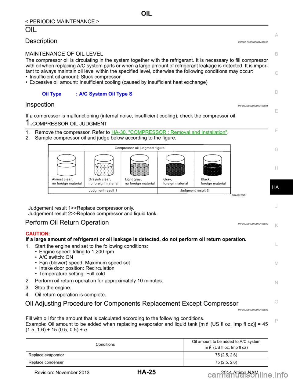
2. Sample compressor oil and judge below according to the figure.
Judgement result 1>>Replace compressor only.
Judgement result 2>>Replace compressor and liquid tank.
Perform Oil Return OperationINFOID:0000000009463932
CAUTION:
If a large amount of refrigerant or oil leakage is detected, do not perform oil return operation.
1. Start the engine and set to the following conditions: • Engine speed: Idling to 1,200 rpm
• A/C switch: ON
• Fan (blower) speed: Maximum speed set
• Intake door position: Recirculation
• Temperature setting: Full cold
2. Perform oil return operation for approximately 10 minutes.
3. Stop the engine.
4. Oil return operation is complete.
Oil Adjusting Procedure for Component s Replacement Except Compressor
INFOID:0000000009463933
Fill with oil for the amount that is calculated according to the following conditions.
Example: Oil amount to be added when replacing evaporator and liquid tank [m (US fl oz, Imp fl oz)] = 45
(1.5, 1.6) + 15 (0.5, 0.5) + α
Oil Type : A/C System Oil Type S
JSIIA0927GB
Conditions
Oil amount to be added to A/C system
m (US fl oz, Imp fl oz)
Replace evaporator 75 (2.5, 2.6)
Replace condenser 75 (2.5, 2.6)
Revision: November 20132014 Altima NAM
Page 2632 of 4801
HA-26
< PERIODIC MAINTENANCE >
OIL
Oil Adjusting Procedure fo r Compressor Replacement
INFOID:0000000009463934
1. Before connecting recovery/recycling equipment to vehicle, check recovery/recycling equipment gauges.
No refrigerant pressure should be displayed. If NG, recover refrigerant from equipment lines.
2. Connect recovery/recycling equipment to vehicle. Confi rm refrigerant purity in supply tank using recovery/
recycling equipment and refrigerant identifier. If NG, refer to HA-3, "Precaution for Working with HFC-134a
(R-134a)".
3. Confirm refrigerant purity in vehi cle A/C system using recovery/recycling equipment and refrigerant identi-
fier. If NG, refer to HA-3, "Precaution for Working with HFC-134a (R-134a)"
.
4. Discharge refrigerant into the refrigerant recove ry/recycling equipment. Measure oil discharged into the
recovery/recycling equipment.
Replace liquid tank 5 (0.2, 0.2)
Refrigerant leakage is detected Large amount leakage 30 (1.0, 1.1)
Small amount leakage —
Oil amount that is recycled together with refrigerant during recycle operation α
Conditions
Oil amount to be added to A/C system
m (US fl oz, Imp fl oz)
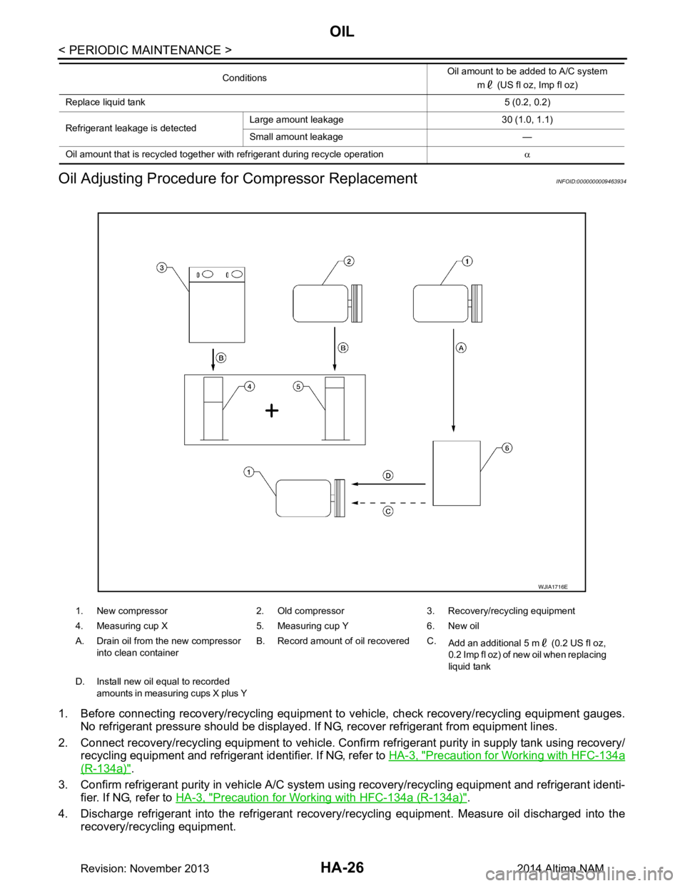
1. New compressor 2. Old compressor 3. Recovery/recycling equipment
4. Measuring cup X 5. Measuring cup Y 6. New oil
A. Drain oil from the new compressor into clean container B. Record amount of oil recovered C.
Add an additional 5 m (0.2 US fl oz,
0.2 Imp fl oz) of new oil when replacing
liquid tank
D. Install new oil equal to recorded amounts in measuring cups X plus Y
WJIA1716E
Revision: November 20132014 Altima NAM
Page 2633 of 4801

OIL
HA-27
< PERIODIC MAINTENANCE >
C
D E
F
G H
J
K L
M A
B
HA
N
O P
5. Drain the oil from the “old” (removed) compress or into a graduated container and recover the amount of
oil drained.
6. Drain the oil from the “new” compressor into a separate, clean container.
7. Measure an amount of new oil installed equal to am ount drained from “old” compressor. Add this oil to
“new” compressor through the suction port opening.
8. Measure an amount of new oil equal to the amount recovered during discharging. Add this oil to “new” compressor through the suction port opening.
9. If the liquid tank also needs to be replaced, add an additional 5 m (0.2 US fl oz, 0.2 Imp fl oz) of oil at this
time.
CAUTION:
Do not add the 5 m (0.2 US fl oz, 0.2 Imp fl oz) of oil if only replacing the compressor and not the
liquid tank.
Revision: November 20132014 Altima NAM
Page 2634 of 4801

HA-28
< PERIODIC MAINTENANCE >
PERFORMANCE TEST
PERFORMANCE TEST
InspectionINFOID:0000000009463935
INSPECTION PROCEDURE
1. Connect recovery/recycling/recharging equipment (for HFC-134a) or manifold gauge.
2. Start the engine, and set to the following condition.
Test condition
3. Maintain test condition until A/C system becomes stable. (Approximately 10 minutes)
4. Check that test results of “recirculating-to-disc harge air temperature” and “ambient air temperature-to-
operating pressure” are within the specified value.
5. When test results are within the spec ified value, inspection is complete.
If any of test result is out of the specifi ed value, perform diagnosis by gauge pressure. Refer to HA-17,
"Symptom Table".
RECIRCULATING-TO-DISCHARGE AIR TEMPERATURE TABLE
AMBIENT AIR TEMPERATURE-TO-OPERATING PRESSURE TABLE
Surrounding condition Indoors or in the shade (in a well-ventilated place)
Vehicle condition Door Closed
Door glass Full open
Hood Open
Engine speed Idle speed
A/C condition Temperature control switch or dial Full cold
A/C switch ON
Air outlet VENT (ventilation)
Intake door position Recirculation
Fan (blower) speed Maximum speed set
Inside air (Recirculating air) at blower assembly inlet Discharge air temperature from center ventilator
°C ( °F)
Relative humidity
% Air temperature
°C ( °F)
50 – 60 20 (68) 4.7 – 6.7 (40 – 44)
25 (77) 8.6 – 11.1 (47 – 52)
30 (86) 12.6 – 15.6 (55 – 60)
35 (95) 19.0 – 22.5 (66 – 73)
60 – 70 20 (68) 6.7 – 8.7 (44 – 48)
25 (77) 11.1 – 13.6 (52 – 56)
30 (86) 15.6 – 18.6 (60 – 65)
35 (95) 22.5 – 26.0 (73 – 79)
Revision: November 20132014 Altima NAM
Page 2635 of 4801

PERFORMANCE TESTHA-29
< PERIODIC MAINTENANCE >
C
D E
F
G H
J
K L
M A
B
HA
N
O P
Fresh air High-pressure (Discharge side)
kPa (kg/cm
2, psi) Low-pressure (Suction side)
kPa (kg/cm2, psi)
Relative humidity
% Air temperature
°C ( °F)
50 – 70 25 (77)
909 – 1,112
(9.2 – 11.3, 131.8 – 161.2) 159 – 194
(1.6 – 2.0, 23.1 – 28.1)
30 (86) 1,073 -– 1,312
(10.9 – 13.4, 155.6 – 190.2) 211 – 259
(2.2 – 2.6, 30.6 – 37.6)
35 (95) 1,445 – 1,766
(14.7 – 18.0, 209.5 – 256.1) 247 – 300
(2.5 – 3.1, 35.8 – 43.5)
40 (104) 1,650 – 2,017
(16.8 – 20.6, 239.3 – 292.5) 290 – 355
(3.0 – 3.6, 42.1 – 51.5)
Revision: November 20132014 Altima NAM
Page 2636 of 4801
HA-30
< REMOVAL AND INSTALLATION >
COMPRESSOR
REMOVAL AND INSTALLATION
COMPRESSOR
COMPRESSOR
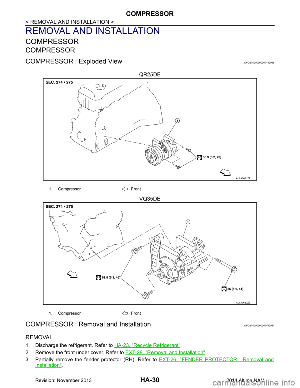
COMPRESSOR : Exploded ViewINFOID:0000000009463936
QR25DEVQ35DE
COMPRESSOR : Removal and InstallationINFOID:0000000009463937
REMOVAL
1. Discharge the refrigerant. Refer to HA-23, "Recycle Refrigerant".
2. Remove the front under cover. Refer to EXT-28, "Removal and Installation"
.
3. Partially remove the fender protector (RH). Refer to EXT-26, "FENDER PROTECTOR : Removal and
Installation".
ALIIA0631ZZ
1. Compressor Front
ALIIA0632ZZ
1. Compressor Front
Revision: November 20132014 Altima NAM
Page 2637 of 4801
COMPRESSORHA-31
< REMOVAL AND INSTALLATION >
C
D E
F
G H
J
K L
M A
B
HA
N
O P
4. Remove the drive belt. Refer to EM-19, "Removal and Installation" (QR25DE), or EM-134, "Removal and
Installation" (VQ35DE).
5. Reposition the power steering line. Refer to ST-40, "Exploded View"
.
6. Disconnect the A/C pipes from the compressor. CAUTION:
Cap or wrap the joint of the A/C pipes with suitable material such as vinyl tape to avoid the entry of
air.
7. Disconnect the harness connector from the compressor.
8. Remove the compressor bolts and the compressor.
INSTALLATION
Installation is in the reverse order of removal.
CAUTION:
• Do not reuse the O-rings.
• Apply A/C compressor oil to th e new O-rings for installation.
• After charging the A/C refriger ant, check for leaks. Refer to HA-21, "Leak Test"
.
• Tighten the compressor bolts to specification. Refer to HA-30, "COMPRESSOR : Exploded View"
.
MAGNET CLUTCH
MAGNET CLUTCH : Removal and InstallationINFOID:0000000009463938
REMOVAL
1. Remove the front under cover. Refer to EXT-28, "Removal and Installation".
2. Partially remove the fender protector (RH). Refer to EXT-26, "FENDER PROTECTOR : Removal and
Installation".
3. Remove the drive belt. Refer to EM-19, "Removal and Installation"
(QR25DE), or EM-134, "Removal and
Installation" (VQ35DE).
4. Remove the center bolt by holding the clutch disc steady using a suitable tool.
5. Remove the clutch disc and shims. CAUTION:
Retain all the shim s for installation.
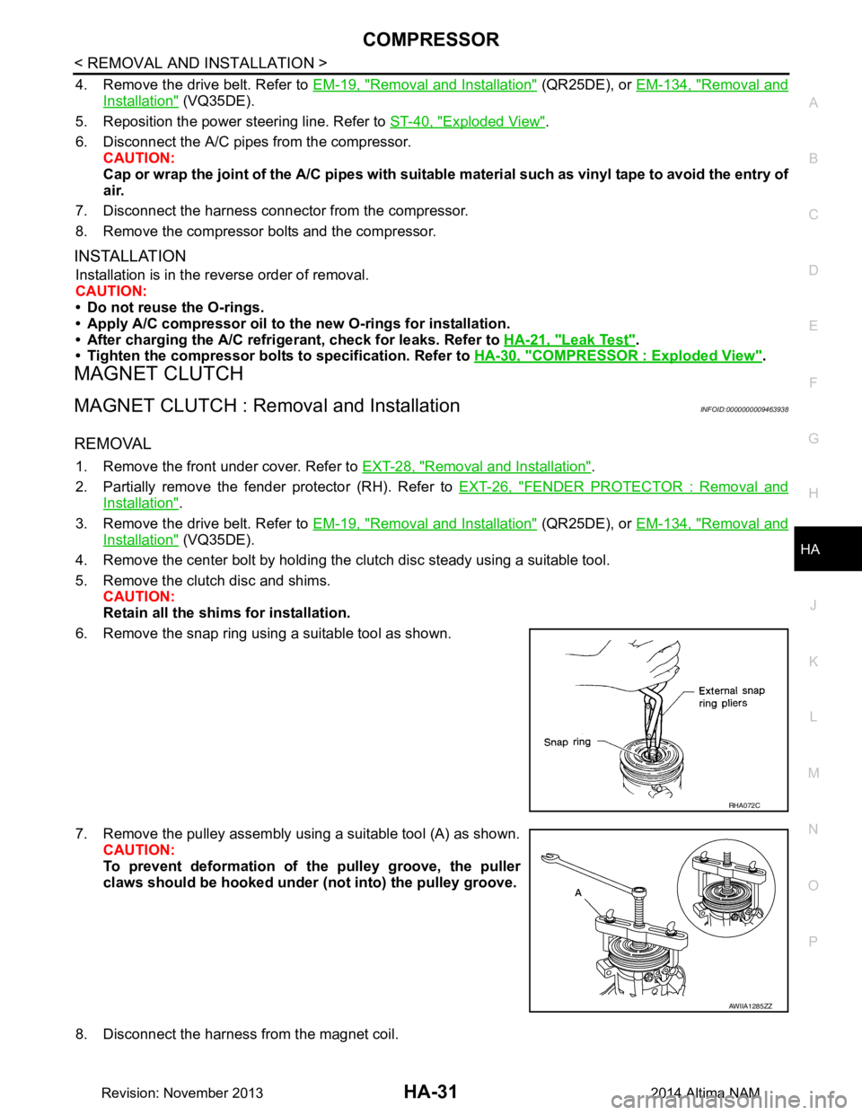
6. Remove the snap ring using a suitable tool as shown.
7. Remove the pulley assembly using a suitable tool (A) as shown. CAUTION:
To prevent deformation of th e pulley groove, the puller
claws should be hooked under (not into) the pulley groove.
8. Disconnect the harness from the magnet coil.
RHA072C
AWIIA1285ZZ
Revision: November 20132014 Altima NAM
Page 2638 of 4801
HA-32
< REMOVAL AND INSTALLATION >
COMPRESSOR
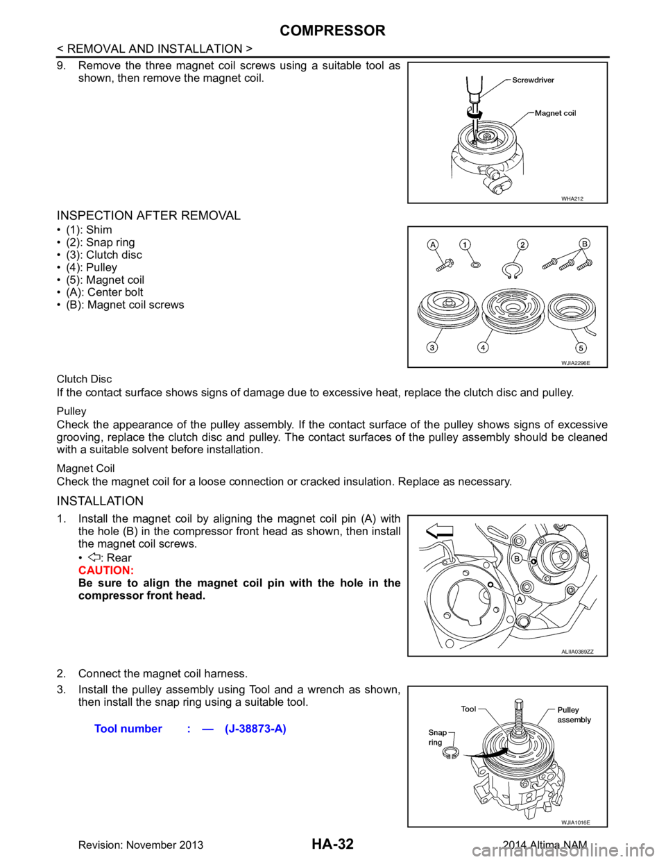
9. Remove the three magnet coil screws using a suitable tool asshown, then remove the magnet coil.
INSPECTION AFTER REMOVAL
•(1): Shim
• (2): Snap ring
• (3): Clutch disc
• (4): Pulley
• (5): Magnet coil
• (A): Center bolt
• (B): Magnet coil screws
Clutch Disc
If the contact surface shows signs of damage due to excessive heat, replace the clutch disc and pulley.
Pulley
Check the appearance of the pulley assembly. If the cont act surface of the pulley shows signs of excessive
grooving, replace the clutch disc and pulley. The contact surfaces of the pulley assembly should be cleaned
with a suitable solvent before installation.
Magnet Coil
Check the magnet coil for a loose connection or cracked insulation. Replace as necessary.
INSTALLATION
1. Install the magnet coil by aligning the magnet coil pin (A) with
the hole (B) in the compressor front head as shown, then install
the magnet coil screws.
• : Rear
CAUTION:
Be sure to align the magnet coil pin with the hole in the
compressor front head.
2. Connect the magnet coil harness.
3. Install the pulley assembly using Tool and a wrench as shown, then install the snap ring using a suitable tool.
WHA212
WJIA2296E
ALIIA0389ZZ
Tool number : — (J-38873-A)
WJIA1016E
Revision: November 20132014 Altima NAM
Page 2639 of 4801
COMPRESSORHA-33
< REMOVAL AND INSTALLATION >
C
D E
F
G H
J
K L
M A
B
HA
N
O P
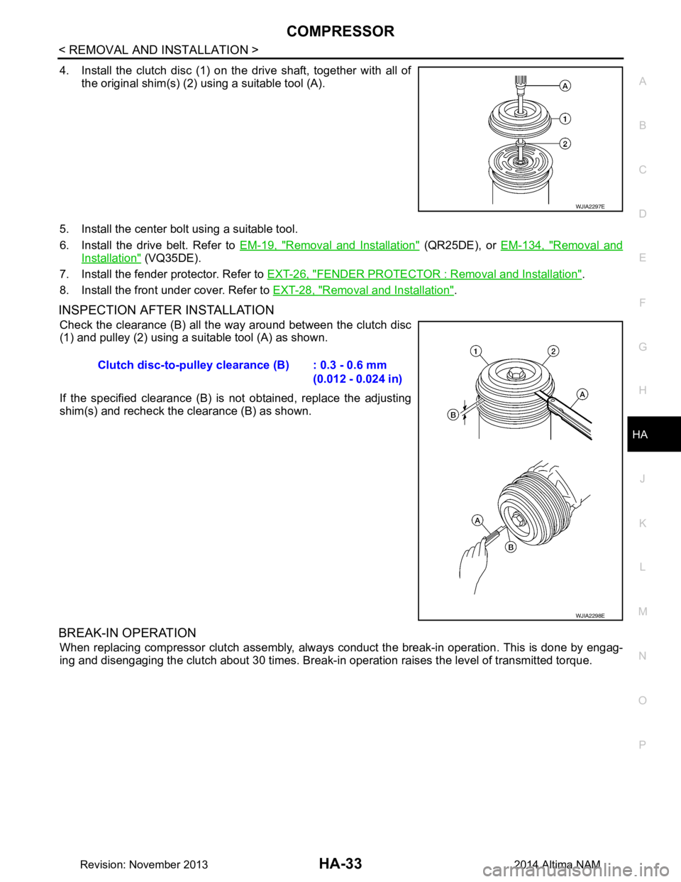
4. Install the clutch disc (1) on the drive shaft, together with all of the original shim(s) (2) using a suitable tool (A).
5. Install the center bolt using a suitable tool.
6. Install the drive belt. Refer to EM-19, "Removal and Installation"
(QR25DE), or EM-134, "Removal and
Installation" (VQ35DE).
7. Install the fender protector. Refer to EXT-26, "FENDER PROTECTOR : Removal and Installation"
.
8. Install the front under cover. Refer to EXT-28, "Removal and Installation"
.
INSPECTION AFTER INSTALLATION
Check the clearance (B) all the way around between the clutch disc
(1) and pulley (2) using a suitable tool (A) as shown.
If the specified clearance (B) is not obtained, replace the adjusting
shim(s) and recheck the clearance (B) as shown.
BREAK-IN OPERATION
When replacing compressor clutch assembly, always conduct the break-in operation. This is done by engag-
ing and disengaging the clutch about 30 times. Break-in operation raises the level of transmitted torque.
WJIA2297E
Clutch disc-to-pulley clearance (B) : 0.3 - 0.6 mm
(0.012 - 0.024 in)
WJIA2298E
Revision: November 20132014 Altima NAM
Page 2640 of 4801
HA-34
< REMOVAL AND INSTALLATION >
COOLER PIPE AND HOSE
COOLER PIPE AND HOSE
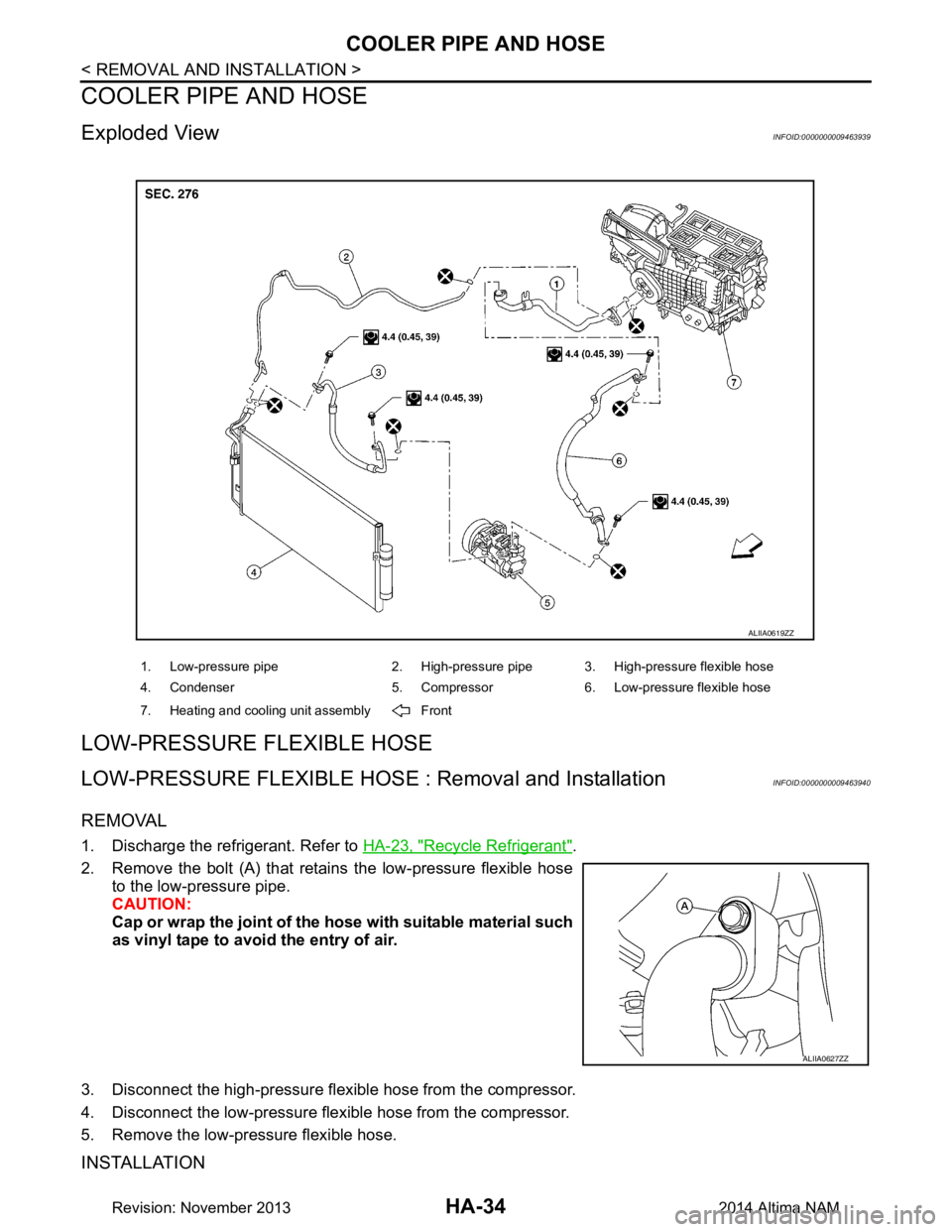
Exploded ViewINFOID:0000000009463939
LOW-PRESSURE FLEXIBLE HOSE
LOW-PRESSURE FLEXIBLE HOSE : Removal and InstallationINFOID:0000000009463940
REMOVAL
1. Discharge the refrigerant. Refer to HA-23, "Recycle Refrigerant".
2. Remove the bolt (A) that retain s the low-pressure flexible hose
to the low-pressure pipe.
CAUTION:
Cap or wrap the joint of the ho se with suitable material such
as vinyl tape to avoid the entry of air.
3. Disconnect the high-pressure flexible hose from the compressor.
4. Disconnect the low-pressure flexible hose from the compressor.
5. Remove the low-pressure flexible hose.
INSTALLATION
1. Low-pressure pipe 2. High-pressure pipe 3. High-pressure flexible hose
4. Condenser 5. Compressor 6. Low-pressure flexible hose
7. Heating and cooling unit assembly Front
ALIIA0619ZZ
ALIIA0627ZZ
Revision: November 20132014 Altima NAM