NISSAN TEANA 2014 Service Manual
Manufacturer: NISSAN, Model Year: 2014, Model line: TEANA, Model: NISSAN TEANA 2014Pages: 4801, PDF Size: 51.2 MB
Page 281 of 4801
PRECAUTIONSBRM-3
< PRECAUTION >
C
D E
F
G H
I
J
L
M A
B
BRM
N
O P
PRECAUTION
PRECAUTIONS
Precaution for Supplemental Restraint System (SRS) "AIR BAG" and "SEAT BELT
PRE-TENSIONER"
INFOID:0000000009951573
The Supplemental Restraint System such as “A IR BAG” and “SEAT BELT PRE-TENSIONER”, used along
with a front seat belt, helps to reduce the risk or severi ty of injury to the driver and front passenger for certain
types of collision. Information necessary to service t he system safely is included in the SR and SB section of
this Service Manual.
WARNING:
• To avoid rendering the SRS inoper ative, which could increase the risk of personal injury or death in
the event of a collision which would result in air bag inflation, all maintenance must be performed by
an authorized NISSAN/INFINITI dealer.
• Improper maintenance, including in correct removal and installation of the SRS, can lead to personal
injury caused by unintentional act ivation of the system. For removal of Spiral Cable and Air Bag
Module, see the SR section.
• Do not use electrical test equipm ent on any circuit related to the SRS unless instructed to in this
Service Manual. SRS wiring harnesses can be identi fied by yellow and/or orange harnesses or har-
ness connectors.
PRECAUTIONS WHEN USING POWER TOOLS (AIR OR ELECTRIC) AND HAMMERS
WARNING:
• When working near the Airbag Diagnosis Sensor Un it or other Airbag System sensors with the Igni-
tion ON or engine running, DO NOT use air or el ectric power tools or strike near the sensor(s) with a
hammer. Heavy vibration could activate the sensor( s) and deploy the air bag(s), possibly causing
serious injury.
• When using air or electric power tools or hammers , always switch the Ignition OFF, disconnect the
battery and wait at least three mi nutes before performing any service.
Revision: November 20132014 Altima NAM
Page 282 of 4801

BRM-4
< PRECAUTION >
HANDLING PRECAUTIONS FOR PLASTICS
HANDLING PRECAUTIONS FOR PLASTICS
Precautions For PlasticsINFOID:0000000009464963
1. When repairing and painting a portion of the body adjacent to plastic parts, consider their characteristics
(influence of heat and solvent) and remove them if neces sary or take suitable measures to protect them.
2. Plastic parts should be repaired and painted using methods suiting the materials
, characteristics.
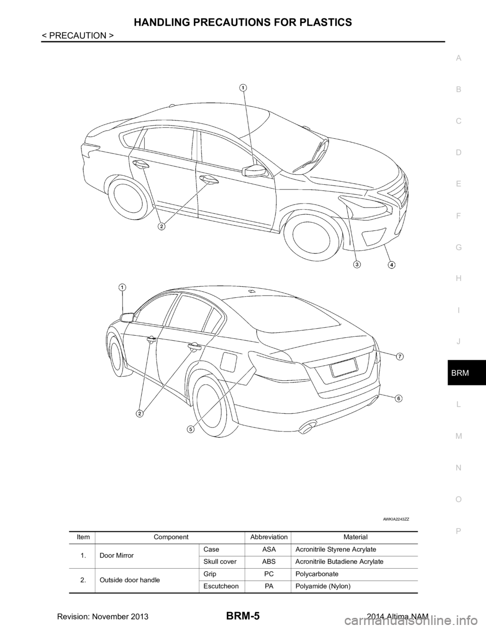
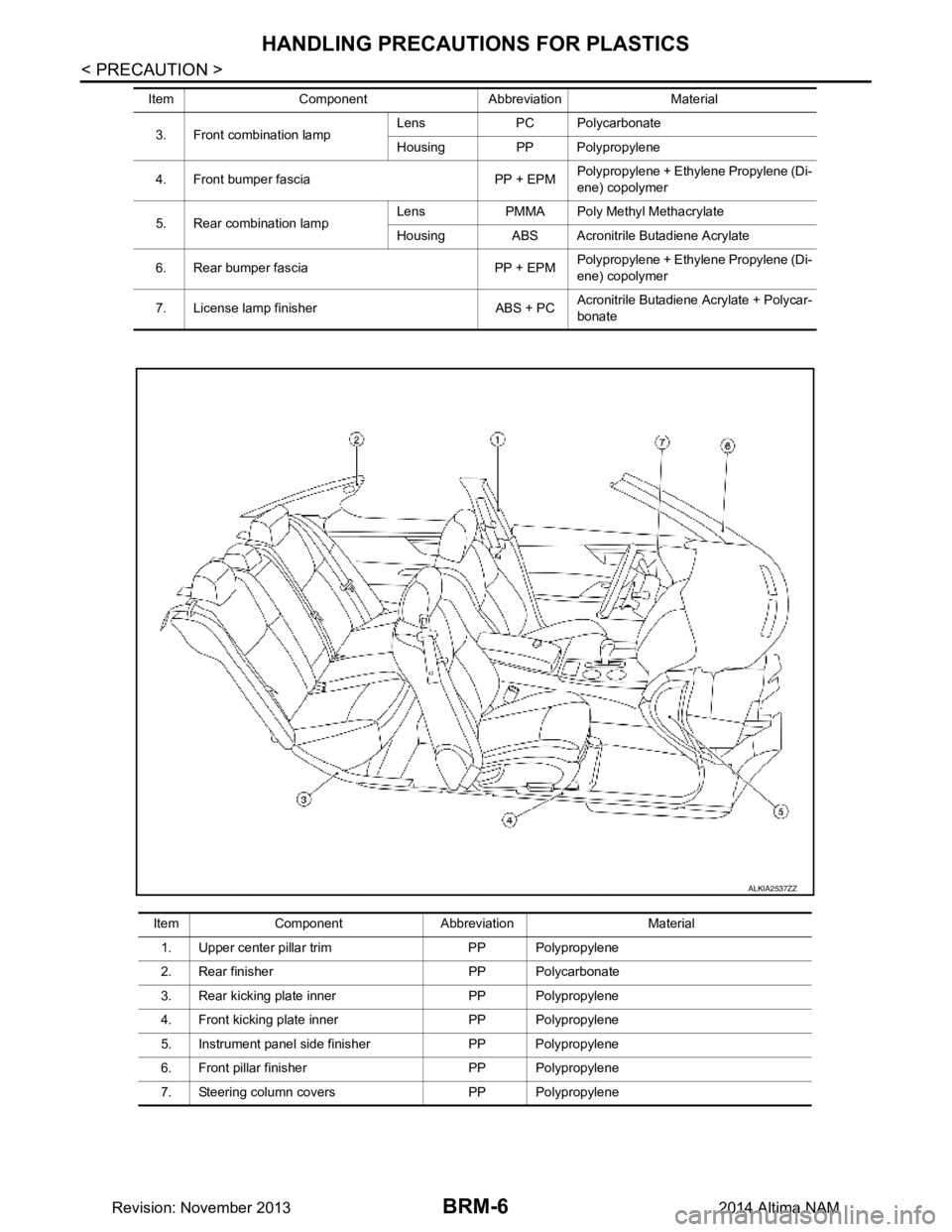
LOCATION OF PLASTIC PARTS
Abbre- viation Material name Heat resisting
temperature °C( °F) Resistance to gasoline and
solvents Other cautions
PE Polyethylene 60(140) Gasoline and most solvents are
harmless if applied for a very
short time (wipe up quickly). Flammable
PVC Poly Vinyl Chloride 80(176) Same as above. Poison gas is emitted
when burned.
EPM/
EPDM Ethylene Propylene (Diene) co-
polymer 80(176) Same as above. Flammable
PP Polypropylene 90(194) Same as above. Flammable, avoid bat-
tery acid.
UP Unsaturated Polyester 90(194) Same as above. Flammable
PS Polystyrene 80(176) Avoid solvents. Flammable
ABS Acrylonitrile Butadiene Styrene 80(176) Avoid gasoline and solvents.
PMMA Poly Methyl Methacrylate 85(185) Same as above.
EVAC Ethylene Vinyl Acetate 90(194) Same as above.
ASA Acrylonitrile Styrene Acrylate 100(222) Same as above. Flammable
PPE Poly Phenylene Ether 110(230) Same as above.
PC Polycarbonate 120(248) Same as above.
PAR Polyarylate 180(356) Same as above.
PUR Polyurethane 90(194) Same as above.
POM Poly Oxymethylene 120(248) Same as above. Avoid battery acid.
PBT+
PC Poly Butylene Terephthalate +
Polycarbonate 120(248) Same as above. Flammable
PA Polyamide 140(284) Same as above. Avoid immersing in wa-
ter.
PBT Poly Butylene Terephthalate 140(284) Same as above.
PET Polyester 180(356) Same as above.
PEI Polyetherimide 200(392) Same as above.
Revision: November 20132014 Altima NAM
Page 283 of 4801
HANDLING PRECAUTIONS FOR PLASTICSBRM-5
< PRECAUTION >
C
D E
F
G H
I
J
L
M A
B
BRM
N
O P
Item Component Abbreviation Material 1. Door Mirror Case ASA Acronitrile Styrene Acrylate
Skull cover ABS Acronitr ile Butadiene Acrylate
2. Outside door handle Grip PC Polycarbonate
Escutcheon PA Polyamide (Nylon)
AWKIA2243ZZ
Revision: November 20132014 Altima NAM
Page 284 of 4801
BRM-6
< PRECAUTION >
HANDLING PRECAUTIONS FOR PLASTICS
3. Front combination lampLens PC Polycarbonate
Housing PP Polypropylene
4. Front bumper fascia PP + EPM Polypropylene + Ethylene Propylene (Di-
ene) copolymer
5. Rear combination lamp Lens PMMA Poly Methyl Methacrylate
Housing ABS Acronitrile Butadiene Acrylate
6. Rear bumper fascia PP + EPM Polypropylene + Ethylene Propylene (Di-
ene) copolymer
7. License lamp finisher ABS + PC Acronitrile Butadiene Acrylate + Polycar-
bonate
Item Component Abbreviation Material
Item Component Abbreviation Material
1. Upper center pillar trim PP Polypropylene
2. Rear finisher PP Polycarbonate
3. Rear kicking plate inner PP Polypropylene
4. Front kicking plate inner PP Polypropylene
5. Instrument panel side finisher PP Polypropylene
6. Front pillar finisher PP Polypropylene
7. Steering column covers PP Polypropylene
ALKIA2537ZZ
Revision: November 20132014 Altima NAM
Page 285 of 4801
PRECAUTIONS IN REPAIRING HIGH STRENGTH STEELBRM-7
< PRECAUTION >
C
D E
F
G H
I
J
L
M A
B
BRM
N
O P
PRECAUTIONS IN REPAIRIN G HIGH STRENGTH STEEL
High Strength Steel (HSS)INFOID:0000000009464964
High strength steel is used for body panel s in order to reduce vehicle weight.
Accordingly, precautions in repairing automotive bodies made of high strength steel are described below:
SP130 is the most commonly used HSS.
Read the following precautions when repairing HSS.
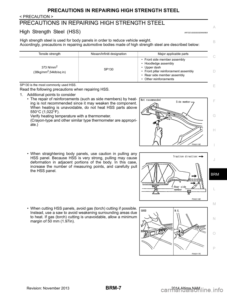
1. Additional points to consider • The repair of reinforcements (such as side members) by heat-
ing is not recommended since it may weaken the component.
When heating is unavoidable, do not heat HSS parts above
550 °C (1,022 °F).
Verify heating temperature with a thermometer.
(Crayon-type and other similar type thermometer are appropri-
ate.)
• When straightening body panels, use caution in pulling any HSS panel. Because HSS is very strong, pulling may cause
deformation in adjacent portions of the body. In this case,
increase the number of measuring points, and carefully pull
the HSS panel.
• When cutting HSS panels, avoid gas (torch) cutting if possible. Instead, use a saw to avoid weakening surrounding areas due
to heat. If gas (torch) cutting is unavoidable, allow a minimum
margin of 50 mm (1.97in).
Tensile strength Nissan/Infiniti designation Major applicable parts
373 N/mm
2
(38kg/mm2,54klb/sq in) SP130• Front side member assembly
• Hoodledge assembly
• Upper dash
• Front pillar reinforcement assembly
• Rear side member assembly
• Other reinforcements
PIIA0115E
PIIA0116E
PIIA0117E
Revision: November 20132014 Altima NAM
Page 286 of 4801
BRM-8
< PRECAUTION >
PRECAUTIONS IN REPAIRING HIGH STRENGTH STEEL
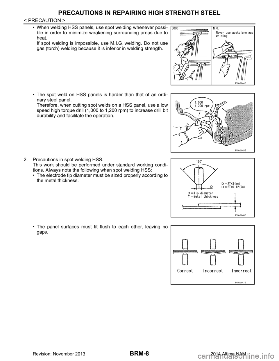
• When welding HSS panels, use spot welding whenever possi-ble in order to minimize weakening surrounding areas due to
heat.
If spot welding is impossible, use M.I.G. welding. Do not use
gas (torch) welding because it is inferior in welding strength.
• The spot weld on HSS panels is harder than that of an ordi- nary steel panel.
Therefore, when cutting spot welds on a HSS panel, use a low
speed high torque drill (1,000 to 1,200 rpm) to increase drill bit
durability and facilitate the operation.
2. Precautions in spot welding HSS. This work should be performed under standard working condi-
tions. Always note the following when spot welding HSS:
• The electrode tip diameter must be sized properly according to the metal thickness.
• The panel surfaces must fit flush to each other, leaving no gaps.
PIIA0144E
PIIA0145E
PIIA0146E
PIIA0147E
Revision: November 20132014 Altima NAM
Page 287 of 4801
PRECAUTIONS IN REPAIRING HIGH STRENGTH STEELBRM-9
< PRECAUTION >
C
D E
F
G H
I
J
L
M A
B
BRM
N
O P
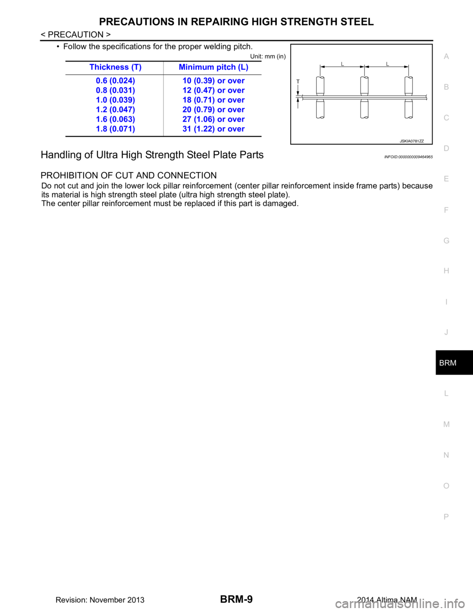
• Follow the specifications for the proper welding pitch.
Unit: mm (in)
Handling of Ultra High Str ength Steel Plate PartsINFOID:0000000009464965
PROHIBITION OF CUT AND CONNECTION
Do not cut and join the lower lock pillar reinforcement (center pillar reinforcement inside frame parts) because
its material is high strength steel pl ate (ultra high strength steel plate).
The center pillar reinforcement must be replaced if this part is damaged. Thickness (T) Minimum pitch (L)
0.6 (0.024)
0.8 (0.031)
1.0 (0.039)
1.2 (0.047)
1.6 (0.063)
1.8 (0.071) 10 (0.39) or over
12 (0.47) or over
18 (0.71) or over
20 (0.79) or over
27 (1.06) or over
31 (1.22) or over
JSKIA0781ZZ
Revision: November 20132014 Altima NAM
Page 288 of 4801
BRM-10
< PREPARATION >
REPAIRING MATERIAL
PREPARATION
REPAIRING MATERIAL
Foam RepairINFOID:0000000009464966
During factory assembly, foam insulators are installed in certain body panels and locations around the vehicle.
Use the following procedure(s) to replace any factory-installed foam insulators.
URETHANE FOAM APPLICATIONS
Use commercially available Urethane foam for sealant (foam material) repair of material used on vehicle.
Read instructions on product for fill procedures.
FILL PROCEDURES
Example of foaming agent filling operation procedure:
1. Fill procedures after installation of service part.
a. Eliminate foam material remaining on vehicle side.
b. Clean area after eliminating form insulator and foam material.
c. Install service part.
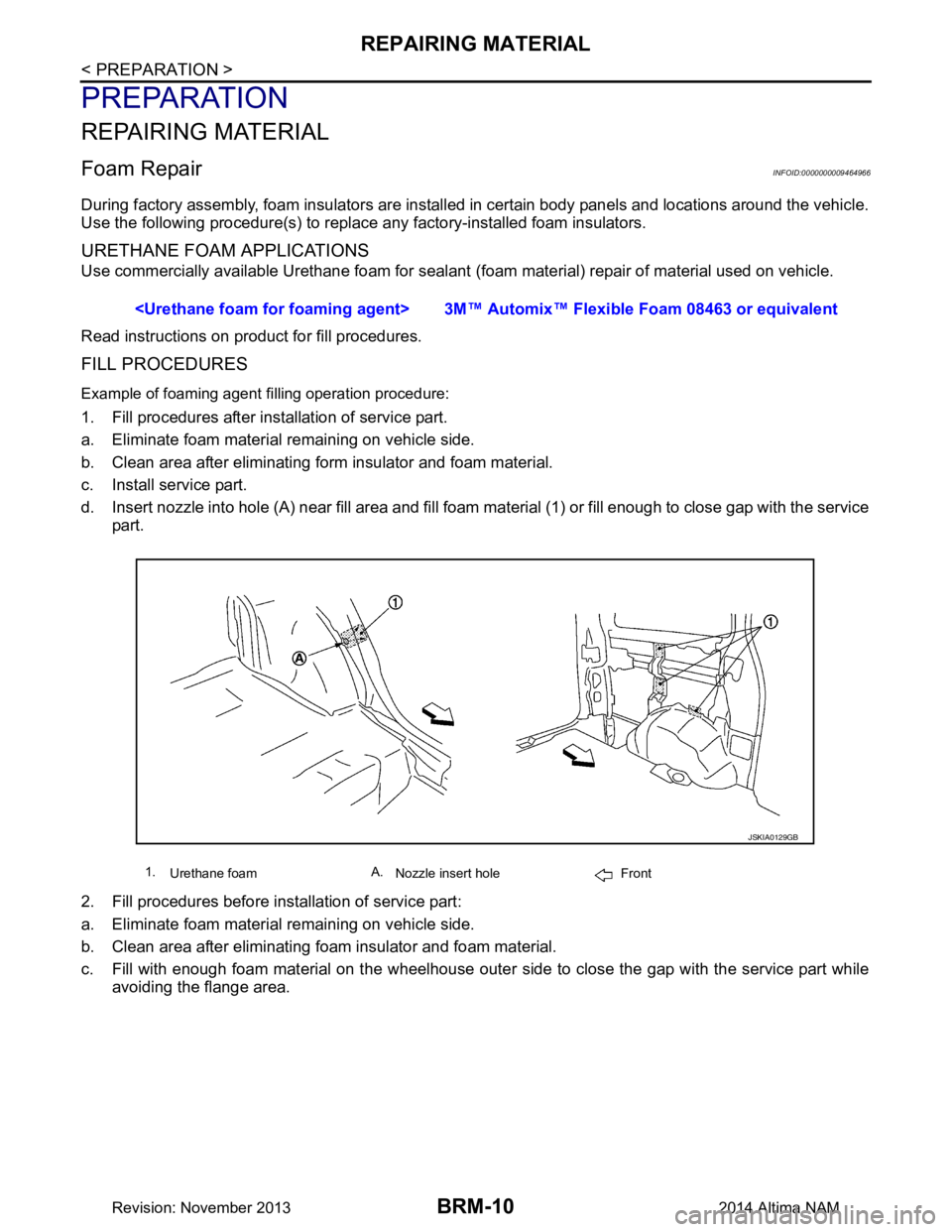
d. Insert nozzle into hole (A) near fill area and fill foam material (1) or fill enough to close gap with the service
part.
2. Fill procedures before installation of service part:
a. Eliminate foam material remaining on vehicle side.
b. Clean area after eliminating foam insulator and foam material.
c. Fill with enough foam material on the wheelhouse outer side to close the gap with the service part while
avoiding the flange area.
tomix™ Flexible Foam 08463 or equivalent
1.
Urethane foam A.
Nozzle insert hole Front
JSKIA0129GB
Revision: November 20132014 Altima NAM
Page 289 of 4801
REPAIRING MATERIALBRM-11
< PREPARATION >
C
D E
F
G H
I
J
L
M A
B
BRM
N
O P
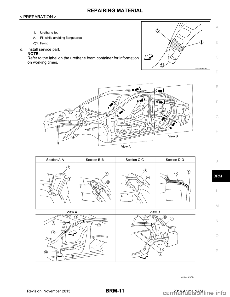
d. Install service part. NOTE:
Refer to the label on the urethane foam container for information
on working times.
1. Urethane foam
A. Fill while avoiding flange area
: Front
JSKIA0130GB
ALKIA2576GB
Revision: November 20132014 Altima NAM
Page 290 of 4801

BRM-12
< PREPARATION >
REPAIRING MATERIAL
1. Body side outer 2. Body side insulation (foam) front pillar3. Body side insulation (foam) roof
side rail
4. Roof panel assembly 5. Body side insulation (foam) rear pillar6. Body side insulation (foam) rear
pillar lower
7. Body side insulation strip, front pillar lower re inforcement Front
Revision: November 20132014 Altima NAM