NISSAN TEANA 2014 Service Manual
Manufacturer: NISSAN, Model Year: 2014, Model line: TEANA, Model: NISSAN TEANA 2014Pages: 4801, PDF Size: 51.2 MB
Page 3261 of 4801
MWI-6
< SYSTEM DESCRIPTION >
COMPONENT PARTS
SYSTEM DESCRIPTION
COMPONENT PARTS
METER SYSTEM
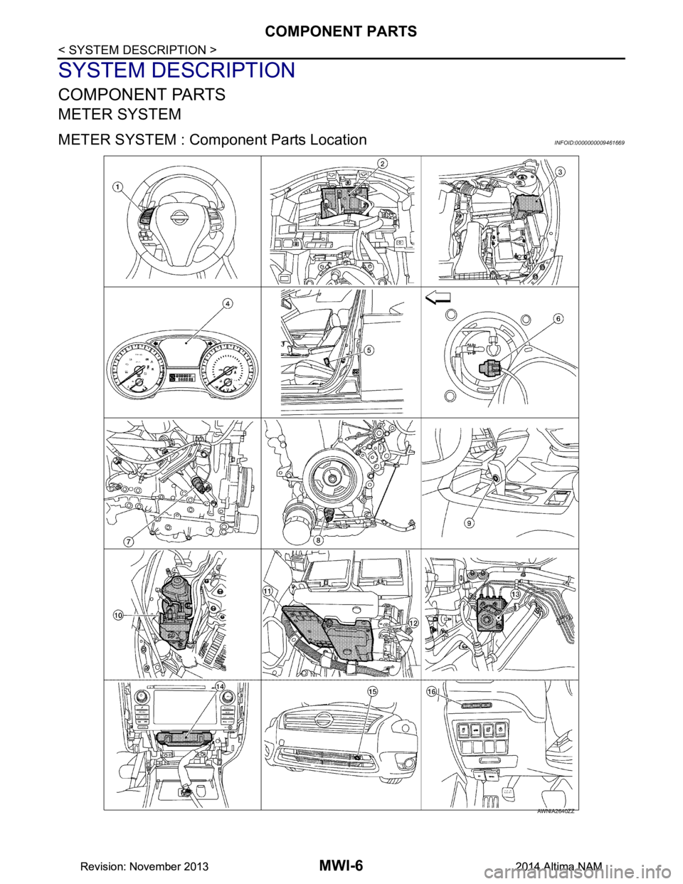
METER SYSTEM : Component Parts LocationINFOID:0000000009461669
AWNIA2640ZZ
Revision: November 20132014 Altima NAMRevision: November 20132014 Altima NAM
Page 3262 of 4801
MWI
COMPONENT PARTSMWI-7
< SYSTEM DESCRIPTION >
C
D E
F
G H
I
J
K L
M B
A
O P
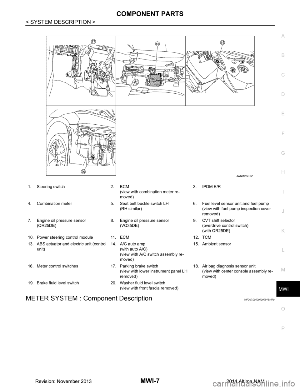
METER SYSTEM : Component DescriptionINFOID:0000000009461670
1. Steering switch 2. BCM (view with combination meter re-
moved) 3. IPDM E/R
4. Combination meter 5. Seat belt buckle switch LH (RH similar) 6. Fuel level sensor unit and fuel pump
(view with fuel pump inspection cover
removed)
7. Engine oil pressure sensor (QR25DE) 8. Engine oil pressure sensor
(VQ35DE) 9. CVT shift selector
(overdrive control switch)
(with QR25DE)
10. Power steering control module 11. ECM 12. TCM
13. ABS actuator and electric unit (control unit) 14. A/C auto amp
(with auto A/C)
(view with A/C swit ch assembly re-
moved) 15. Ambient sensor
16. Meter control switches 17. Parking brake switch (view with lower instrument panel LH
removed) 18. Air bag diagnosis sensor unit
(view with center console assembly re-
moved)
19. Brake fluid level switch 20. Washer fluid level switch (view with front fascia removed)
AWNIA2641ZZ
Revision: November 20132014 Altima NAMRevision: November 20132014 Altima NAM
Page 3263 of 4801

MWI-8
< SYSTEM DESCRIPTION >
COMPONENT PARTS
Unit Description
Combination meter Controls the following with the signals received from each unit via CAN communication and the signals
from switches and sensors:
• Speedometer
• Tachometer
• Engine coolant temperature gauge
• Fuel gauge
• Warning lamps
• Indicator lamps
• Meter illumination control
• Meter effect function
• Information display
Meter control switch Transmits the following signals to the combination meter:
• Trip reset switch signal
• Illumination control switch signal (+)
• Illumination control switch signal ( −)
ECM Transmits the following signals to the combination meter via CAN communication:
• Engine speed signal
• Engine coolant temperature signal
• Engine oil pressure warning signal
• Fuel consumption monitor signal
ABS actuator and electric unit
(control unit) Transmits the vehicle speed signal to the combination meter via CAN communication.
Power steering control module Transmits the EPS signal to the combination meter via CAN communication.
BCM Transmits the following signals to the combination meter via CAN communication:
• Tire pressure information
• Position light request signal
• Low tire pressure warning lamp signal
• Door switch signal
• Trunk lamp switch signal
TCM Receives the O/D OFF switch signal from the combination meter via CAN communication.
Transmits the O/D OFF indicator request signal to the combination meter via CAN communication.
CVT shift selector switch
(overdrive co ntrol switch)
(with QR25DE) Transmits the O/D OFF switch signal to the combination meter
Fuel level sensor unit Transmits the fuel level sensor signal to the combination meter.
Seat belt buckle switch LH
(RH similar) Transmits the seat belt buckle switch LH signal to the combination meter.
Air bag diagnosis sensor unit Transmits the following signals to the combination meter:
• Seat belt buckle switch RH signal
• Air bag warning indicator
Engine oil pressure sensor Transmits the engine oil pressure sensor signal to the ECM.
Ambient sensor Transmits the ambient sensor signal to the IPDM E/R.
A/C auto amp. • Receives the ambient sensor signal from the IPDM E/R (with auto A/C).
• Transmits the ambient sensor signal to the combination meter via CAN communication.
Parking brake switch Transmits the parking brake switch signal to the combination meter.
Washer fluid level switch Transmits the washer fluid level switch signal to the combination meter.
Steering switch Transmits the following signals to the information display:
• Display signal
• Menu up signal
• Menu down signal
• Enter signal
• Back signal
IPDM E/R • Receives the ambient sensor signal from the ambient sensor.
• Transmits the ambient sensor signal to the combination meter (without auto A/C).
• Transmits the ambient sensor signal to the A/C auto amp (with auto A/C).
Brake fluid level switch Transmits the brake fluid level switch signal to the combination meter.
Revision: November 20132014 Altima NAMRevision: November 20132014 Altima NAM
Page 3264 of 4801
MWI
SYSTEMMWI-9
< SYSTEM DESCRIPTION >
C
D E
F
G H
I
J
K L
M B
A
O P
SYSTEM
METER SYSTEM
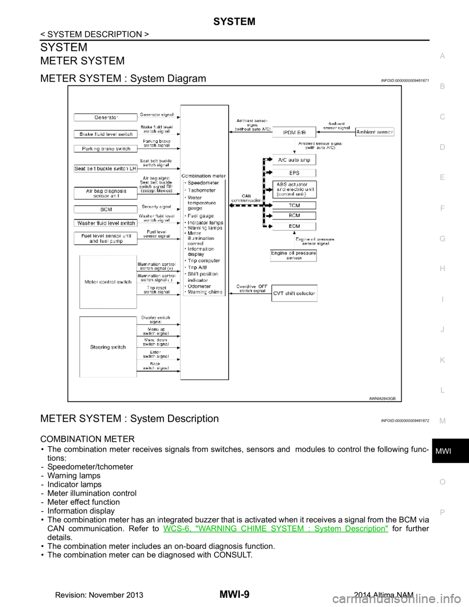
METER SYSTEM : System DiagramINFOID:0000000009461671
METER SYSTEM : System DescriptionINFOID:0000000009461672
COMBINATION METER
• The combination meter receives signals from switches, sensors and modules to control the following func-
tions:
- Speedometer/tchometer
- Warning lamps
- Indicator lamps
- Meter illumination control
- Meter effect function
- Information display
• The combination meter has an integrated buzzer that is activated when it receives a signal from the BCM via
CAN communication. Refer to WCS-6, "WARNING CHIME SYST EM : System Description"
for further
details.
• The combination meter includes an on-board diagnosis function.
• The combination meter can be diagnosed with CONSULT.
AWNIA2643GB
Revision: November 20132014 Altima NAMRevision: November 20132014 Altima NAM
Page 3265 of 4801
MWI-10
< SYSTEM DESCRIPTION >
SYSTEM
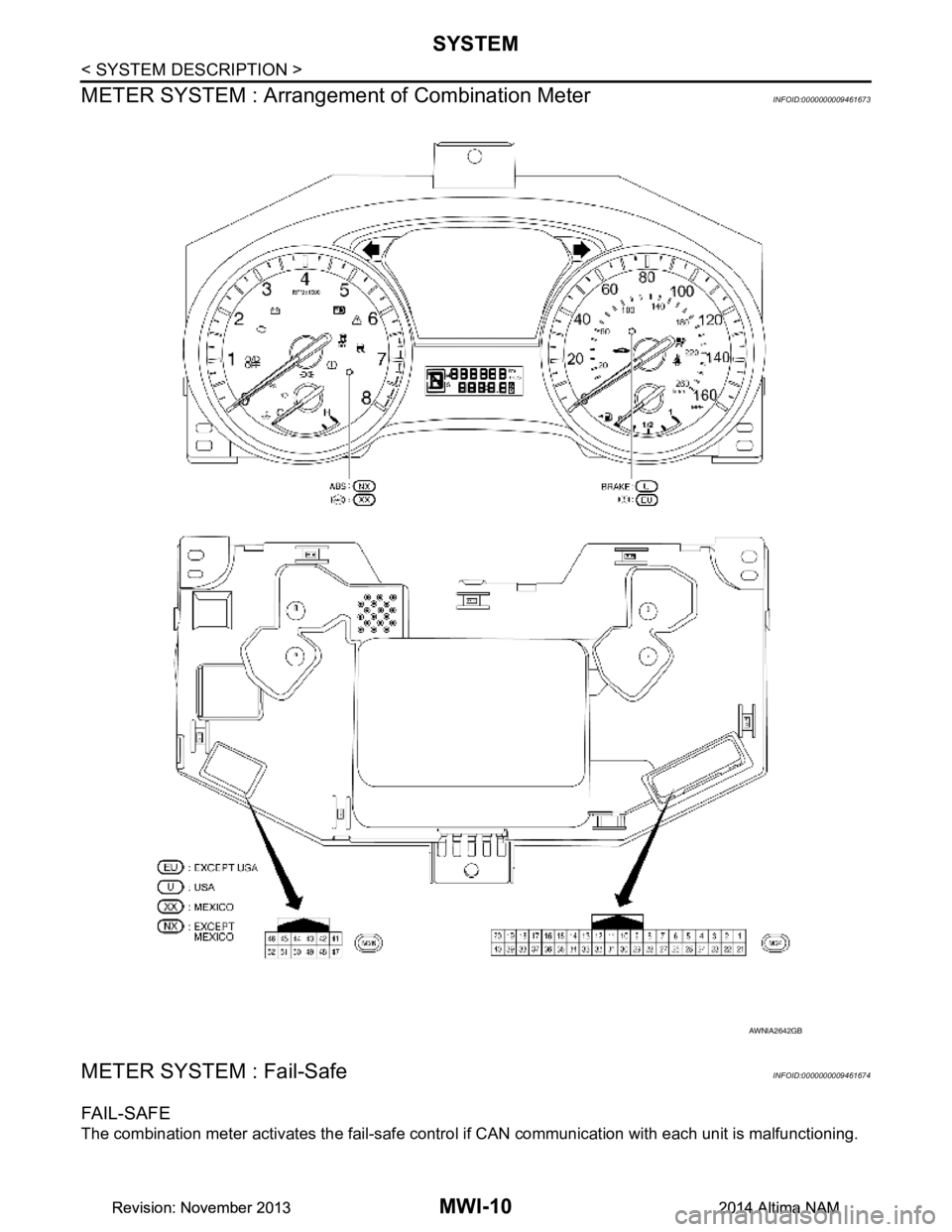
METER SYSTEM : Arrangemen t of Combination Meter
INFOID:0000000009461673
METER SYSTEM : Fail-SafeINFOID:0000000009461674
FA I L - S A F E
The combination meter activates the fail-safe contro l if CAN communication with each unit is malfunctioning.
AWNIA2642GB
Revision: November 20132014 Altima NAMRevision: November 20132014 Altima NAM
Page 3266 of 4801
MWI
SYSTEMMWI-11
< SYSTEM DESCRIPTION >
C
D E
F
G H
I
J
K L
M B
A
O P
SPEEDOMETER
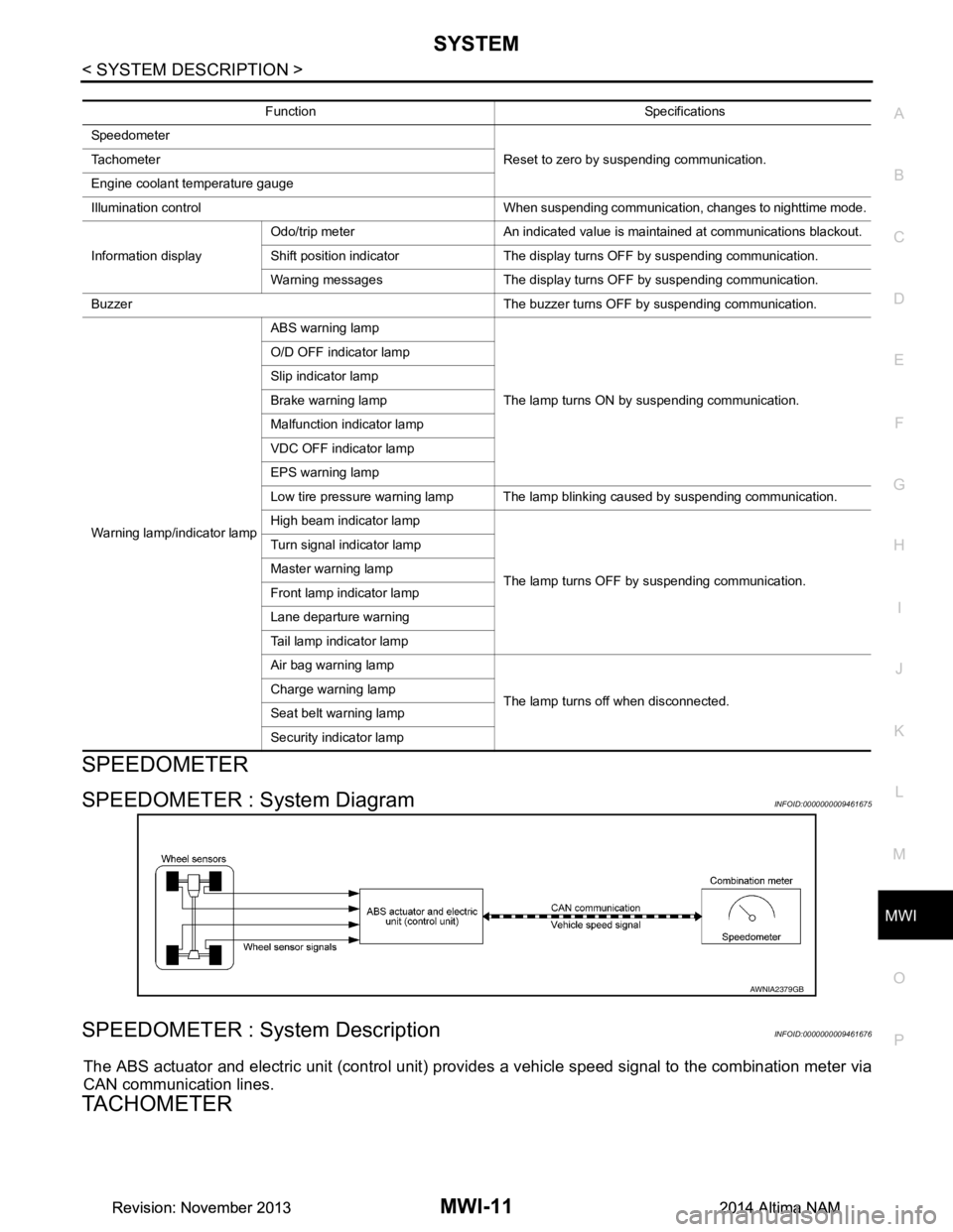
SPEEDOMETER : System DiagramINFOID:0000000009461675
SPEEDOMETER : System DescriptionINFOID:0000000009461676
The ABS actuator and electric unit (control unit) provi des a vehicle speed signal to the combination meter via
CAN communication lines.
TACHOMETER
Function Specifications
Speedometer Reset to zero by suspending communication.
Tachometer
Engine coolant temperature gauge
Illumination control When suspending communication, changes to nighttime mode.
Information display Odo/trip meter An indicated value is maintained at communications blackout.
Shift position indicator The display turns OFF by suspending communication.
Warning messages The display turns OFF by suspending communication.
Buzzer The buzzer turns OFF by suspending communication.
Warning lamp/indicator lamp ABS warning lamp
The lamp turns ON by suspending communication.
O/D OFF indicator lamp
Slip indicator lamp
Brake warning lamp
Malfunction indicator lamp
VDC OFF indicator lamp
EPS warning lamp
Low tire pressure warning lamp The lamp blinking caused by suspending communication.
High beam indicator lamp
The lamp turns OFF by suspending communication.
Turn signal indicator lamp
Master warning lamp
Front lamp indicator lamp
Lane departure warning
Tail lamp indicator lamp
Air bag warning lamp
The lamp turns off when disconnected.
Charge warning lamp
Seat belt warning lamp
Security indicator lamp
AWNIA2379GB
Revision: November 20132014 Altima NAMRevision: November 20132014 Altima NAM
Page 3267 of 4801
MWI-12
< SYSTEM DESCRIPTION >
SYSTEM
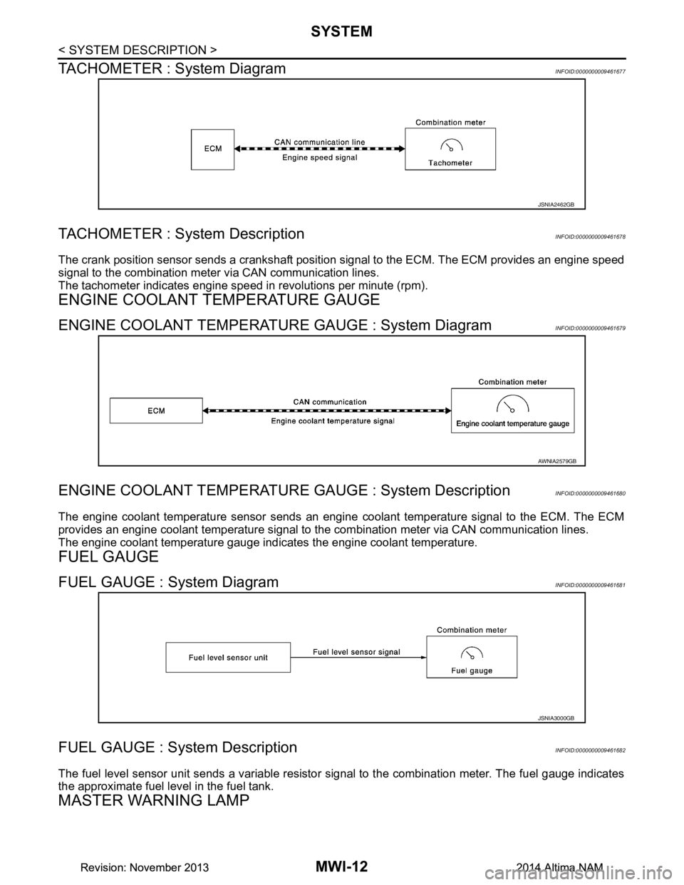
TACHOMETER : System Diagram
INFOID:0000000009461677
TACHOMETER : System DescriptionINFOID:0000000009461678
The crank position sensor sends a crankshaft positi on signal to the ECM. The ECM provides an engine speed
signal to the combination meter via CAN communication lines.
The tachometer indicates engine speed in revolutions per minute (rpm).
ENGINE COOLANT TEMPERATURE GAUGE
ENGINE COOLANT TEMPERATURE GAUGE : System DiagramINFOID:0000000009461679
ENGINE COOLANT TEMPERATURE GAUGE : System DescriptionINFOID:0000000009461680
The engine coolant temperature sensor sends an engine coolant temperature signal to the ECM. The ECM
provides an engine coolant temperature signal to t he combination meter via CAN communication lines.
The engine coolant temperature gauge indicates the engine coolant temperature.
FUEL GAUGE
FUEL GAUGE : System DiagramINFOID:0000000009461681
FUEL GAUGE : System DescriptionINFOID:0000000009461682
The fuel level sensor unit sends a variable resistor signal to the combination meter. The fuel gauge indicates
the approximate fuel level in the fuel tank.
MASTER WARNING LAMP
JSNIA2462GB
AWNIA2579GB
JSNIA3000GB
Revision: November 20132014 Altima NAMRevision: November 20132014 Altima NAM
Page 3268 of 4801
MWI
SYSTEMMWI-13
< SYSTEM DESCRIPTION >
C
D E
F
G H
I
J
K L
M B
A
O P
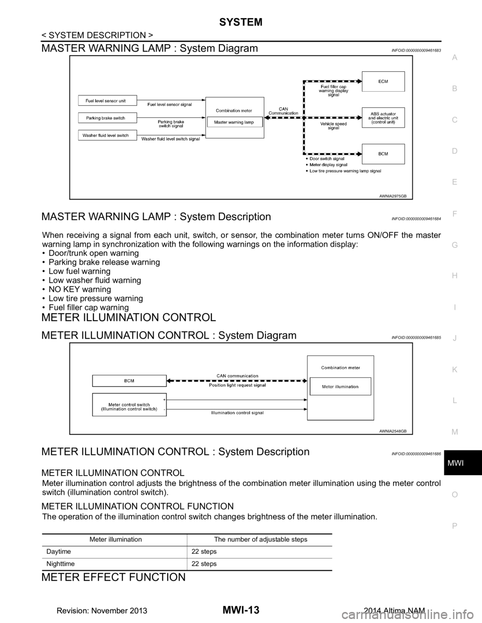
MASTER WARNING LAMP : System DiagramINFOID:0000000009461683
MASTER WARNING LAMP : System DescriptionINFOID:0000000009461684
When receiving a signal from each unit, switch, or s ensor, the combination meter turns ON/OFF the master
warning lamp in synchronization with the following warnings on the information display:
• Door/trunk open warning
• Parking brake release warning
• Low fuel warning
• Low washer fluid warning
• NO KEY warning
• Low tire pressure warning
• Fuel filler cap warning
METER ILLUMINATION CONTROL
METER ILLUMINATION CONTROL : System DiagramINFOID:0000000009461685
METER ILLUMINATION CONTROL : System DescriptionINFOID:0000000009461686
METER ILLUMINATION CONTROL
Meter illumination control adjusts the brightness of the combination meter illumination using the meter control
switch (illumination control switch).
METER ILLUMINATION CONTROL FUNCTION
The operation of the illumination control switch changes brightness of the meter illumination.
METER EFFECT FUNCTION
AWNIA2975GB
AWNIA2548GB
Meter illumination The number of adjustable steps
Daytime 22 steps
Nighttime 22 steps
Revision: November 20132014 Altima NAMRevision: November 20132014 Altima NAM
Page 3269 of 4801
MWI-14
< SYSTEM DESCRIPTION >
SYSTEM
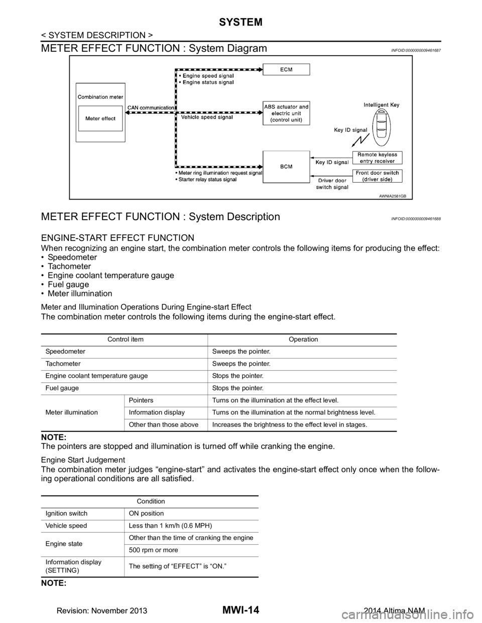
METER EFFECT FUNCTION : System Diagram
INFOID:0000000009461687
METER EFFECT FUNCTION : System DescriptionINFOID:0000000009461688
ENGINE-START EFFECT FUNCTION
When recognizing an engine start, the combination meter c ontrols the following items for producing the effect:
• Speedometer
• Tachometer
• Engine coolant temperature gauge
• Fuel gauge
• Meter illumination
Meter and Illumination Operations During Engine-start Effect
The combination meter controls the following items during the engine-start effect.
NOTE:
The pointers are stopped and illumination is turned off while cranking the engine.
Engine Start Judgement
The combination meter judges “engine-start” and activates the engine-start effect only once when the follow-
ing operational conditions are all satisfied.
NOTE:
AWNIA2581GB
Control item Operation
Speedometer Sweeps the pointer.
Tachometer Sweeps the pointer.
Engine coolant temperature gauge Stops the pointer.
Fuel gauge Stops the pointer.
Meter illumination Pointers Turns on the illumination at the effect level.
Information display Turns on the illumination at the normal brightness level.
Other than those above Increases the brightness to the effect level in stages.
Condition
Ignition switch ON position
Vehicle speed Less than 1 km/h (0.6 MPH)
Engine state Other than the time of cranking the engine
500 rpm or more
Information display
(SETTING) The setting of “EFFECT” is “ON.”
Revision: November 20132014 Altima NAMRevision: November 20132014 Altima NAM
Page 3270 of 4801
MWI
SYSTEMMWI-15
< SYSTEM DESCRIPTION >
C
D E
F
G H
I
J
K L
M B
A
O P
Engine-start effect exits when any of the above operat ional conditions is cancelled during the engine-start
effect.
INFORMATION DISPLAY
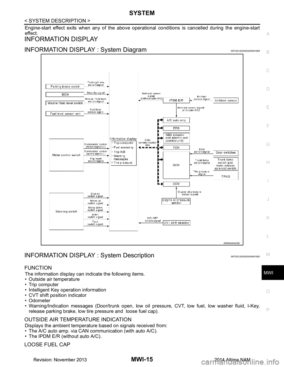
INFORMATION DISPLAY : System DiagramINFOID:0000000009461689
INFORMATION DISPLAY : System DescriptionINFOID:0000000009461690
FUNCTION
The information display can indicate the following items.
• Outside air temperature
• Trip computer
• Intelligent Key operation information
• CVT shift position indicator
• Odometer
• Warning/Indication messages (Door/trunk open, low oil pressure, CVT, low fuel, low washer fluid, I-Key,
release parking brake, low tire pressure and loose fuel cap).
OUTSIDE AIR TEMPERATURE INDICATION
Displays the ambient temperature based on signals received from:
• The A/C auto amp. via CAN communication (with auto A/C).
• The IPDM E/R (without auto A/C).
LOOSE FUEL CAP
AWNIA2645GB
Revision: November 20132014 Altima NAMRevision: November 20132014 Altima NAM