NISSAN TERRANO 2004 Service Repair Manual
Manufacturer: NISSAN, Model Year: 2004, Model line: TERRANO, Model: NISSAN TERRANO 2004Pages: 1833, PDF Size: 53.42 MB
Page 671 of 1833

Wiring Diagram
YEC677A
DTC P0180 FUEL TEMP SENSORTD27Ti
EC-396
http://vnx.su/
Page 672 of 1833
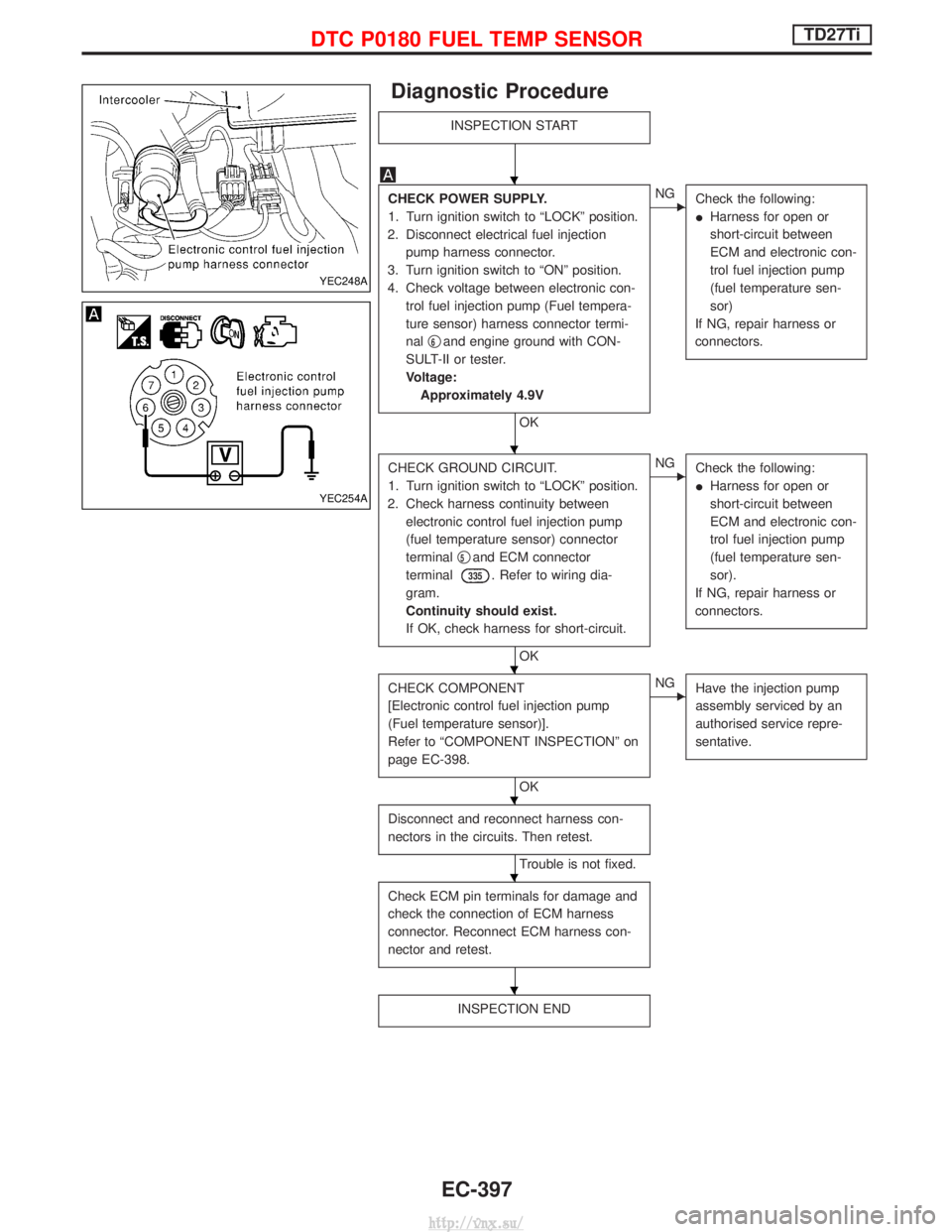
Diagnostic Procedure
INSPECTION START
CHECK POWER SUPPLY.
1. Turn ignition switch to ªLOCKº position.
2. Disconnect electrical fuel injection pump harness connector.
3. Turn ignition switch to ªONº position.
4. Check voltage between electronic con- trol fuel injection pump (Fuel tempera-
ture sensor) harness connector termi-
nal q
6and engine ground with CON-
SULT-II or tester.
Voltage: Approximately 4.9V
OK
ENG Check the following:
IHarness for open or
short-circuit between
ECM and electronic con-
trol fuel injection pump
(fuel temperature sen-
sor)
If NG, repair harness or
connectors.
CHECK GROUND CIRCUIT.
1. Turn ignition switch to ªLOCKº position.
2. Check harness continuity between electronic control fuel injection pump
(fuel temperature sensor) connector
terminal q
5and ECM connector
terminal
335. Refer to wiring dia-
gram.
Continuity should exist.
If OK, check harness for short-circuit.
OK
ENG Check the following:
IHarness for open or
short-circuit between
ECM and electronic con-
trol fuel injection pump
(fuel temperature sen-
sor).
If NG, repair harness or
connectors.
CHECK COMPONENT
[Electronic control fuel injection pump
(Fuel temperature sensor)].
Refer to ªCOMPONENT INSPECTIONº on
page EC-398.
OK
ENG Have the injection pump
assembly serviced by an
authorised service repre-
sentative.
Disconnect and reconnect harness con-
nectors in the circuits. Then retest.
Trouble is not fixed.
Check ECM pin terminals for damage and
check the connection of ECM harness
connector. Reconnect ECM harness con-
nector and retest.
INSPECTION END
YEC248A
YEC254A
H
H
H
H
H
H
DTC P0180 FUEL TEMP SENSORTD27Ti
EC-397
http://vnx.su/
Page 673 of 1833
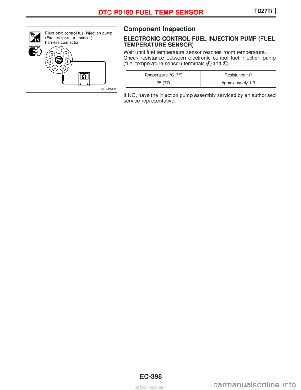
Component Inspection
ELECTRONIC CONTROL FUEL INJECTION PUMP (FUEL
TEMPERATURE SENSOR)
Wait until fuel temperature sensor reaches room temperature.
Check resistance between electronic control fuel injection pump
(fuel temperature sensor) terminalsq
5andq6.
Temperature ÉC (ÉF)
Resistance kW
25 (77) Approximately 1.9
If NG, have the injection pump assembly serviced by an authorised
service representative.
YEC255A
DTC P0180 FUEL TEMP SENSORTD27Ti
EC-398
http://vnx.su/
Page 674 of 1833
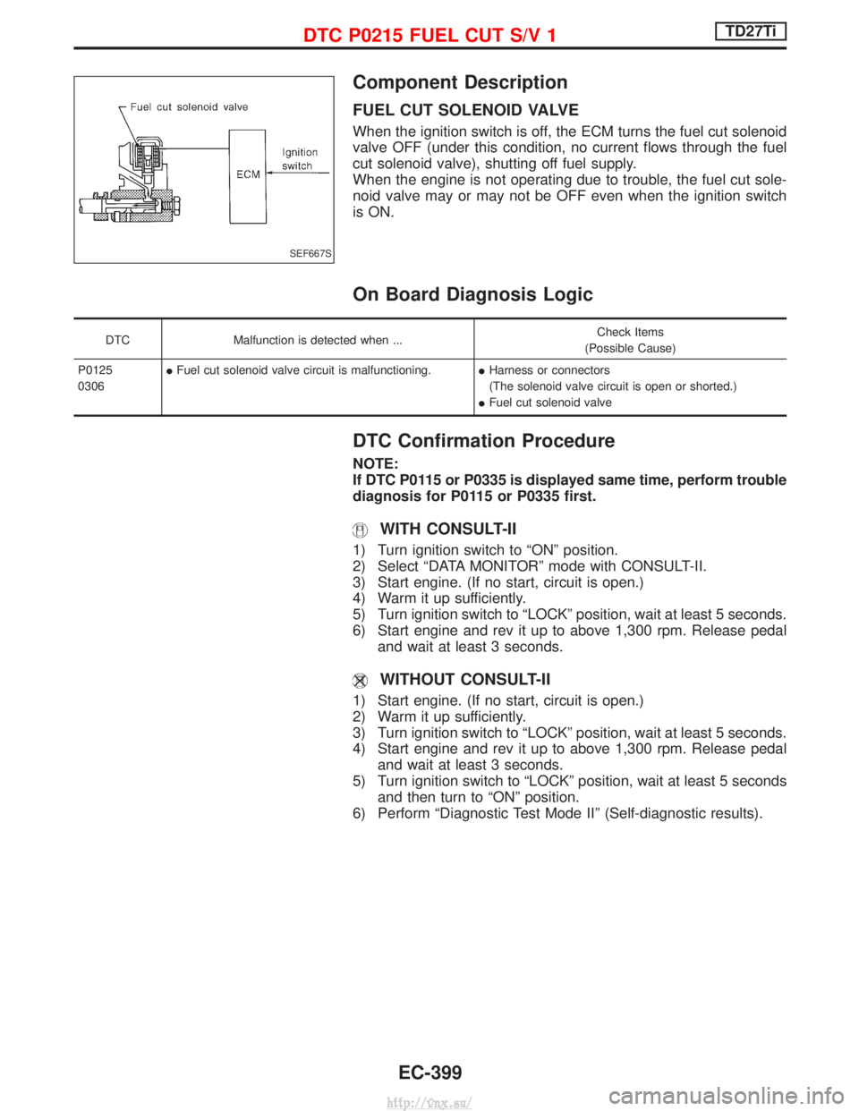
Component Description
FUEL CUT SOLENOID VALVE
When the ignition switch is off, the ECM turns the fuel cut solenoid
valve OFF (under this condition, no current flows through the fuel
cut solenoid valve), shutting off fuel supply.
When the engine is not operating due to trouble, the fuel cut sole-
noid valve may or may not be OFF even when the ignition switch
is ON.
On Board Diagnosis Logic
DTCMalfunction is detected when ... Check Items
(Possible Cause)
P0125
0306 I
Fuel cut solenoid valve circuit is malfunctioning. IHarness or connectors
(The solenoid valve circuit is open or shorted.)
I Fuel cut solenoid valve
DTC Confirmation Procedure
NOTE:
If DTC P0115 or P0335 is displayed same time, perform trouble
diagnosis for P0115 or P0335 first.
WITH CONSULT-II
1) Turn ignition switch to ªONº position.
2) Select ªDATA MONITORº mode with CONSULT-II.
3) Start engine. (If no start, circuit is open.)
4) Warm it up sufficiently.
5) Turn ignition switch to ªLOCKº position, wait at least 5 seconds.
6) Start engine and rev it up to above 1,300 rpm. Release pedal
and wait at least 3 seconds.
WITHOUT CONSULT-II
1) Start engine. (If no start, circuit is open.)
2) Warm it up sufficiently.
3) Turn ignition switch to ªLOCKº position, wait at least 5 seconds.
4) Start engine and rev it up to above 1,300 rpm. Release pedaland wait at least 3 seconds.
5) Turn ignition switch to ªLOCKº position, wait at least 5 seconds and then turn to ªONº position.
6) Perform ªDiagnostic Test Mode IIº (Self-diagnostic results).
SEF667S
DTC P0215 FUEL CUT S/V 1TD27Ti
EC-399
http://vnx.su/
Page 675 of 1833

Wiring Diagram
YEC678A
DTC P0215 FUEL CUT S/V 1TD27Ti
EC-400
http://vnx.su/
Page 676 of 1833
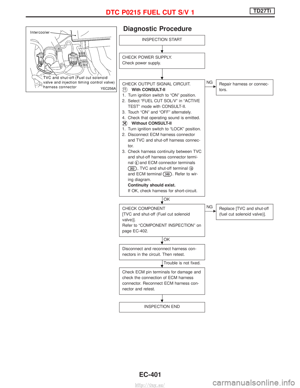
Diagnostic Procedure
INSPECTION START
CHECK POWER SUPPLY.
Check power supply.
CHECK OUTPUT SIGNAL CIRCUIT.
With CONSULT-II
1. Turn ignition switch to ªONº position.
2. Select ªFUEL CUT SOL/Vº in ªACTIVE TESTº mode with CONSULT-II.
3. Touch ªONº and ªOFFº alternately.
4. Check that operating sound is emitted.
Without CONSULT-II
1. Turn ignition switch to ªLOCKº position.
2. Disconnect ECM harness connector and TVC and shut-off harness connec-
tor.
3. Check harness continuity between TVC and shut-off harness connector termi-
nal q
8and ECM connector terminals
202, TVC and shut-off terminal q10
and ECM terminal349. Refer to wir-
ing diagram.
Continuity should exist.
If OK, check harness for short-circuit.
OK
ENG Repair harness or connec-
tors.
CHECK COMPONENT
[TVC and shut-off (Fuel cut solenoid
valve)].
Refer to ªCOMPONENT INSPECTIONº on
page EC-402.
OK
ENGReplace [TVC and shut-off
(fuel cut solenoid valve)].
Disconnect and reconnect harness con-
nectors in the circuit. Then retest.
Trouble is not fixed.
Check ECM pin terminals for damage and
check the connection of ECM harness
connector. Reconnect ECM harness con-
nector and retest.
INSPECTION END
YEC256A
H
H
H
H
H
H
DTC P0215 FUEL CUT S/V 1TD27Ti
EC-401
http://vnx.su/
Page 677 of 1833
![NISSAN TERRANO 2004 Service Repair Manual Component Inspection
[TVC AND SHUT OFF (FUEL CUT SOLENOID VALVE)]
1. Remove TVC and shut-off (fuel cut solenoid valve) harnessconnector.
2. Check that operating sound is emitted when applying 12V dire NISSAN TERRANO 2004 Service Repair Manual Component Inspection
[TVC AND SHUT OFF (FUEL CUT SOLENOID VALVE)]
1. Remove TVC and shut-off (fuel cut solenoid valve) harnessconnector.
2. Check that operating sound is emitted when applying 12V dire](/img/5/57394/w960_57394-676.png)
Component Inspection
[TVC AND SHUT OFF (FUEL CUT SOLENOID VALVE)]
1. Remove TVC and shut-off (fuel cut solenoid valve) harnessconnector.
2. Check that operating sound is emitted when applying 12V direct current to terminal q
9andq8.
If NG, replace TVC and shut-off (fuel cut solenoid valve).
MEC963D
DTC P0215 FUEL CUT S/V 1TD27Ti
EC-402
http://vnx.su/
Page 678 of 1833
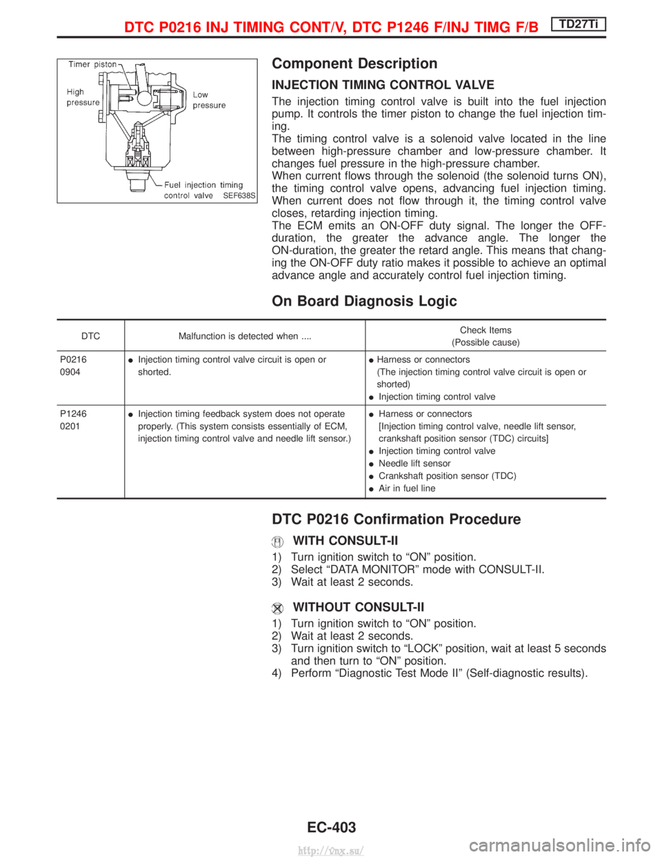
Component Description
INJECTION TIMING CONTROL VALVE
The injection timing control valve is built into the fuel injection
pump. It controls the timer piston to change the fuel injection tim-
ing.
The timing control valve is a solenoid valve located in the line
between high-pressure chamber and low-pressure chamber. It
changes fuel pressure in the high-pressure chamber.
When current flows through the solenoid (the solenoid turns ON),
the timing control valve opens, advancing fuel injection timing.
When current does not flow through it, the timing control valve
closes, retarding injection timing.
The ECM emits an ON-OFF duty signal. The longer the OFF-
duration, the greater the advance angle. The longer the
ON-duration, the greater the retard angle. This means that chang-
ing the ON-OFF duty ratio makes it possible to achieve an optimal
advance angle and accurately control fuel injection timing.
On Board Diagnosis Logic
DTCMalfunction is detected when .... Check Items
(Possible cause)
P0216
0904 I
Injection timing control valve circuit is open or
shorted. I
Harness or connectors
(The injection timing control valve circuit is open or
shorted)
I Injection timing control valve
P1246
0201 I
Injection timing feedback system does not operate
properly. (This system consists essentially of ECM,
injection timing control valve and needle lift sensor.) I
Harness or connectors
[Injection timing control valve, needle lift sensor,
crankshaft position sensor (TDC) circuits]
I Injection timing control valve
I Needle lift sensor
I Crankshaft position sensor (TDC)
I Air in fuel line
DTC P0216 Confirmation Procedure
WITH CONSULT-II
1) Turn ignition switch to ªONº position.
2) Select ªDATA MONITORº mode with CONSULT-II.
3) Wait at least 2 seconds.
WITHOUT CONSULT-II
1) Turn ignition switch to ªONº position.
2) Wait at least 2 seconds.
3) Turn ignition switch to ªLOCKº position, wait at least 5 seconds
and then turn to ªONº position.
4) Perform ªDiagnostic Test Mode IIº (Self-diagnostic results).
SEF638S
DTC P0216 INJ TIMING CONT/V, DTC P1246 F/INJ TIMG F/BTD27Ti
EC-403
http://vnx.su/
Page 679 of 1833
DTC P1246 Confirmation Procedure
NOTE:
If both DTC P1246 and P1240 or P0335 are displayed, perform
TROUBLE DIAGNOSIS FOR DTC P1240 or P0335. (See EC-450
or EC-408.)
WITH CONSULT-II
1) Turn ignition switch to ªONº position and select ªDATA MONI-TORº mode with CONSULT-II.
2) Start engine. Run it for 10 seconds at idle.
WITHOUT CONSULT-II
1) Start engine. Run it for 10 seconds at idle.
2) Turn ignition switch to ªLOCKº position, wait at least 5 seconds and then turn to ªONº position.
3) Perform ªDiagnostic Test Mode IIº (Self-diagnostic results).
NOTE:
If a malfunction occurs intermittently, conduct suitable driving
pattern for 10 minutes. This makes it possible to determine
DTC.
DTC P0216 INJ TIMING CONT/V, DTC P1246 F/INJ TIMG F/BTD27Ti
EC-404
http://vnx.su/
Page 680 of 1833

Wiring Diagram
YEC678A
DTC P0216 INJ TIMING CONT/V, DTC P1246 F/INJ TIMG F/BTD27Ti
EC-405
http://vnx.su/