timing belt NISSAN TIIDA 2007 Service Owner's Manual
[x] Cancel search | Manufacturer: NISSAN, Model Year: 2007, Model line: TIIDA, Model: NISSAN TIIDA 2007Pages: 5883, PDF Size: 78.95 MB
Page 2725 of 5883
EM-78
< ON-VEHICLE REPAIR >[HR16DE]
OIL SEAL
FRONT OIL SEAL : Removal and Installation
INFOID:0000000001381418
REMOVAL
1. Remove the following parts:
Front fender protector (RH): Refer to EXT-22, "
Removal and Installation".
Drive belt: Refer to EM-16, "
Removal and Installation".
Crankshaft pulley: Refer to EM-50, "
Exploded View".
2. Remove front oil seal using a suitable tool.
CAUTION:
Be careful not to damage front timing chain case and crankshaft.
INSTALLATION
1. Apply new engine oil to both oil seal lip and dust seal lip of new front oil seal.
2. Install front oil seal.
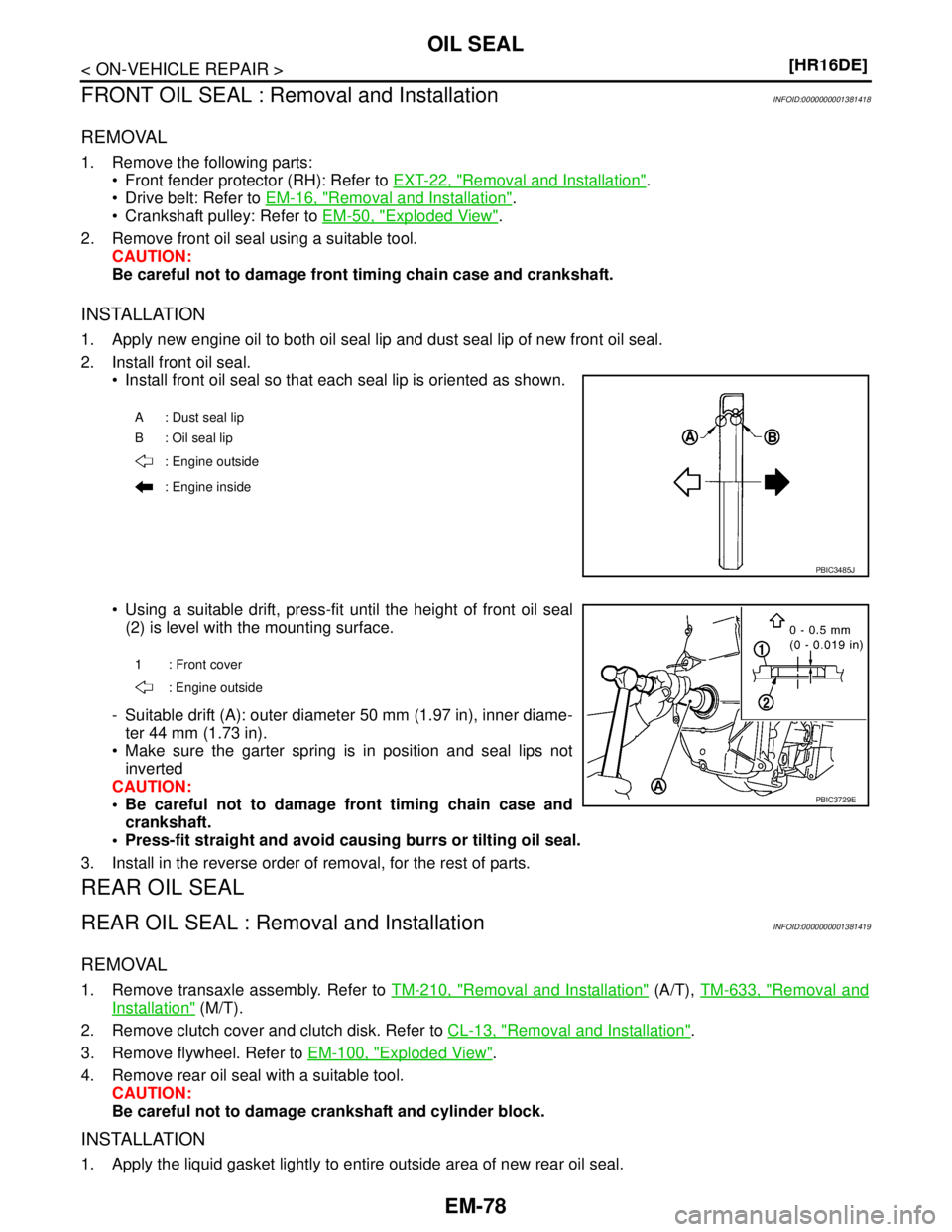
Install front oil seal so that each seal lip is oriented as shown.
Using a suitable drift, press-fit until the height of front oil seal
(2) is level with the mounting surface.
- Suitable drift (A): outer diameter 50 mm (1.97 in), inner diame-
ter 44 mm (1.73 in).
Make sure the garter spring is in position and seal lips not
inverted
CAUTION:
Be careful not to damage front timing chain case and
crankshaft.
Press-fit straight and avoid causing burrs or tilting oil seal.
3. Install in the reverse order of removal, for the rest of parts.
REAR OIL SEAL
REAR OIL SEAL : Removal and InstallationINFOID:0000000001381419
REMOVAL
1. Remove transaxle assembly. Refer to TM-210, "Removal and Installation" (A/T), TM-633, "Removal and
Installation" (M/T).
2. Remove clutch cover and clutch disk. Refer to CL-13, "
Removal and Installation".
3. Remove flywheel. Refer to EM-100, "
Exploded View".
4. Remove rear oil seal with a suitable tool.
CAUTION:
Be careful not to damage crankshaft and cylinder block.
INSTALLATION
1. Apply the liquid gasket lightly to entire outside area of new rear oil seal.
A : Dust seal lip
B: Oil seal lip
: Engine outside
: Engine inside
PBIC3485J
1 : Front cover
: Engine outside
PBIC3729E
Page 2769 of 5883
EM-122
< SERVICE DATA AND SPECIFICATIONS (SDS) [HR16DE]
SERVICE DATA AND SPECIFICATIONS (SDS)
SERVICE DATA AND SPECIFICATIONS (SDS)
SERVICE DATA AND SPECIFICATIONS (SDS)
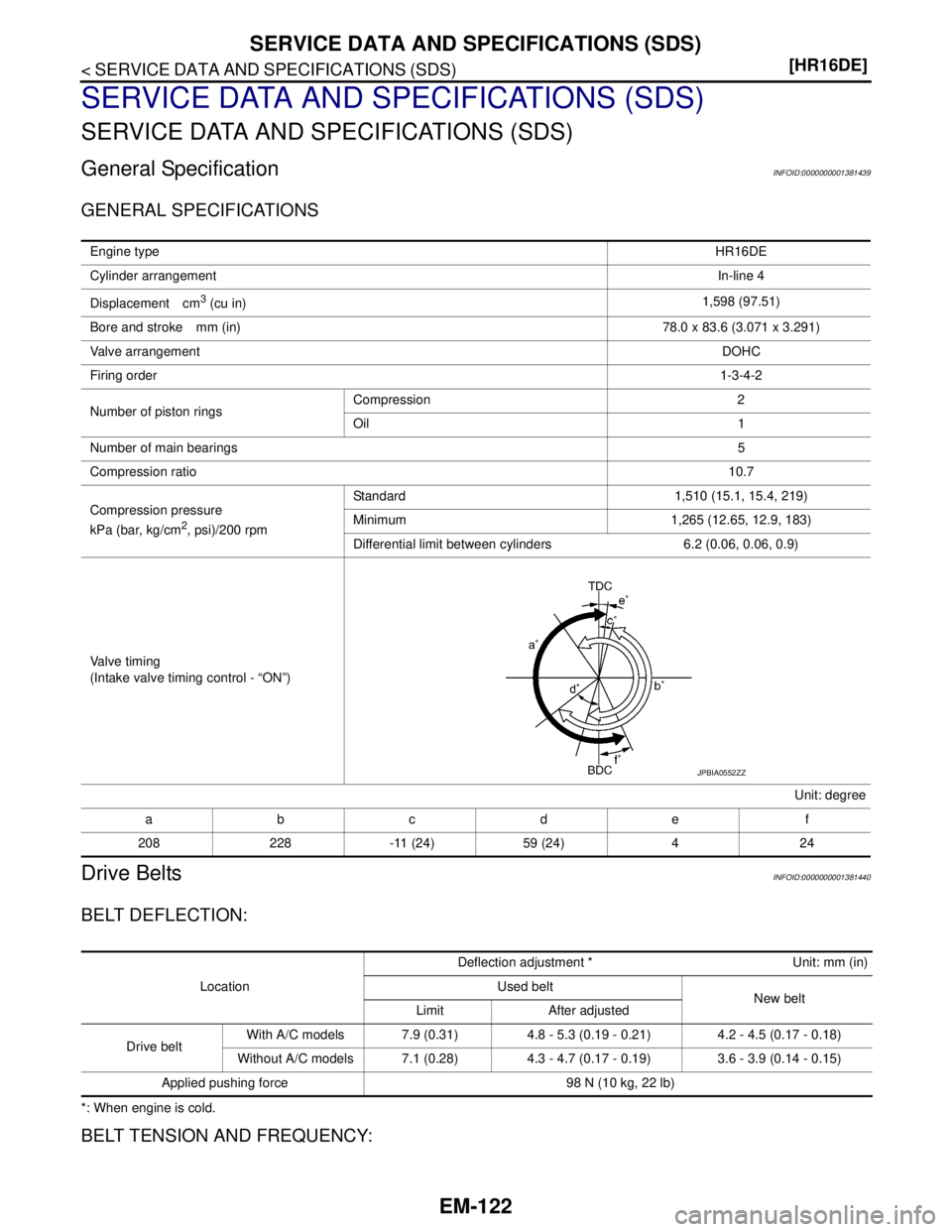
General SpecificationINFOID:0000000001381439
GENERAL SPECIFICATIONS
Drive BeltsINFOID:0000000001381440
BELT DEFLECTION:
*: When engine is cold.
BELT TENSION AND FREQUENCY:
Engine typeHR16DE
Cylinder arrangementIn-line 4
Displacement cm
3 (cu in)1,598 (97.51)
Bore and stroke mm (in)78.0 x 83.6 (3.071 x 3.291)
Valve arrangementDOHC
Firing order1-3-4-2
Number of piston ringsCompression 2
Oil 1
Number of main bearings5
Compression ratio10.7
Compression pressure
kPa (bar, kg/cm
2, psi)/200 rpmStandard 1,510 (15.1, 15.4, 219)
Minimum 1,265 (12.65, 12.9, 183)
Differential limit between cylinders 6.2 (0.06, 0.06, 0.9)
Valve timing
(Intake valve timing control - “ON”)
Unit: degree
abcde f
208 228 -11 (24) 59 (24) 4 24
JPBIA0552ZZ
LocationDeflection adjustment * Unit: mm (in)
Used belt
New belt
Limit After adjusted
Drive beltWith A/C models 7.9 (0.31) 4.8 - 5.3 (0.19 - 0.21) 4.2 - 4.5 (0.17 - 0.18)
Without A/C models 7.1 (0.28) 4.3 - 4.7 (0.17 - 0.19) 3.6 - 3.9 (0.14 - 0.15)
Applied pushing force 98 N (10 kg, 22 lb)
Page 2779 of 5883
EM-132
< SYMPTOM DIAGNOSIS >[MR18DE]
NOISE, VIBRATION AND HARSHNESS (NVH) TROUBLESHOOTING
SYMPTOM DIAGNOSIS
NOISE, VIBRATION AND HARSHNESS (NVH) TROUBLESHOOTING
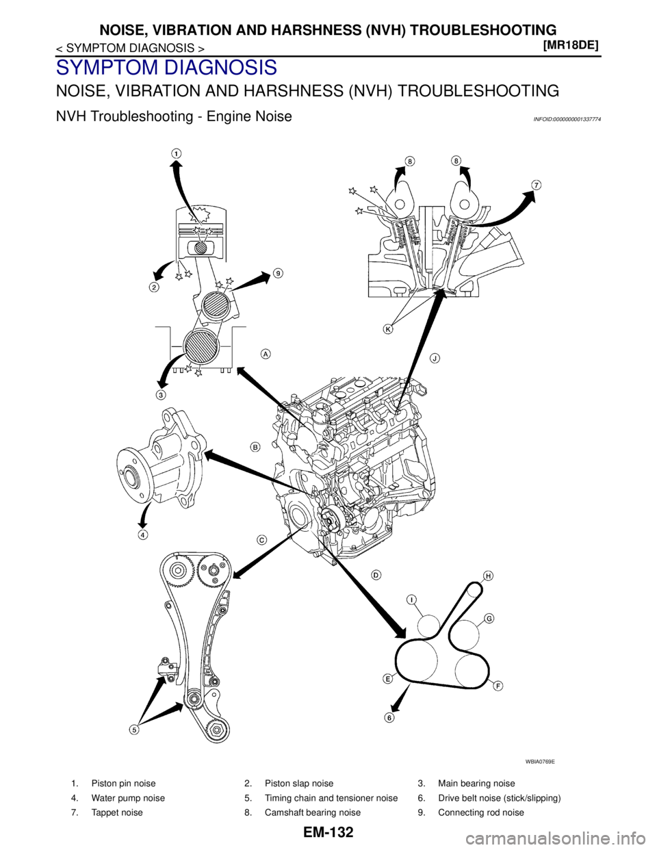
NVH Troubleshooting - Engine NoiseINFOID:0000000001337774
WBIA0769E
1. Piston pin noise 2. Piston slap noise 3. Main bearing noise
4. Water pump noise 5. Timing chain and tensioner noise 6. Drive belt noise (stick/slipping)
7. Tappet noise 8. Camshaft bearing noise 9. Connecting rod noise
Page 2780 of 5883
NOISE, VIBRATION AND HARSHNESS (NVH) TROUBLESHOOTING
EM-133
< SYMPTOM DIAGNOSIS >[MR18DE]
C
D
E
F
G
H
I
J
K
L
MA
EM
N
P O
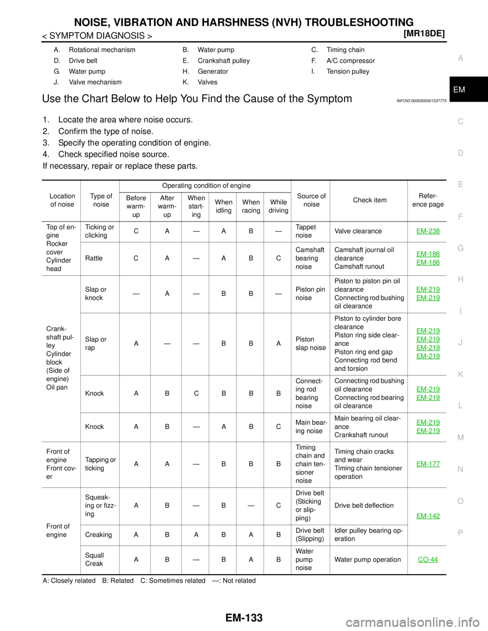
Use the Chart Below to Help You Find the Cause of the SymptomINFOID:0000000001337775
1. Locate the area where noise occurs.
2. Confirm the type of noise.
3. Specify the operating condition of engine.
4. Check specified noise source.
If necessary, repair or replace these parts.
A: Closely related B: Related C: Sometimes related —: Not relatedA. Rotational mechanism B. Water pump C. Timing chain
D. Drive belt E. Crankshaft pulley F. A/C compressor
G. Water pump H. Generator I. Tension pulley
J. Valve mechanism K. Valves
Location
of noiseType of
noiseOperating condition of engine
Source of
noiseCheck itemRefer-
ence page Before
warm-
upAfter
warm-
upWhen
start-
ingWhen
idlingWhen
racingWhile
driving
Top of en-
gine
Rocker
cover
Cylinder
headTicking or
clickingCA—AB—Tappet
noiseValve clearanceEM-238
Rattle C A — A B CCamshaft
bearing
noiseCamshaft journal oil
clearance
Camshaft runoutEM-186EM-186
Crank-
shaft pul-
ley
Cylinder
block
(Side of
engine)
Oil panSlap or
knock—A—BB—Piston pin
noisePiston to piston pin oil
clearance
Connecting rod bushing
oil clearanceEM-219
EM-219
Slap or
rapA——BBAPiston
slap noisePiston to cylinder bore
clearance
Piston ring side clear-
ance
Piston ring end gap
Connecting rod bend
and torsionEM-219EM-219
EM-219
EM-219
Knock A B C B B BConnect-
ing rod
bearing
noiseConnecting rod bushing
oil clearance
Connecting rod bearing
oil clearanceEM-219EM-219
Knock A B — A B CMain bear-
ing noiseMain bearing oil clear-
ance
Crankshaft runoutEM-219EM-219
Front of
engine
Front cov-
erTapping or
tickingAA—BBBTiming
chain and
chain ten-
sioner
noiseTiming chain cracks
and wear
Timing chain tensioner
operationEM-177
Front of
engineSqueak-
ing or fizz-
ingAB—B—CDrive belt
(Sticking
or slip-
ping)Drive belt deflection
EM-142
CreakingA B ABABDrive belt
(Slipping)Idler pulley bearing op-
eration
Squall
CreakAB—BABWater
pump
noiseWater pump operationCO-44
Page 2823 of 5883
EM-176
< ON-VEHICLE REPAIR >[MR18DE]
TIMING CHAIN
TIMING CHAIN
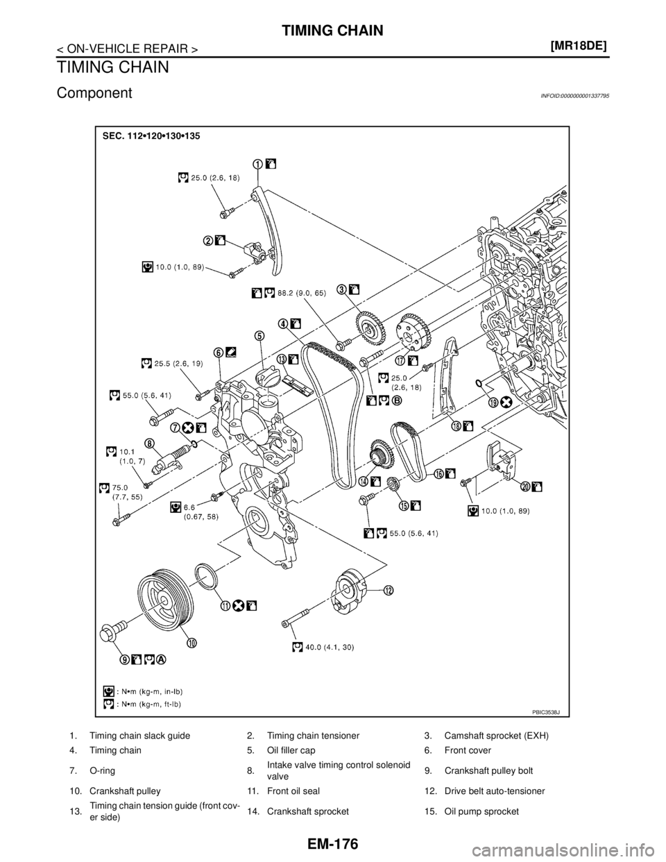
ComponentINFOID:0000000001337795
1. Timing chain slack guide 2. Timing chain tensioner 3. Camshaft sprocket (EXH)
4. Timing chain 5. Oil filler cap 6. Front cover
7. O-ring 8.Intake valve timing control solenoid
valve9. Crankshaft pulley bolt
10. Crankshaft pulley 11. Front oil seal 12. Drive belt auto-tensioner
13.Timing chain tension guide (front cov-
er side)14. Crankshaft sprocket 15. Oil pump sprocket
PBIC3538J
Page 2824 of 5883
TIMING CHAIN
EM-177
< ON-VEHICLE REPAIR >[MR18DE]
C
D
E
F
G
H
I
J
K
L
MA
EM
N
P ORemoval and InstallationINFOID:0000000001337796
CAUTION:
The rotating direction indicated in the text indicates all directions seen from the engine front.
REMOVAL
1. Remove front RH wheel. Refer to WT-6, "Rotation".
2. Remove front fender protector (RH). Refer to EXT-22, "
Removal and Installation".
3. Drain engine oil. Refer to LU-16, "
Changing Engine Oil".
NOTE:
Perform this step when engine is cold.
4. Remove the following parts.
Rocker cover: Refer to EM-173, "
Removal and Installation".
Drive belt: Refer to EM-142, "
Component".
Water pump pulley: Refer to CO-44, "
Component".
Ground cable (between engine bracket (RH) and radiator core support)
5. Support the bottom surface of engine using a transmission jack, and then remove the engine bracket and
insulator (RH). Refer to EM-207
.
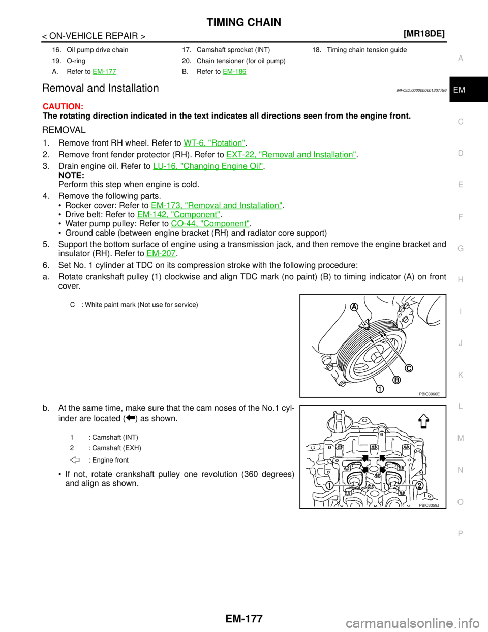
6. Set No. 1 cylinder at TDC on its compression stroke with the following procedure:
a. Rotate crankshaft pulley (1) clockwise and align TDC mark (no paint) (B) to timing indicator (A) on front
cover.
b. At the same time, make sure that the cam noses of the No.1 cyl-
inder are located ( ) as shown.
If not, rotate crankshaft pulley one revolution (360 degrees)
and align as shown.
16. Oil pump drive chain 17. Camshaft sprocket (INT) 18. Timing chain tension guide
19. O-ring 20. Chain tensioner (for oil pump)
A. Refer to EM-177
B. Refer to EM-186
C : White paint mark (Not use for service)
PBIC3960E
1 : Camshaft (INT)
2 : Camshaft (EXH)
: Engine front
PBIC3359J
Page 2825 of 5883
EM-178
< ON-VEHICLE REPAIR >[MR18DE]
TIMING CHAIN
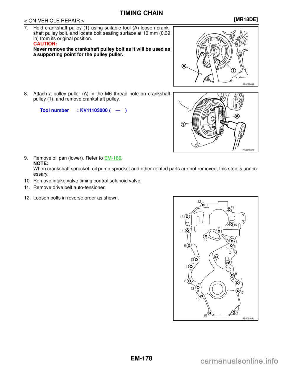
7. Hold crankshaft pulley (1) using suitable tool (A) loosen crank-
shaft pulley bolt, and locate bolt seating surface at 10 mm (0.39
in) from its original position.
CAUTION:
Never remove the crankshaft pulley bolt as it will be used as
a supporting point for the pulley puller.
8. Attach a pulley puller (A) in the M6 thread hole on crankshaft
pulley (1), and remove crankshaft pulley.
9. Remove oil pan (lower). Refer to EM-166
.
NOTE:
When crankshaft sprocket, oil pump sprocket and other related parts are not removed, this step is unnec-
essary.
10. Remove intake valve timing control solenoid valve.
11. Remove drive belt auto-tensioner.
12. Loosen bolts in reverse order as shown.
PBIC3961E
Tool number : KV11103000 ( — )
PBIC3962E
PBIC3164J
Page 2841 of 5883
EM-194
< ON-VEHICLE REPAIR >[MR18DE]
CAMSHAFT
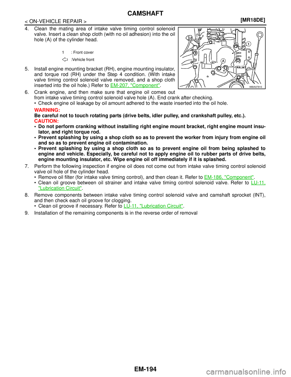
4. Clean the mating area of intake valve timing control solenoid
valve. Insert a clean shop cloth (with no oil adhesion) into the oil
hole (A) of the cylinder head.
5. Install engine mounting bracket (RH), engine mounting insulator,
and torque rod (RH) under the Step 4 condition. (With intake
valve timing control solenoid valve removed, and a shop cloth
inserted into the oil hole.) Refer to EM-207, "
Component".
6. Crank engine, and then make sure that engine oil comes out
from intake valve timing control solenoid valve hole (A). End crank after checking.
Check engine oil leakage by oil amount adhered to the waste inserted into the oil hole.
WARNING:
Be careful not to touch rotating parts (drive belts, idler pulley, and crankshaft pulley, etc.).
CAUTION:
Do not perform cranking without installing right engine mount bracket, right engine mount insu-
lator, and right torque rod.
Prevent splashing by using a shop cloth so as to prevent the worker from injury from engine oil
and so as to prevent engine oil contamination.
Prevent splashing by using a shop cloth so as to prevent engine oil from being splashed to
engine and vehicle. Especially, be careful not to apply engine oil to rubber parts of drive belts,
engine mounting insulator, etc. Wipe engine oil off immediately if it is splashed.
7. Perform the following inspection if engine oil does not come out from intake valve timing control solenoid
valve oil hole of the cylinder head.
Remove oil filter (for intake valve timing control), and then clean it. Refer to EM-186, "
Component".
Clean oil groove between oil strainer and intake valve timing control solenoid valve. Refer to LU-11,
"Lubrication Circuit".
8. Remove components between intake valve timing control solenoid valve and camshaft sprocket (INT),
and then check each oil groove for clogging.
Clean oil groove if necessary. Refer to LU-11, "
Lubrication Circuit".
9. Installation of the remaining components is in the reverse order of removal
1 : Front cover
:Vehicle front
WBIA0781E
Page 2845 of 5883
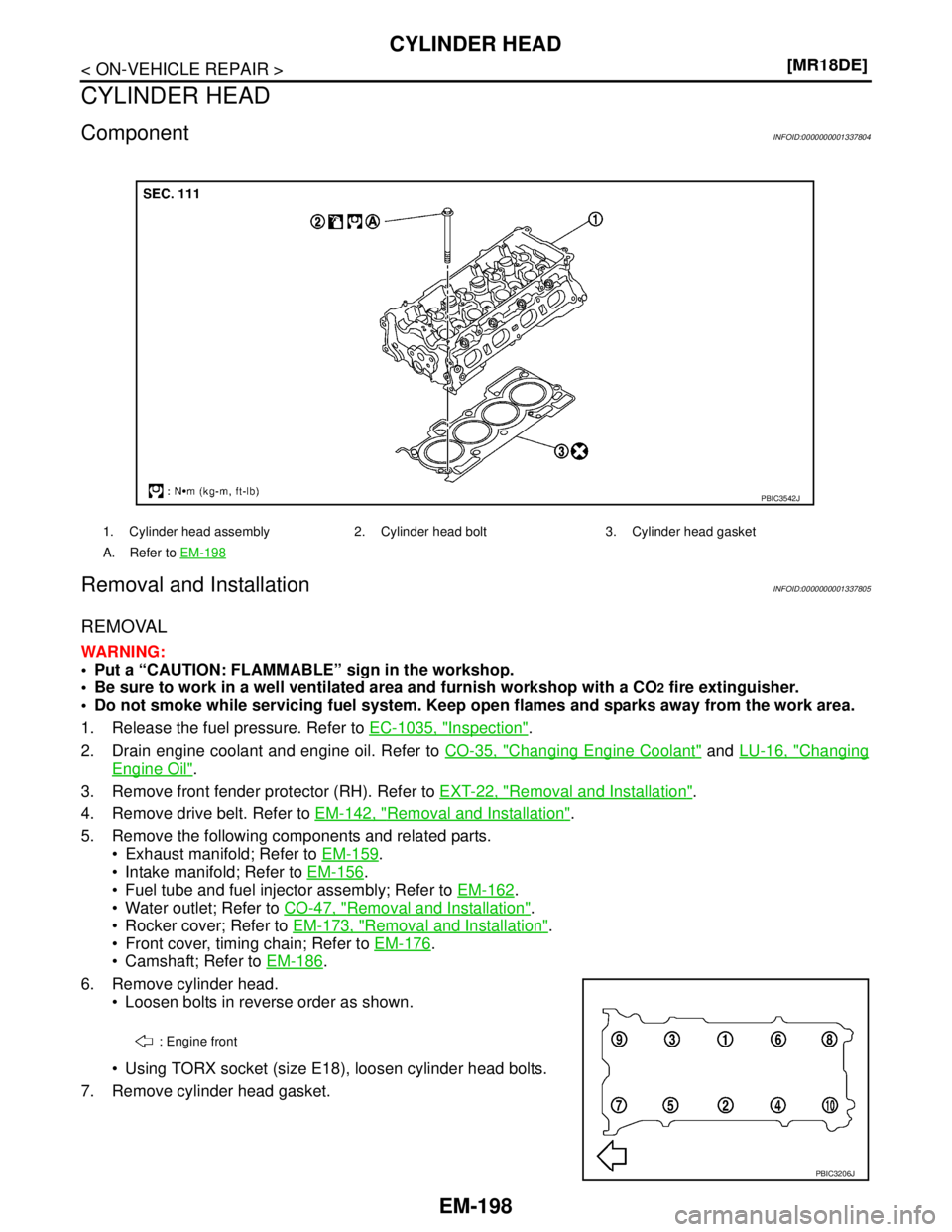
EM-198
< ON-VEHICLE REPAIR >[MR18DE]
CYLINDER HEAD
CYLINDER HEAD
ComponentINFOID:0000000001337804
Removal and InstallationINFOID:0000000001337805
REMOVAL
WARNING:
Put a “CAUTION: FLAMMABLE” sign in the workshop.
Be sure to work in a well ventilated area and furnish workshop with a CO
2 fire extinguisher.
Do not smoke while servicing fuel system. Keep open flames and sparks away from the work area.
1. Release the fuel pressure. Refer to EC-1035, "
Inspection".
2. Drain engine coolant and engine oil. Refer to CO-35, "
Changing Engine Coolant" and LU-16, "Changing
Engine Oil".
3. Remove front fender protector (RH). Refer to EXT-22, "
Removal and Installation".
4. Remove drive belt. Refer to EM-142, "
Removal and Installation".
5. Remove the following components and related parts.
Exhaust manifold; Refer to EM-159
.
Intake manifold; Refer to EM-156
.
Fuel tube and fuel injector assembly; Refer to EM-162
.
Water outlet; Refer to CO-47, "
Removal and Installation".
Rocker cover; Refer to EM-173, "
Removal and Installation".
Front cover, timing chain; Refer to EM-176
.
Camshaft; Refer to EM-186
.
6. Remove cylinder head.
Loosen bolts in reverse order as shown.
Using TORX socket (size E18), loosen cylinder head bolts.
7. Remove cylinder head gasket.
1. Cylinder head assembly 2. Cylinder head bolt 3. Cylinder head gasket
A. Refer to EM-198
PBIC3542J
: Engine front
PBIC3206J
Page 2897 of 5883
EM-250
< SYMPTOM DIAGNOSIS >[K9K]
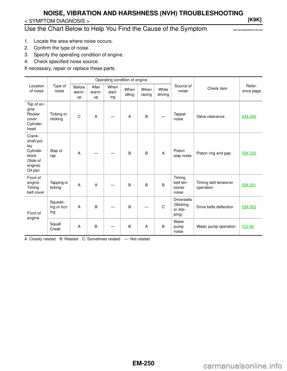
NOISE, VIBRATION AND HARSHNESS (NVH) TROUBLESHOOTING
Use the Chart Below to Help You Find the Cause of the Symptom
INFOID:0000000001381449
1. Locate the area where noise occurs.
2. Confirm the type of noise.
3. Specify the operating condition of engine.
4. Check specified noise source.
If necessary, repair or replace these parts.
A: Closely related B: Related C: Sometimes related —: Not relatedLocation
of noiseType of
noiseOperating condition of engine
Source of
noiseCheck itemRefer-
ence page Before
warm-
upAfter
warm-
upWhen
start-
ingWhen
idlingWhen
racingWhile
driving
Top of en-
gine
Rocker
cover
Cylinder
headTicking or
clickingCA—AB—Tappet
noiseValve clearanceEM-266
Crank-
shaft pul-
ley
Cylinder
block
(Side of
engine)
Oil panSlap or
rapA——B B APiston
slap noisePiston ring end gapEM-330
Front of
engine
Timing
belt coverTapping or
tickingAA—BBBTiming
belt ten-
sioner
noiseTiming belt tensioner
operationEM-291
Front of
engineSqueak-
ing or fizz-
ingAB—B—CDrive belts
(Sticking
or slip-
ping)Drive belts deflectionEM-263
Squall
CreakAB—BABWater
pump
noiseWater pump operationCO-66