NISSAN TIIDA 2007 Service Repair Manual
Manufacturer: NISSAN, Model Year: 2007, Model line: TIIDA, Model: NISSAN TIIDA 2007Pages: 5883, PDF Size: 78.95 MB
Page 3031 of 5883

EXL-30
< FUNCTION DIAGNOSIS >
DIAGNOSIS SYSTEM (IPDM E/R)
DIAGNOSIS SYSTEM (IPDM E/R)
CONSULT - III Function (IPDM E/R)INFOID:0000000001523254
APPLICATION ITEM
CONSULT-III performs the following functions via CAN communication with IPDM E/R.
DATA MONITOR
Monitor item
ACTIVE TEST
Te s t i t e m
Diagnosis mode Description
SELF-DIAG RESULTS Displays the diagnosis results judged by IPDM E/R.
DATA MONITOR Displays the real-time input/output data from IPDM E/R input/output data.
ACTIVE TEST IPDM E/R can provide a drive signal to electronic components to check their operations.
CAN DIAG SUPPORT MONITOR The results of transmit/receive diagnosis of CAN communication can be read.
Monitor Item
[Unit]MAIN SIG-
NALSDescription
HL LO REQ
[Off/On]×Displays the status of the low beam request signal received from BCM via CAN
communication.
HL HI REQ
[Off/On]×Displays the status of the high beam request signal received from BCM via CAN
communication.
FR FOG REQ
[Off/On]×Displays the status of the front fog light request signal received from BCM via
CAN communication.
TAIL & CLR REQ
[Off/On]xDisplays the status of the tail and clearance lamp request signal received from
BCM via CAN communication.
DTRL REQ
[Off]NOTE:
The item is indicated, but not monitored.
Test item Operation Description
EXTERNAL LAMPSOff OFF
TAIL Operates the tail lamp relay.
Lo Operates the headlamp low relay.
HiOperates the headlamp low relay and ON/OFF the headlamp high relay at 1 sec-
ond intervals.
Fog Operates the front fog lamp relay.
Page 3032 of 5883

DIAGNOSIS SYSTEM (HEADLAMP LEVELIZER)
EXL-31
< FUNCTION DIAGNOSIS >
C
D
E
F
G
H
I
J
K
MA
B
EXL
N
O
P
DIAGNOSIS SYSTEM (HEADLAMP LEVELIZER)
CONSULT-III FunctionINFOID:0000000001530336
APPLICATION ITEM
CONSULT-III performs the following functions via CAN communication with IPDM E/R.
SELF-DIAG RESULTS
DATA MONITOR
Monitor item
ACTIVE TEST
Te s t i t e m
WORK SUPPORT
Support item
Diagnosis mode Description
SELF-DIAG RESULTS Displays the diagnosis results judged by IPDM E/R.
DATA MONITOR Displays the real-time input/output data from IPDM E/R input/output data.
ACTIVE TEST IPDM E/R can provide a drive signal to electronic components to check their operations.
CAN DIAG SUPPORT MONITOR The results of transmit/receive diagnosis of CAN communication can be read.
Error item Description Possible cause/Action to take
PARA NOT PROG [B208A] Height sensor not initialized
Initialize sensor using CONSULT-III
INITIAL NOT DONE [B2081] Height sensor not initialized
Monitor Item
[Unit]MAIN SIG-
NALSDescription
INT SEN VALUE
[%]
ACT OUTPUT
[%]
ACT MEASURED
[%]
SPEED SIG
[km/h]Displays the vehicle speed as received from the combination meter.
LIGHT SIGNAL
[V]Displays voltage of the parking lamps ON signal as received from the IPDM E/R
INT SEN VOLT
[V]Displays voltage available to the height sensor.
EXT SEN VOLT
[V]
EXT SEN SIG
[V]
Test item Operation Description
LAMP TESTMIN Operates aiming motor to lowest axis.
MID Operates aiming motor to middle axis.
MAX Operates aiming motor to highest axis.
Test item Description
SENSOR INITIALISE Adjust sensor and store initial height setting.
Page 3033 of 5883
EXL-32
< COMPONENT DIAGNOSIS >
POWER SUPPLY AND GROUND CIRCUIT
COMPONENT DIAGNOSIS
POWER SUPPLY AND GROUND CIRCUIT
BCM (BODY CONTROL MODULE)
BCM (BODY CONTROL MODULE) : Diagnosis ProcedureINFOID:0000000001523255
For BCM power supply and ground circuit information, refer to XX-XX, "*****".
IPDM E/R (INTELLIGENT POWER DISTRIBUTION MODULE ENGINE ROOM)
IPDM E/R (INTELLIGENT POWER DISTRIBUTION MODULE ENGINE ROOM) : Di-
agnosis Procedure
INFOID:0000000001523256
For IPDM E/R power supply and ground circuit information, refer to XX-XX, "*****" .
Page 3034 of 5883
HEADLAMP (HI) CIRCUIT
EXL-33
< COMPONENT DIAGNOSIS >
C
D
E
F
G
H
I
J
K
MA
B
EXL
N
O
P
HEADLAMP (HI) CIRCUIT
HEADLAMP (HALOGEN)
HEADLAMP (HALOGEN) : DescriptionINFOID:0000000001523259
The IPDM E/R (intelligent power distribution module engine room) controls the headlamp high relay based on
inputs from the BCM via the CAN communication lines. When the headlamp high relay is energized, power
flows through fuses 34 and 35, located in the IPDM E/R. Power then flows to the front combination lamps to
the headlamp high beam.
HEADLAMP (HALOGEN) : Component Function CheckINFOID:0000000001523260
1.CHECK HEADLAMP (HI) OPERATION
WITHOUT CONSULT-III
1. Start IPDM E/R auto active test. Refer to XX-XX, "*****"
.
2. Check that the headlamp switches to the high beam.
NOTE:
HI/LO is repeated 1 second each when using the IPDM E/R auto active test.
CONSULT-III
1. Select "EXTERNAL LAMP" of IPDM E/R active test item.
2. With operating the test items, check that the headlamp switches to the high beam.
Does the headlamp switch to the high beam?
YES >> Headlamp (HI) circuit is normal.
NO >> Refer to EXL-33, "
HEADLAMP (HALOGEN) : Diagnosis Procedure".
HEADLAMP (HALOGEN) : Diagnosis ProcedureINFOID:0000000001523261
1.CHECK HEADLAMP (HI) FUSES
1. Turn the ignition switch OFF.
2. Check that the following fuses are not open.
Is the fuse open?
YES >> Repair the harness and replace the fuse.
NO >> GO TO 2
2.CHECK HEADLAMP (HI) OUTPUT VOLTAGE
CONSULT-III ACTIVE TEST
1. Turn the ignition switch OFF.
2. Disconnect the front combination lamp connector.
3. Turn the ignition switch ON.
4. Select "EXTERNAL LAMP" of IPDM E/R active test item.
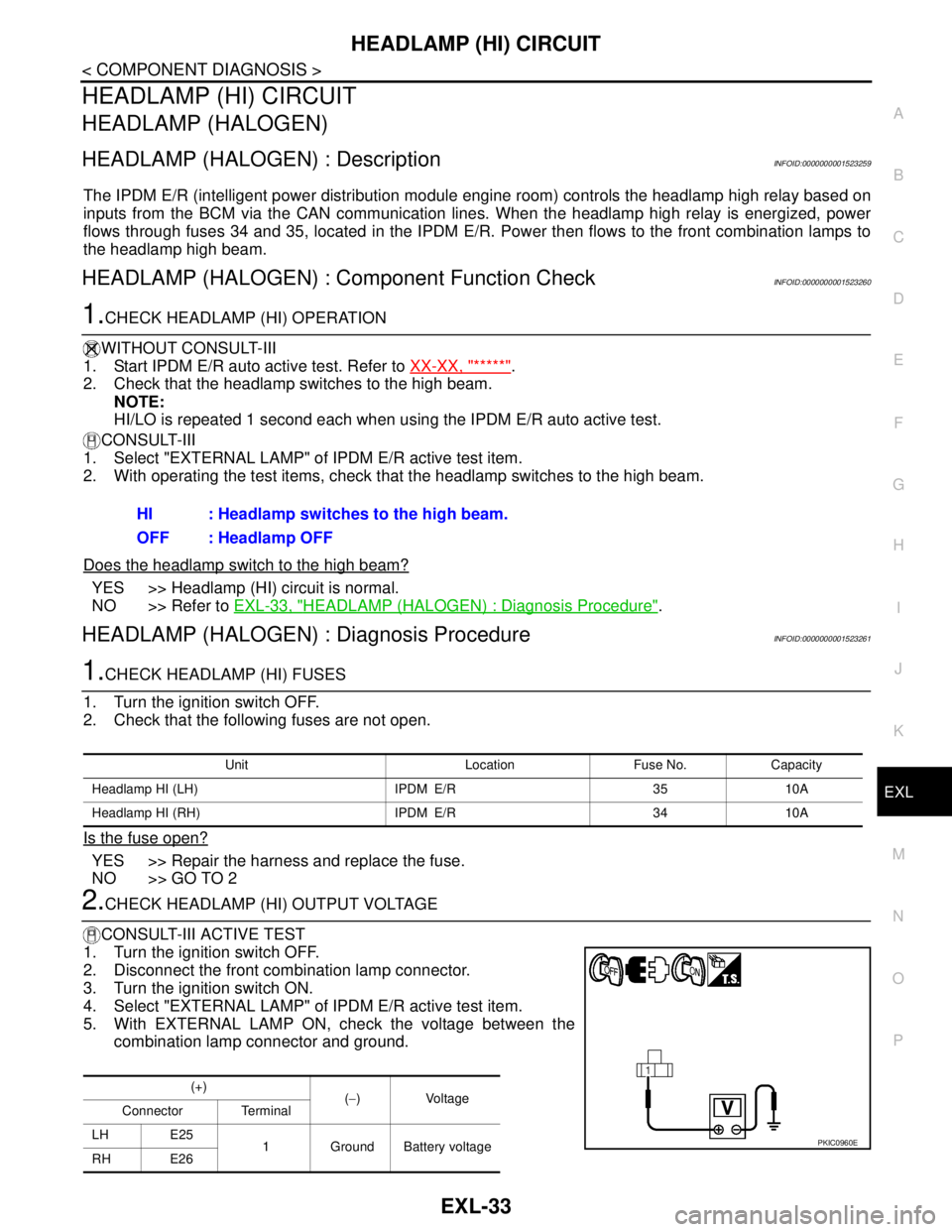
5. With EXTERNAL LAMP ON, check the voltage between the
combination lamp connector and ground.HI : Headlamp switches to the high beam.
OFF : Headlamp OFF
Unit Location Fuse No. Capacity
Headlamp HI (LH) IPDM E/R 35 10A
Headlamp HI (RH) IPDM E/R 34 10A
(+)
(−)Voltage
Connector Terminal
LH E25
1 Ground Battery voltage
RH E26
PKIC0960E
Page 3035 of 5883
EXL-34
< COMPONENT DIAGNOSIS >
HEADLAMP (HI) CIRCUIT
Is the measurement value normal?
YES >> GO TO 4
NO >> GO TO 3
3.CHECK HEADLAMP (HI) CIRCUIT FOR OPEN
1. Turn the ignition switch OFF.
2. Disconnect IPDM E/R connector.
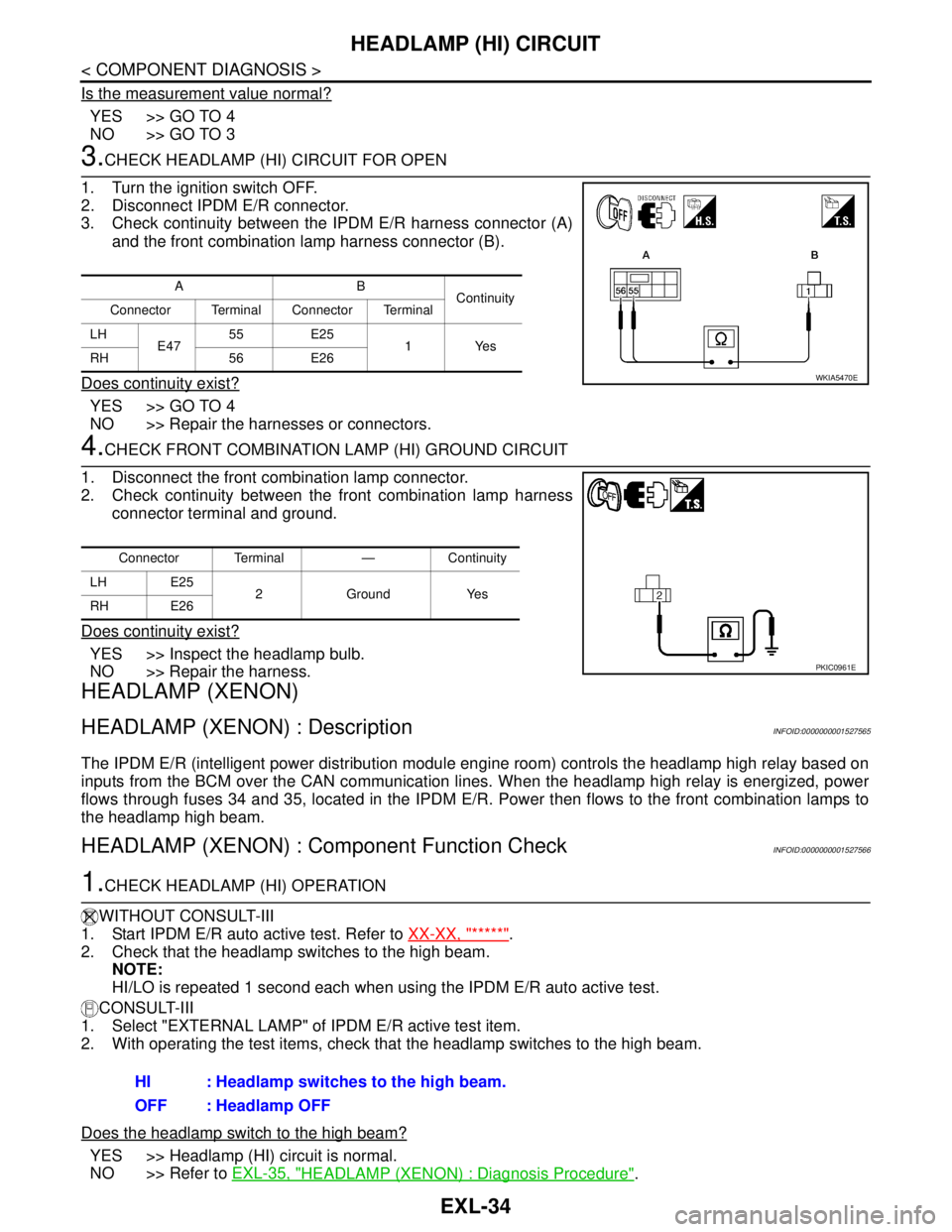
3. Check continuity between the IPDM E/R harness connector (A)
and the front combination lamp harness connector (B).
Does continuity exist?
YES >> GO TO 4
NO >> Repair the harnesses or connectors.
4.CHECK FRONT COMBINATION LAMP (HI) GROUND CIRCUIT
1. Disconnect the front combination lamp connector.
2. Check continuity between the front combination lamp harness
connector terminal and ground.
Does continuity exist?
YES >> Inspect the headlamp bulb.
NO >> Repair the harness.
HEADLAMP (XENON)
HEADLAMP (XENON) : DescriptionINFOID:0000000001527565
The IPDM E/R (intelligent power distribution module engine room) controls the headlamp high relay based on
inputs from the BCM over the CAN communication lines. When the headlamp high relay is energized, power
flows through fuses 34 and 35, located in the IPDM E/R. Power then flows to the front combination lamps to
the headlamp high beam.
HEADLAMP (XENON) : Component Function CheckINFOID:0000000001527566
1.CHECK HEADLAMP (HI) OPERATION
WITHOUT CONSULT-III
1. Start IPDM E/R auto active test. Refer to XX-XX, "*****"
.
2. Check that the headlamp switches to the high beam.
NOTE:
HI/LO is repeated 1 second each when using the IPDM E/R auto active test.
CONSULT-III
1. Select "EXTERNAL LAMP" of IPDM E/R active test item.
2. With operating the test items, check that the headlamp switches to the high beam.
Does the headlamp switch to the high beam?
YES >> Headlamp (HI) circuit is normal.
NO >> Refer to EXL-35, "
HEADLAMP (XENON) : Diagnosis Procedure".
AB
Continuity
Connector Terminal Connector Terminal
LH
E4755 E25
1Yes
RH 56 E26
WKIA5470E
Connector Terminal — Continuity
LH E25
2 Ground Yes
RH E26
PKIC0961E
HI : Headlamp switches to the high beam.
OFF : Headlamp OFF
Page 3036 of 5883
HEADLAMP (HI) CIRCUIT
EXL-35
< COMPONENT DIAGNOSIS >
C
D
E
F
G
H
I
J
K
MA
B
EXL
N
O
P
HEADLAMP (XENON) : Diagnosis ProcedureINFOID:0000000001527567
1.CHECK HEADLAMP (HI) FUSES
1. Turn the ignition switch OFF.
2. Check that the following fuses are not open.
Is the fuse open?
YES >> Repair the harness and replace the fuse.
NO >> GO TO 2
2.CHECK HEADLAMP (HI) OUTPUT VOLTAGE
CONSULT-III ACTIVE TEST
1. Turn the ignition switch OFF.
2. Disconnect the front combination lamp connector.
3. Turn the ignition switch ON.
4. Select "EXTERNAL LAMP" of IPDM E/R active test item.
5. With EXTERNAL LAMP ON, check the voltage between the combination lamp connector and ground.
Is the measurement value normal?
YES >> GO TO 4
NO >> GO TO 3
3.CHECK HEADLAMP (HI) CIRCUIT FOR OPEN
1. Turn the ignition switch OFF.
2. Disconnect IPDM E/R connector.
3. Check continuity between the IPDM E/R harness connector (A) and the front combination lamp harness
connector (B).
Does continuity exist?
YES >> GO TO 4
NO >> Repair the harnesses or connectors.
4.CHECK HEADLAMP (HI) GROUND CIRCUIT
1. Disconnect the front combination lamp connector.
2. Check continuity between the front combination lamp harness connector terminal and ground.
Does continuity exist?
YES >> Inspect the headlamp bulb.
Unit Location Fuse No. Capacity
Headlamp HI (LH) IPDM E/R 35 10A
Headlamp HI (RH) IPDM E/R 34 10A
(+)
(−)Voltage
Connector Terminal
LH E25 4
Ground Battery voltage
RH E26 4
AB
Continuity
Connector Terminal Connector Terminal
LH
E4755 E25 4
Ye s
RH 56 E26 4
Connector Terminal — Continuity
LH E25 1
Ground Yes
RH E26 1
Page 3037 of 5883

EXL-36
< COMPONENT DIAGNOSIS >
HEADLAMP (HI) CIRCUIT
NO >> Repair the harness.
Page 3038 of 5883
HEADLAMP (LO) CIRCUIT
EXL-37
< COMPONENT DIAGNOSIS >
C
D
E
F
G
H
I
J
K
MA
B
EXL
N
O
P
HEADLAMP (LO) CIRCUIT
HEADLAMP (HALOGEN)
HEADLAMP (HALOGEN) : DescriptionINFOID:0000000001523262
The IPDM E/R (intelligent power distribution module engine room) controls the headlamp low relay based on
inputs from the BCM via the CAN communication lines. When the headlamp low relay is energized, power
flows through fuses 40 and 41, located in the IPDM E/R. Power then flows to the front combination lamps to
the headlamp low beam.
HEADLAMP (HALOGEN) : Component Function CheckINFOID:0000000001523263
1.CHECK HEADLAMP (LO) OPERATION
WITHOUT CONSULT-III
1. Start IPDM E/R auto active test. Refer to XX-XX, "*****"
.
2. Check that the headlamp is turned ON.
NOTE:
HI/LO is repeated 1 second each when using the IPDM E/R auto active test.
CONSULT-III
1. Select "EXTERNAL LAMP" of IPDM E/R active test item.
2. With operating the test items, check that the headlamp is turned ON.
Is the headlamp turned ON?
YES >> Headlamp (LO) is normal.
NO >> Refer to EXL-37, "
HEADLAMP (HALOGEN) : Diagnosis Procedure".
HEADLAMP (HALOGEN) : Diagnosis ProcedureINFOID:0000000001523264
1.CHECK HEADLAMP (LO) FUSES
1. Turn the ignition switch OFF.
2. Check that the following fuses are not open.
Is the fuse open?
YES >> Repair the harness and replace the fuse.
NO >> GO TO 2
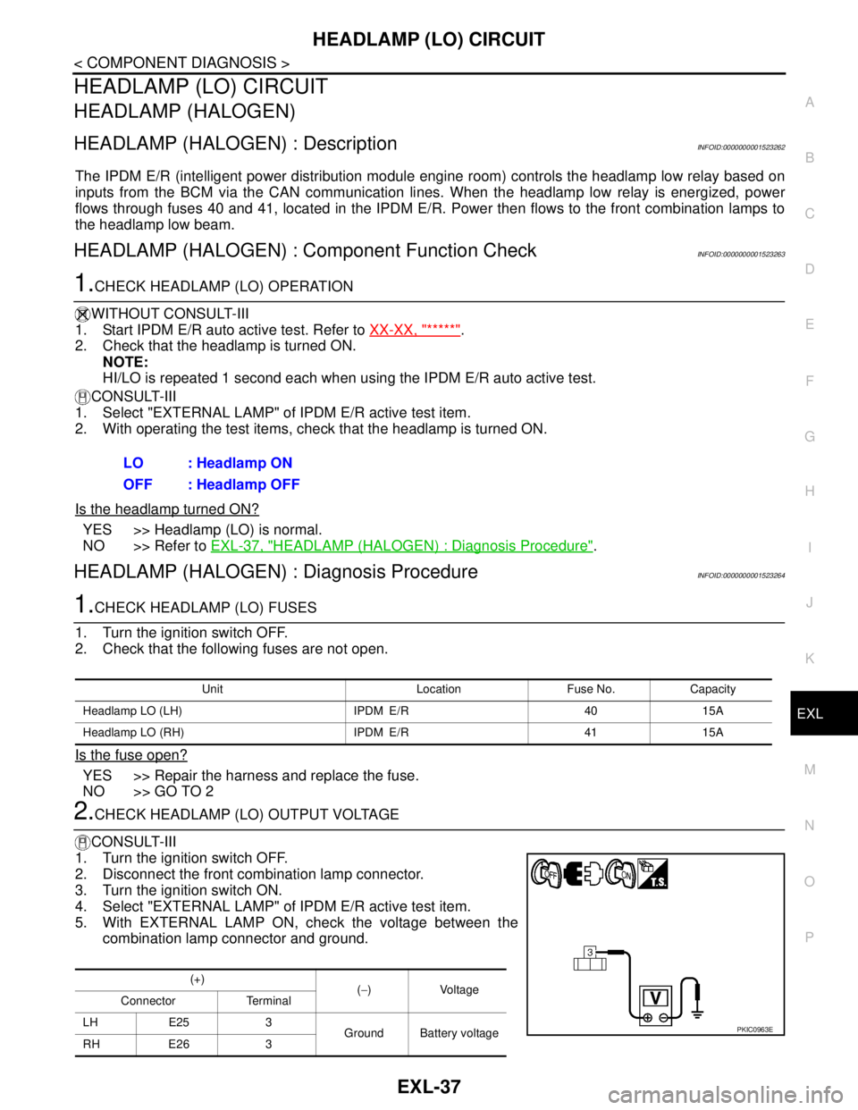
2.CHECK HEADLAMP (LO) OUTPUT VOLTAGE
CONSULT-III
1. Turn the ignition switch OFF.
2. Disconnect the front combination lamp connector.
3. Turn the ignition switch ON.
4. Select "EXTERNAL LAMP" of IPDM E/R active test item.
5. With EXTERNAL LAMP ON, check the voltage between the
combination lamp connector and ground.LO : Headlamp ON
OFF : Headlamp OFF
Unit Location Fuse No. Capacity
Headlamp LO (LH) IPDM E/R 40 15A
Headlamp LO (RH) IPDM E/R 41 15A
(+)
(−)Voltage
Connector Terminal
LH E25 3
Ground Battery voltage
RH E26 3
PKIC0963E
Page 3039 of 5883
EXL-38
< COMPONENT DIAGNOSIS >
HEADLAMP (LO) CIRCUIT
Is the measurement value normal?
YES >> GO TO 4
NO >> GO TO 3
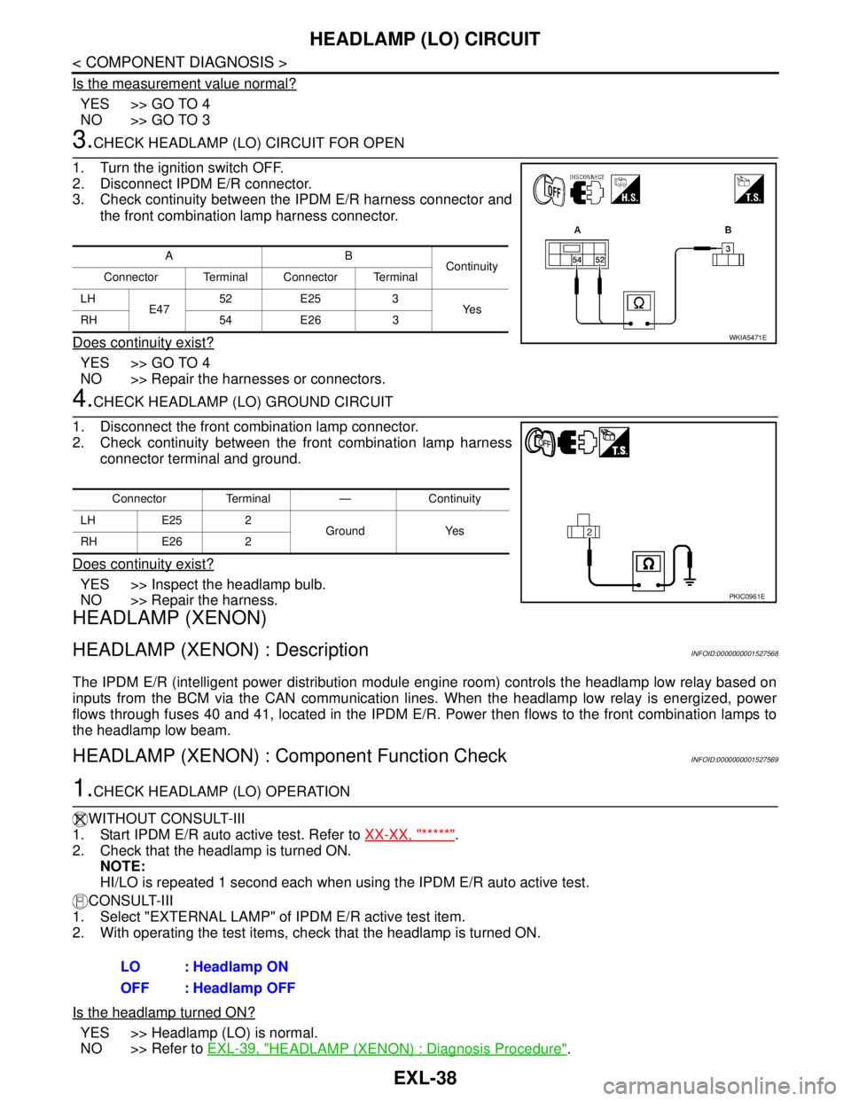
3.CHECK HEADLAMP (LO) CIRCUIT FOR OPEN
1. Turn the ignition switch OFF.
2. Disconnect IPDM E/R connector.
3. Check continuity between the IPDM E/R harness connector and
the front combination lamp harness connector.
Does continuity exist?
YES >> GO TO 4
NO >> Repair the harnesses or connectors.
4.CHECK HEADLAMP (LO) GROUND CIRCUIT
1. Disconnect the front combination lamp connector.
2. Check continuity between the front combination lamp harness
connector terminal and ground.
Does continuity exist?
YES >> Inspect the headlamp bulb.
NO >> Repair the harness.
HEADLAMP (XENON)
HEADLAMP (XENON) : DescriptionINFOID:0000000001527568
The IPDM E/R (intelligent power distribution module engine room) controls the headlamp low relay based on
inputs from the BCM via the CAN communication lines. When the headlamp low relay is energized, power
flows through fuses 40 and 41, located in the IPDM E/R. Power then flows to the front combination lamps to
the headlamp low beam.
HEADLAMP (XENON) : Component Function CheckINFOID:0000000001527569
1.CHECK HEADLAMP (LO) OPERATION
WITHOUT CONSULT-III
1. Start IPDM E/R auto active test. Refer to XX-XX, "*****"
.
2. Check that the headlamp is turned ON.
NOTE:
HI/LO is repeated 1 second each when using the IPDM E/R auto active test.
CONSULT-III
1. Select "EXTERNAL LAMP" of IPDM E/R active test item.
2. With operating the test items, check that the headlamp is turned ON.
Is the headlamp turned ON?
YES >> Headlamp (LO) is normal.
NO >> Refer to EXL-39, "
HEADLAMP (XENON) : Diagnosis Procedure".
AB
Continuity
Connector Terminal Connector Terminal
LH
E4752 E25 3
Ye s
RH 54 E26 3
WKIA5471E
Connector Terminal — Continuity
LH E25 2
Ground Yes
RH E26 2
PKIC0961E
LO : Headlamp ON
OFF : Headlamp OFF
Page 3040 of 5883
HEADLAMP (LO) CIRCUIT
EXL-39
< COMPONENT DIAGNOSIS >
C
D
E
F
G
H
I
J
K
MA
B
EXL
N
O
P
HEADLAMP (XENON) : Diagnosis ProcedureINFOID:0000000001527570
1.CHECK HEADLAMP (LO) FUSES
1. Turn the ignition switch OFF.
2. Check that the following fuses are not open.
Is the fuse open?
YES >> Repair the harness and replace the fuse.
NO >> GO TO 2
2.CHECK HEADLAMP (LO) OUTPUT VOLTAGE
CONSULT-III
1. Turn the ignition switch OFF.
2. Disconnect the front combination lamp connector.
3. Turn the ignition switch ON.
4. Select "EXTERNAL LAMP" of IPDM E/R active test item.
5. With EXTERNAL LAMP ON, check the voltage between the combination lamp connector and ground.
Is the measurement value normal?
YES >> GO TO 4
NO >> GO TO 3
3.CHECK HEADLAMP (LO) CIRCUIT FOR OPEN
1. Turn the ignition switch OFF.
2. Disconnect IPDM E/R connector.
3. Check continuity between the IPDM E/R harness connector and the front combination lamp harness con-
nector.
Does continuity exist?
YES >> GO TO 4
NO >> Repair the harnesses or connectors.
4.CHECK HEADLAMP (LO) GROUND CIRCUIT
1. Disconnect the front combination lamp connector.
2. Check continuity between the front combination lamp harness connector terminal and ground.
Does continuity exist?
YES >> Inspect the headlamp bulb.
Unit Location Fuse No. Capacity
Headlamp LO (LH) IPDM E/R 40 15A
Headlamp LO (RH) IPDM E/R 41 15A
(+)
(−)Voltage
Connector Terminal
LH E25 3
Ground Battery voltage
RH E26 3
AB
Continuity
Connector Terminal Connector Terminal
LH
E4752 E25 3
Ye s
RH 54 E26 3
Connector Terminal — Continuity
LH E25 1
Ground Yes
RH E26 1