NISSAN TIIDA 2007 Service Repair Manual
Manufacturer: NISSAN, Model Year: 2007, Model line: TIIDA, Model: NISSAN TIIDA 2007Pages: 5883, PDF Size: 78.95 MB
Page 3021 of 5883

EXL-20
< FUNCTION DIAGNOSIS >
FRONT FOG LAMP
Component Description
INFOID:0000000001523240
Part Description
BCM Monitors the combination switch position.
Requests the IPDM E/R (via CAN communication lines) to actuate the front fog lamp
relay.
Requests the combination meter (via CAN communication lines) to turn the front fog
lamp indicator lamp ON.
IPDM E/RControls the integrated front fog lamp relay based on input from the BCM via the CAN
communication lines.
Combination switch
(Lighting & turn signal switch)Refer to BCS-9, "
System Description".
Combination meter
(front fog lamp indicator lamp)Controls the front fog lamp indicator during front fog lamp operation based on input
from the BCM via the CAN communication lines.
Page 3022 of 5883
REAR FOG LAMP
EXL-21
< FUNCTION DIAGNOSIS >
C
D
E
F
G
H
I
J
K
MA
B
EXL
N
O
P
REAR FOG LAMP
System DiagramINFOID:0000000001527666
System DescriptionINFOID:0000000001527667
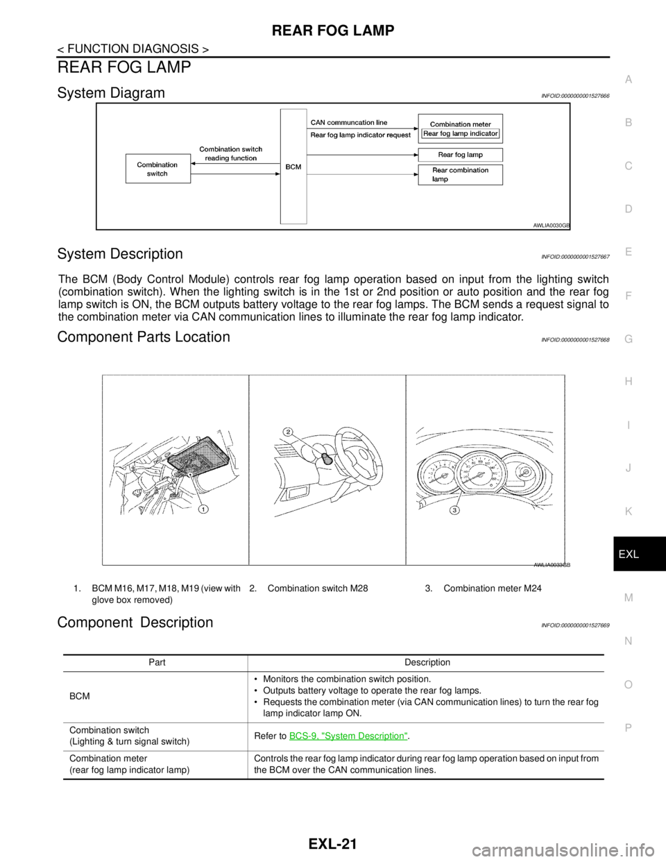
The BCM (Body Control Module) controls rear fog lamp operation based on input from the lighting switch
(combination switch). When the lighting switch is in the 1st or 2nd position or auto position and the rear fog
lamp switch is ON, the BCM outputs battery voltage to the rear fog lamps. The BCM sends a request signal to
the combination meter via CAN communication lines to illuminate the rear fog lamp indicator.
Component Parts LocationINFOID:0000000001527668
Component DescriptionINFOID:0000000001527669
AWLIA0030GB
1. BCM M16, M17, M18, M19 (view with
glove box removed)2. Combination switch M28 3. Combination meter M24
AWLIA0033GB
Part Description
BCM Monitors the combination switch position.
Outputs battery voltage to operate the rear fog lamps.
Requests the combination meter (via CAN communication lines) to turn the rear fog
lamp indicator lamp ON.
Combination switch
(Lighting & turn signal switch)Refer to BCS-9, "
System Description".
Combination meter
(rear fog lamp indicator lamp)Controls the rear fog lamp indicator during rear fog lamp operation based on input from
the BCM over the CAN communication lines.
Page 3023 of 5883
EXL-22
< FUNCTION DIAGNOSIS >
TURN SIGNAL AND HAZARD WARNING LAMPS
TURN SIGNAL AND HAZARD WARNING LAMPS
System DiagramINFOID:0000000001523241
System DescriptionINFOID:0000000001523242
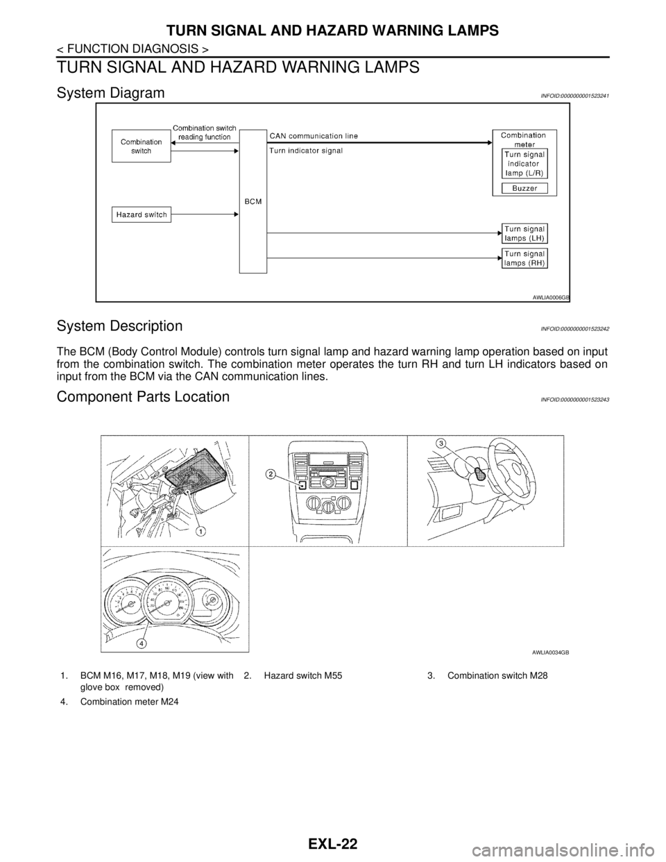
The BCM (Body Control Module) controls turn signal lamp and hazard warning lamp operation based on input
from the combination switch. The combination meter operates the turn RH and turn LH indicators based on
input from the BCM via the CAN communication lines.
Component Parts LocationINFOID:0000000001523243
AWLIA0006GB
1. BCM M16, M17, M18, M19 (view with
glove box removed)2. Hazard switch M55 3. Combination switch M28
4. Combination meter M24
AWLIA0034GB
Page 3024 of 5883
TURN SIGNAL AND HAZARD WARNING LAMPS
EXL-23
< FUNCTION DIAGNOSIS >
C
D
E
F
G
H
I
J
K
MA
B
EXL
N
O
P
Component DescriptionINFOID:0000000001523244
Part Description
BCM Monitors the combination switch position.
Monitors hazard switch position.
Controls flasher output to the front, side and rear turn signals based on inputs from
the combination and hazard switches.
Requests the combination meter (via CAN communication lines) to turn the turn RH
and turn LH indicator lamps ON.
Combination switch
(Lighting & turn signal switch)Refer to BCS-9, "
System Description".
Combination meter
(turn LH and turn RH indicator lamp)Controls the front fog lamp indicator during front fog lamp operation based on input
from the BCM via the CAN communication lines.
Page 3025 of 5883
EXL-24
< FUNCTION DIAGNOSIS >
PARKING, LICENSE PLATE AND TAIL LAMPS
PARKING, LICENSE PLATE AND TAIL LAMPS
System DiagramINFOID:0000000001523245
WITHOUT DAYTIME LIGHT SYSTEM
WITH DAYTIME LIGHT SYSTEM
System DescriptionINFOID:0000000001523246
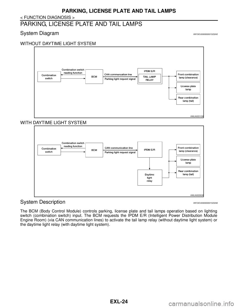
The BCM (Body Control Module) controls parking, license plate and tail lamps operation based on lighting
switch (combination switch) input. The BCM requests the IPDM E/R (Intelligent Power Distribution Module
Engine Room) (via CAN communication lines) to activate the tail lamp relay (without daytime light system) or
the daytime light relay (with daytime light system).
AWLIA0031GB
AWLIA0035GB
Page 3026 of 5883
PARKING, LICENSE PLATE AND TAIL LAMPS
EXL-25
< FUNCTION DIAGNOSIS >
C
D
E
F
G
H
I
J
K
MA
B
EXL
N
O
P
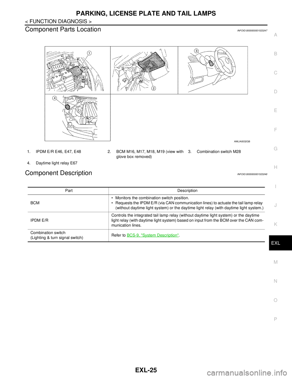
Component Parts LocationINFOID:0000000001523247
Component DescriptionINFOID:0000000001523248
1. IPDM E/R E46, E47, E48 2. BCM M16, M17, M18, M19 (view with
glove box removed)3. Combination switch M28
4. Daytime light relay E67
AWLIA0032GB
Part Description
BCM Monitors the combination switch position.
Requests the IPDM E/R (via CAN communication lines) to actuate the tail lamp relay
(without daytime light system) or the daytime light relay (with daytime light system.)
IPDM E/RControls the integrated tail lamp relay (without daytime light system) or the daytime
light relay (with daytime light system) based on input from the BCM over the CAN com-
munication lines.
Combination switch
(Lighting & turn signal switch)Refer to BCS-9, "
System Description".
Page 3027 of 5883

EXL-26
< FUNCTION DIAGNOSIS >
DIAGNOSIS SYSTEM (BCM)
DIAGNOSIS SYSTEM (BCM)
COMMON ITEM
COMMON ITEM : CONSULT-III Function (BCM - COMMON ITEM)INFOID:0000000001528970
APPLICATION ITEM
CONSULT-III performs the following functions via CAN communication with BCM.
BCM
BCM : CONSULT-III Function (BCM - BCM)INFOID:0000000001528971
WORK SUPPORT
HEADLAMP
HEADLAMP : CONSULT-III Function (BCM - HEAD LAMP)INFOID:0000000001528977
WORK SUPPORT
*: Initial setting
DATA MONITOR
Diagnosis mode Function Description
WORK SUPPORT Changes the setting for each system function.
SELF-DIAG RESULTS Displays the diagnosis results judged by BCM. Refer to BCS-54, "
DTCIndex".
CAN DIAG SUPPORT MNTR Monitors the reception status of CAN communication viewed from BCM.
DATA MONITOR The BCM input/output signals are displayed.
ACTIVE TEST The signals used to activate each device are forcibly supplied from BCM.
ECU IDENTIFICATION The BCM part number is displayed.
CONFIGURATION Enables to read and save the vehicle specification.
Enables to write the vehicle specification when replacing BCM.
Item Description
RESET SETTING VALUE Return a value set with WORK SUPPORT of each system to a default value in factory shipment.
Work item Setting Description
BATTERY SAVER SETON*
Battery saver mode can be changed.
OFF
Monitor item
[Unit]Description
IGN ON SW [ON/OFF] Ignition switch (ON) status judged from IGN signal (ignition power supply)
HI BEAM SW [ON/OFF]
Each switch status that BCM judges from the combination switch reading function H/L SW POS [ON/OFF]
LIGHT SW 1ST [ON/OFF]
PASSING SW [ON/OFF]
AUTO LIGHT SW [ON/OFF]
FR FOG SW [ON/OFF]
RR FOG SW [ON/OFF]
DOOR SW-DR [ON/OFF] The switch status input from front door switch (driver side)
ENGINE STATUS The engine status received from ECM with CAN communication
Page 3028 of 5883

DIAGNOSIS SYSTEM (BCM)
EXL-27
< FUNCTION DIAGNOSIS >
C
D
E
F
G
H
I
J
K
MA
B
EXL
N
O
P
ACTIVE TEST
FLASHER
FLASHER : CONSULT-III Function (BCM - FLASHER)INFOID:0000000001528979
WORK SUPPORT
DATA MONITOR
ACTIVE TEST
LIT-SEN FAIL [OK/NOTOK] The sensor status received from light & rain sensor with serial link
The serial link condition that BCM judges
AUT LIGHT SYS [ON/OFF] Auto light system status that BCM judges from the vehicle conditionMonitor item
[Unit]Description
Test item Operation Description
TAIL LAMPONTransmits the position light request signal to IPDM E/R with CAN com-
munication to turn the tail lamp ON.
OFF Stops the tail lamp request signal transmission.
HEAD LAMPHITransmits the high beam request signal with CAN communication to turn
the headlamp (HI).
LOTransmits the low beam request signal with CAN communication to turn
the headlamp (LO).
OFF Stops the high & low beam request signal transmission.
FR FOG LAMPONTransmits the front fog lights request signal to IPDM E/R with CAN com-
munication to turn the front fog lamp ON.
OFF Stops the front fog lights request signal transmission.
RR FOG LAMPON Outputs the voltage to turn the rear fog lamp ON.
Transmits the rear fog lamp status signal to the combination meter with
CAN communication to turn the rear fog lamp indicator lamp ON.
OFF Stops the voltage to turn the rear fog lamp OFF.
Stops the rear fog lamp status signal transmission.
DAYTIME RUNNING LIGHTONTransmits the day time running light request signal to IPDM E/R with
CAN communication to turn the each lamps ON.
OFF Stops the day time running light request signal transmission.
Work Item Description
HAZARD LAMP SETOperation MODE1 MODE2 MODE3
MODE4
Keyfob operation Lock Unlock Lock Unlock Lock Unlock Lock Unlock
Hazard lamp flash - - - Twice Once - Once Twice
Monitor Item
[Unit]Description
IGN ON SW [ON/OFF] Ignition switch (ON) status judged from IGN signal (ignition power supply)
HAZARD SW [ON/OFF] The switch status input from the hazard switch
TURN SIGNAL R [ON/OFF]
Each switch condition that BCM judges from the combination switch reading function
TURN SIGNAL L [ON/OFF]
TURN/L MNTR [ON/OFF] Displays status (one bulb out: ON/other: OFF) as judged from bulb signal
Page 3029 of 5883

EXL-28
< FUNCTION DIAGNOSIS >
DIAGNOSIS SYSTEM (BCM)
COMB SW
COMB SW : CONSULT-III Function (BCM - COMB SW)INFOID:0000000001528982
DATA MONITOR
BATTERY SAVER
BATTERY SAVER : CONSULT-III Function (BCM - BATTERY SAVER)INFOID:0000000001528984
WORK SUPPORT
Test Item Operation Description
FLASHERRH Outputs the voltage to turn the right side turn signal lamps ON.
LH Outputs the voltage to turn the left side turn signal lamps ON.
OFF Stops the voltage to turn the turn signal lamps OFF.
Monitor Item
[Unit]Description
TURN SIGNAL R
[OFF/ON]Displays the status of the TURN RH switch in combination switch judged by BCM with the combination switch
reading function.
TURN SIGNAL L
[OFF/ON]Displays the status of the TURN LH switch in combination switch judged by BCM with the combination switch
reading function.
HI BEAM SW
[OFF/ON]Displays the status of the HI BEAM switch in combination switch judged by BCM with the combination switch
reading function.
H/L SW POS
[OFF/ON]Displays the status of the HEADLAMP switch in combination switch judged by BCM with the combination
switch reading function.
LIGHT SW 1ST
[OFF/ON]Displays the status of the HEADLAMP switch in combination switch judged by BCM with the combination
switch reading function.
PASSING SW
[OFF/ON]Displays the status of the PASSING switch in combination switch judged by BCM with the combination switch
reading function.
AUTO LIGHT SW
[OFF/ON]Displays the status of the AUTO LIGHT switch in combination switch judged by BCM with the combination
switch reading function.
FR FOG SW
[OFF/ON]Displays the status of the FR FOG switch in combination switch judged by BCM with the combination switch
reading function.
RR FOG SW
[OFF/ON]Displays the status of the RR FOG switch in combination switch judged by BCM with the combination switch
reading function.
FR WIPER HI
[OFF/ON]Displays the status of the FR WIPER HI switch in combination switch judged by BCM with the combination
switch reading function.
FR WIPER LOW
[OFF/ON]Displays the status of the FR WIPER LOW switch in combination switch judged by BCM with the combination
switch reading function.
FR WIPER INT
[OFF/ON]Displays the status of the FR WIPER INT switch in combination switch judged by BCM with the combination
switch reading function.
FR WASHER SW
[OFF/ON]Displays the status of the FR WASHER switch in combination switch judged by BCM with the combination
switch reading function.
INT VOLUME
[1 - 7]Displays the status of wiper intermittent dial position judged by BCM with the combination switch reading
function.
RR WIPER ON
[OFF/ON]Displays the status of the RR WIPER switch in combination switch judged by BCM with the combination
switch reading function.
RR WIPER INT
[OFF/ON]Displays the status of the RR WIPER INT switch in combination switch judged by BCM with the combination
switch reading function.
RR WASHER SW
[OFF/ON]Displays the status of the RR WASHER switch in combination switch judged by BCM with the combination
switch reading function.
Page 3030 of 5883

DIAGNOSIS SYSTEM (BCM)
EXL-29
< FUNCTION DIAGNOSIS >
C
D
E
F
G
H
I
J
K
MA
B
EXL
N
O
P
*: Initial setting
DATA MONITOR
1: With remote keyless entry
2: With Intelligent Key
ACTIVE TEST
*: Each lamp switch is in ON position.Work Item Setting Item Setting
ROOM LAMP TIMER SETMODE 1* 15 min.
Sets the interior room lamp battery saver timer operating
time.
MODE 2 30 min.
Monitor Item
[Unit]Description
IGN ON SW [ON/OFF] Ignition switch (ON) status judges from IGN signal (ignition power supply)
KEY SW
1 [ON/OFF]The switch status input from key switch
PUSH SW
2 [ON/OFF]Push switch status received from Intelligent Key unit by CAN communication
DOOR SW-DR [ON/OFF] The switch status input from front door switch (driver side)
DOOR SW-AS [ON/OFF] The switch status input from front door switch (passenger side)
DOOR SW-RR [ON/OFF] The switch status input from rear door switch RH
DOOR SW- RL [ON/OFF] The switch status input from rear door switch LH
BACK DOOR SW [ON/OFF] The switch status input from back door switch
CDL LOCK SW [ON/OFF] Lock switch status input from door lock and unlock switch
CDL UNLOCK SW [ON/OFF] Unlock switch status input from door lock and unlock switch
I-KEY LOCK
2 [ON/OFF]Lock signal status received from Intelligent Key unit by CAN communication
I-KEY UNLOCK
2 [ON/OFF]Unlock signal status received from Intelligent Key unit by CAN communication
KEYLESS LOCK
1 [ON/OFF]Lock signal status received from remote keyless entry receiver (integrated in the
BCM)
KEYLESS UNLOCK
1 [ON/OFF]Unlock signal status received from remote keyless entry receiver (integrated in the
BCM)
Test item Operation Description
BATTERY SAVEROFF Cuts the interior room lamp power supply to turn interior room lamps OFF.
ON Outputs the interior room lamp power supply to turn interior room lamps ON.*