NISSAN TIIDA 2007 Service Repair Manual
Manufacturer: NISSAN, Model Year: 2007, Model line: TIIDA, Model: NISSAN TIIDA 2007Pages: 5883, PDF Size: 78.95 MB
Page 4411 of 5883

PARKING BRAKE SHOE
PB-7
< REMOVAL AND INSTALLATION >
C
D
E
G
H
I
J
K
L
MA
B
PB
N
O
P
PARKING BRAKE SHOE
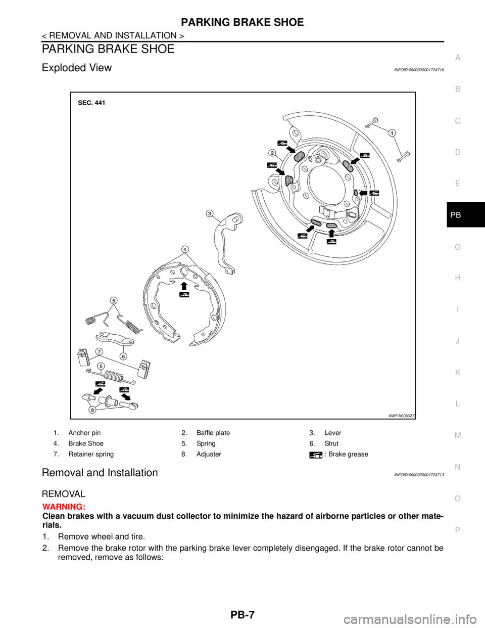
Exploded ViewINFOID:0000000001724716
Removal and InstallationINFOID:0000000001724713
REMOVAL
WARNING:
Clean brakes with a vacuum dust collector to minimize the hazard of airborne particles or other mate-
rials.
1. Remove wheel and tire.
2. Remove the brake rotor with the parking brake lever completely disengaged. If the brake rotor cannot be
removed, remove as follows:
1. Anchor pin 2. Baffle plate 3. Lever
4. Brake Shoe 5. Spring 6. Strut
7. Retainer spring 8. Adjuster : Brake grease
AWFIA0083ZZ
Page 4412 of 5883

PB-8
< REMOVAL AND INSTALLATION >
PARKING BRAKE SHOE
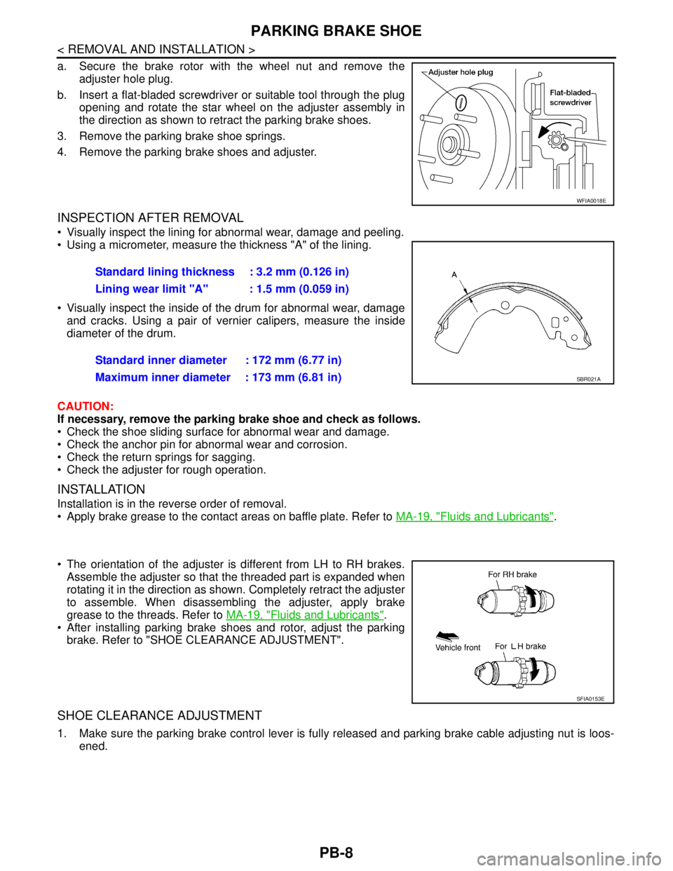
a. Secure the brake rotor with the wheel nut and remove the
adjuster hole plug.
b. Insert a flat-bladed screwdriver or suitable tool through the plug
opening and rotate the star wheel on the adjuster assembly in
the direction as shown to retract the parking brake shoes.
3. Remove the parking brake shoe springs.
4. Remove the parking brake shoes and adjuster.
INSPECTION AFTER REMOVAL
Visually inspect the lining for abnormal wear, damage and peeling.
Using a micrometer, measure the thickness "A" of the lining.
Visually inspect the inside of the drum for abnormal wear, damage
and cracks. Using a pair of vernier calipers, measure the inside
diameter of the drum.
CAUTION:
If necessary, remove the parking brake shoe and check as follows.
Check the shoe sliding surface for abnormal wear and damage.
Check the anchor pin for abnormal wear and corrosion.
Check the return springs for sagging.
Check the adjuster for rough operation.
INSTALLATION
Installation is in the reverse order of removal.
Apply brake grease to the contact areas on baffle plate. Refer to MA-19, "
Fluids and Lubricants".
The orientation of the adjuster is different from LH to RH brakes.
Assemble the adjuster so that the threaded part is expanded when
rotating it in the direction as shown. Completely retract the adjuster
to assemble. When disassembling the adjuster, apply brake
grease to the threads. Refer to MA-19, "
Fluids and Lubricants".
After installing parking brake shoes and rotor, adjust the parking
brake. Refer to "SHOE CLEARANCE ADJUSTMENT".
SHOE CLEARANCE ADJUSTMENT
1. Make sure the parking brake control lever is fully released and parking brake cable adjusting nut is loos-
ened.
WFIA0018E
Standard lining thickness : 3.2 mm (0.126 in)
Lining wear limit "A" : 1.5 mm (0.059 in)
Standard inner diameter : 172 mm (6.77 in)
Maximum inner diameter : 173 mm (6.81 in)
SBR021A
SFIA0153E
Page 4413 of 5883

PARKING BRAKE SHOE
PB-9
< REMOVAL AND INSTALLATION >
C
D
E
G
H
I
J
K
L
MA
B
PB
N
O
P
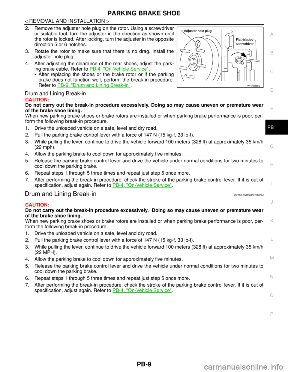
2. Remove the adjuster hole plug on the rotor. Using a screwdriver
or suitable tool, turn the adjuster in the direction as shown until
the rotor is locked. After locking, turn the adjuster in the opposite
direction 5 or 6 notches.
3. Rotate the rotor to make sure that there is no drag. Install the
adjuster hole plug.
4. After adjusting the clearance of the rear shoes, adjust the park-
ing brake cable. Refer to PB-4, "
On-Vehicle Service".
After replacing the shoes or the brake rotor or if the parking
brake does not function well, perform the break-in procedure.
Refer to PB-9, "
Drum and Lining Break-in".
Drum and Lining Break-in
CAUTION:
Do not carry out the break-in procedure excessively. Doing so may cause uneven or premature wear
of the brake shoe lining.
When new parking brake shoes or brake rotors are installed or when parking brake performance is poor, per-
form the following break-in procedure.
1. Drive the unloaded vehicle on a safe, level and dry road.
2. Pull the parking brake control lever with a force of 147 N (15 kg-f, 33 lb-f).
3. While pulling the lever, continue to drive the vehicle forward 100 meters (328 ft) at approximately 35 km/h
(22 mph).
4. Allow the parking brake to cool down for approximately five minutes.
5. Release the parking brake control lever and drive the vehicle under normal conditions for two minutes to
cool down the parking brake.
6. Repeat steps 1 through 5 three times and repeat just step 5 once more.
7. After performing the break-in procedure, check the stroke of the parking brake control lever. If it is out of
specification, adjust again. Refer to PB-4, "
On-Vehicle Service".
Drum and Lining Break-inINFOID:0000000001724714
CAUTION:
Do not carry out the break-in procedure excessively. Doing so may cause uneven or premature wear
of the brake shoe lining.
When new parking brake shoes or brake rotors are installed or when parking brake performance is poor, per-
form the following break-in procedure.
1. Drive the unloaded vehicle on a safe, level and dry road.
2. Pull the parking brake control lever with a force of 147 N (15 kg-f, 33 lb-f).
3. While pulling the lever, continue to drive the vehicle forward 100 meters (328 ft) at approximately 35 km/h
(22 MPH).
4. Allow the parking brake to cool down for approximately five minutes.
5. Release the parking brake control lever and drive the vehicle under normal conditions for two minutes to
cool down the parking brake.
6. Repeat steps 1 through 5 three times and repeat just step 5 once more.
7. After performing the break-in procedure, check the stroke of the parking brake control lever. If it is out of
specification, adjust again. Refer to PB-4, "
On-Vehicle Service".
WFIA0286E
Page 4414 of 5883

PB-10
< SERVICE DATA AND SPECIFICATIONS (SDS)
SERVICE DATA AND SPECIFICATIONS (SDS)
SERVICE DATA AND SPECIFICATIONS (SDS)
SERVICE DATA AND SPECIFICATIONS (SDS)
Parking Brake ControlINFOID:0000000001716780
Parking Drum BrakeINFOID:0000000001724715
Control typeHand lever
Number of notches [under a force of 196 N (20 kg-f, 44lb-f)] 8 −9
Number of notches when warning lamp switch comes on 1
Brake liningStandard thickness (new) 3.2 mm (0.126 in)
Wear limit thickness 1.5 mm (0.059 in)
Drum (disc)Standard inner diameter (new) 172 mm (6.77 in)
Wear limit of inner diameter 173 mm (6.81 in)
Page 4415 of 5883

PCS
PCS-1
ELECTRICAL & POWER CONTROL
C
D
E
F
G
H
I
J
K
L B
SECTION PCS
A
O
P N
CONTENTS
POWER CONTROL SYSTEM
IPDM E/R
FUNCTION DIAGNOSIS ...............................
3
RELAY CONTROL SYSTEM ..............................3
System Diagram ........................................................3
System Description ...................................................4
Component Parts Location ........................................5
POWER CONTROL SYSTEM .............................6
System Diagram ........................................................6
System Description ...................................................6
SIGNAL BUFFER SYSTEM ................................7
System Diagram ........................................................7
System Description ...................................................7
POWER CONSUMPTION CONTROL SYS-
TEM .....................................................................
8
System Diagram ........................................................8
System Description ...................................................8
Component Parts Location ........................................9
DIAGNOSIS SYSTEM (IPDM E/R) .....................10
Diagnosis Description .............................................10
CONSULT - III Function (IPDM E/R) .......................13
COMPONENT DIAGNOSIS .........................15
U1000 CAN COMM CIRCUIT .............................15
Description ..............................................................15
DTC Logic ...............................................................15
Diagnosis Procedure ...............................................15
POWER SUPPLY AND GROUND CIRCUIT ......16
Diagnosis Procedure ...............................................16
ECU DIAGNOSIS .........................................17
IPDM E/R (INTELLIGENT POWER DISTRI-
BUTION MODULE ENGINE ROOM) .................
17
Reference Value .....................................................17
Terminal Layout ......................................................19
Physical Values .......................................................19
Wiring Diagram ........................................................23
Fail Safe ..................................................................26
DTC Index ...............................................................28
PRECAUTION ..............................................29
PRECAUTIONS .................................................29
Precaution for Supplemental Restraint System
(SRS) "AIR BAG" and "SEAT BELT PRE-TEN-
SIONER" .................................................................
29
REMOVAL AND INSTALLATION ...............30
IPDM E/R (INTELLIGENT POWER DISTRI-
BUTION MODULE ENGINE ROOM) ................
30
Removal and Installation of IPDM E/R ....................30
POWER DISTRIBUTION SYSTEM
BASIC INSPECTION ...................................
31
DIAGNOSIS AND REPAIR WORKFLOW ........31
Work Flow ................................................................31
FUNCTION DIAGNOSIS ..............................34
POWER DISTRIBUTION SYSTEM ...................34
System Description ..................................................34
Component Parts Location ......................................34
Component Description ..........................................34
DIAGNOSIS SYSTEM (BCM) ...........................35
COMMON ITEM .........................................................35
COMMON ITEM : Diagnosis Description ................35
COMMON ITEM : CONSULT-III Function ...............35
INTELLIGENT KEY ....................................................35
INTELLIGENT KEY : CONSULT-III Function
(BCM - INTELLIGENT KEY) ....................................
35
COMPONENT DIAGNOSIS .........................36
Page 4416 of 5883

PCS-2
U1000 CAN COMM CIRCUIT ............................36
Description ..............................................................36
DTC Logic ...............................................................36
Diagnosis Procedure ..............................................36
POWER SUPPLY AND GROUND CIRCUIT .....37
BCM ...........................................................................37
BCM : Diagnosis Procedure ...................................37
BCM : Special Repair Requirement ........................37
IPDM E/R (INTELLIGENT POWER DISTRIBU-
TION MODULE ENGINE ROOM) .............................
37
IPDM E/R (INTELLIGENT POWER DISTRIBU-
TION MODULE ENGINE ROOM) : Diagnosis Pro-
cedure .....................................................................
37
ECU DIAGNOSIS ........................................38
BCM (BODY CONTROL MODULE) ..................38
Reference Value .....................................................38
Terminal Layout ......................................................38
Physical Values ......................................................38
Wiring Diagram .......................................................38
DTC Inspection Priority Chart ...............................38
DTC Index ..............................................................38
IPDM E/R (INTELLIGENT POWER DISTRI-
BUTION MODULE ENGINE ROOM) .................
39
Reference Value .....................................................39
Terminal Layout ......................................................39
Physical Values .......................................................39
Wiring Diagram .......................................................39
Fail Safe .................................................................39
DTC Index ..............................................................39
ON-VEHICLE MAINTENANCE ..................40
PRE-INSPECTION FOR DIAGNOSTIC ............40
Basic Inspection ......................................................40
ON-VEHICLE REPAIR ...............................41
BCM (BODY CONTROL MODULE) ..................41
Removal and Installation .........................................41
Page 4417 of 5883
![NISSAN TIIDA 2007 Service Repair Manual PCS
RELAY CONTROL SYSTEM
PCS-3
< FUNCTION DIAGNOSIS >[IPDM E/R]
C
D
E
F
G
H
I
J
K
L B A
O
P N
FUNCTION DIAGNOSIS
RELAY CONTROL SYSTEM
System DiagramINFOID:0000000001697579
AWMIA0020GB NISSAN TIIDA 2007 Service Repair Manual PCS
RELAY CONTROL SYSTEM
PCS-3
< FUNCTION DIAGNOSIS >[IPDM E/R]
C
D
E
F
G
H
I
J
K
L B A
O
P N
FUNCTION DIAGNOSIS
RELAY CONTROL SYSTEM
System DiagramINFOID:0000000001697579
AWMIA0020GB](/img/5/57395/w960_57395-4416.png)
PCS
RELAY CONTROL SYSTEM
PCS-3
< FUNCTION DIAGNOSIS >[IPDM E/R]
C
D
E
F
G
H
I
J
K
L B A
O
P N
FUNCTION DIAGNOSIS
RELAY CONTROL SYSTEM
System DiagramINFOID:0000000001697579
AWMIA0020GB
Page 4418 of 5883
![NISSAN TIIDA 2007 Service Repair Manual PCS-4
< FUNCTION DIAGNOSIS >[IPDM E/R]
RELAY CONTROL SYSTEM
System Description
INFOID:0000000001697580
IPDM E/R activates the internal control circuit to perform the relay ON-OFF control according to NISSAN TIIDA 2007 Service Repair Manual PCS-4
< FUNCTION DIAGNOSIS >[IPDM E/R]
RELAY CONTROL SYSTEM
System Description
INFOID:0000000001697580
IPDM E/R activates the internal control circuit to perform the relay ON-OFF control according to](/img/5/57395/w960_57395-4417.png)
PCS-4
< FUNCTION DIAGNOSIS >[IPDM E/R]
RELAY CONTROL SYSTEM
System Description
INFOID:0000000001697580
IPDM E/R activates the internal control circuit to perform the relay ON-OFF control according to the input sig-
nals from various sensors and the request signals received from control units via CAN communication.
CAUTION:
IPDM E/R integrated relays cannot be removed.
Control relay Input/output Transmit unit Control partReference
page
Front fog lamp relay Front fog lamp request signal BCM (CAN) Front fog lampsEXL-19
• Headlamp high relay
Headlamp low relay High beam request signal
Low beam request signalBCM (CAN) Headlamp high
Headlamp lowEXL-8
EXL-10
Tail lamp relay Position light request signal BCM (CAN)Parking lamps
License plate lamps
Tail lamps
Illumination systemEXL-24
Front wiper relay
Front wiper high relayFront wiper request signal BCM (CAN) Front wiper motorWW-4
Rear window defogger re-
layRear window defogger re-
quest signalBCM (CAN) Rear window defoggerDEF-6
A/C relay A/C request signalBCM (CAN)
ECM (CAN)A/C compressorHAC-11
Starter relay Ignition switch START signal TCM Starter motorSTR-6
Cooling fan relay Cooling fan request signal ECM (CAN) Cooling fan relayCO-4
ECM relay ECM relay control signal ECM (CAN) ECM relayEC-124
Throttle control motor relayThrottle control motor control
signalECM (CAN)Throttle control motor re-
layEC-38
Fuel pump relay Fuel pump request signal ECM (CAN) Fuel pumpEC-38
Ignition relay Ignition switch ON signal Ignition switch Ignition relayEC-47
Page 4419 of 5883
![NISSAN TIIDA 2007 Service Repair Manual PCS
RELAY CONTROL SYSTEM
PCS-5
< FUNCTION DIAGNOSIS >[IPDM E/R]
C
D
E
F
G
H
I
J
K
L B A
O
P N
Component Parts LocationINFOID:0000000001697581
1. IPDM E/R E42, E43, E44, E45, E46,
E47, E48
ALMIA0313ZZ NISSAN TIIDA 2007 Service Repair Manual PCS
RELAY CONTROL SYSTEM
PCS-5
< FUNCTION DIAGNOSIS >[IPDM E/R]
C
D
E
F
G
H
I
J
K
L B A
O
P N
Component Parts LocationINFOID:0000000001697581
1. IPDM E/R E42, E43, E44, E45, E46,
E47, E48
ALMIA0313ZZ](/img/5/57395/w960_57395-4418.png)
PCS
RELAY CONTROL SYSTEM
PCS-5
< FUNCTION DIAGNOSIS >[IPDM E/R]
C
D
E
F
G
H
I
J
K
L B A
O
P N
Component Parts LocationINFOID:0000000001697581
1. IPDM E/R E42, E43, E44, E45, E46,
E47, E48
ALMIA0313ZZ
Page 4420 of 5883
![NISSAN TIIDA 2007 Service Repair Manual PCS-6
< FUNCTION DIAGNOSIS >[IPDM E/R]
POWER CONTROL SYSTEM
POWER CONTROL SYSTEM
System DiagramINFOID:0000000001697582
System DescriptionINFOID:0000000001697583
COOLING FAN CONTROL
IPDM E/R controls t NISSAN TIIDA 2007 Service Repair Manual PCS-6
< FUNCTION DIAGNOSIS >[IPDM E/R]
POWER CONTROL SYSTEM
POWER CONTROL SYSTEM
System DiagramINFOID:0000000001697582
System DescriptionINFOID:0000000001697583
COOLING FAN CONTROL
IPDM E/R controls t](/img/5/57395/w960_57395-4419.png)
PCS-6
< FUNCTION DIAGNOSIS >[IPDM E/R]
POWER CONTROL SYSTEM
POWER CONTROL SYSTEM
System DiagramINFOID:0000000001697582
System DescriptionINFOID:0000000001697583
COOLING FAN CONTROL
IPDM E/R controls the cooling fan according to the status of the cooling fan speed request signal received
from ECM via CAN communication. Refer to LAN-13, "
System Description".
ALMIA0111GB