NISSAN TIIDA 2007 Service Repair Manual
Manufacturer: NISSAN, Model Year: 2007, Model line: TIIDA, Model: NISSAN TIIDA 2007Pages: 5883, PDF Size: 78.95 MB
Page 4461 of 5883
PG-6
< ON-VEHICLE REPAIR >
BATTERY
ON-VEHICLE REPAIR
BATTERY
Removal and InstallationINFOID:0000000001691346
REMOVAL
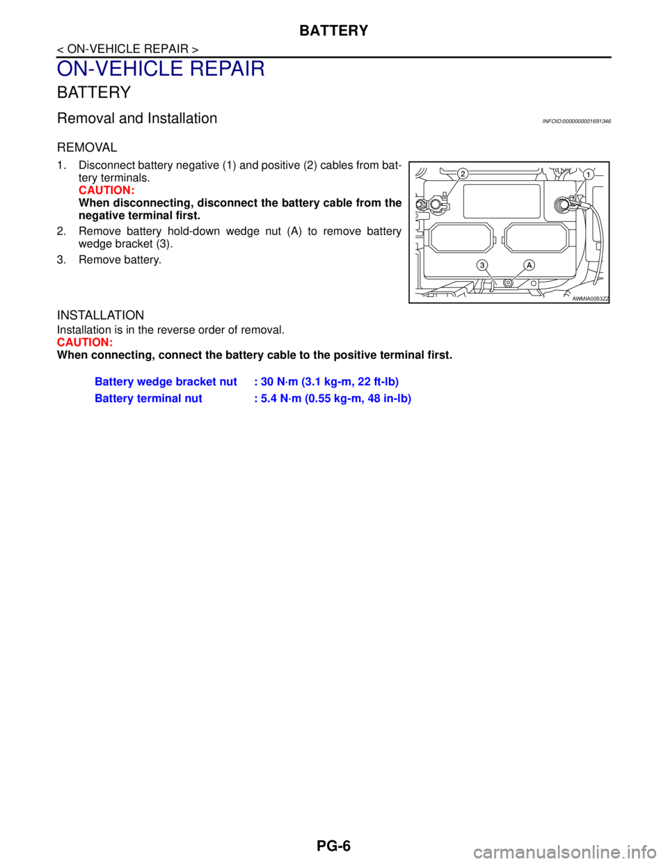
1. Disconnect battery negative (1) and positive (2) cables from bat-
tery terminals.
CAUTION:
When disconnecting, disconnect the battery cable from the
negative terminal first.
2. Remove battery hold-down wedge nut (A) to remove battery
wedge bracket (3).
3. Remove battery.
INSTALLATION
Installation is in the reverse order of removal.
CAUTION:
When connecting, connect the battery cable to the positive terminal first.
AWMIA0053ZZ
Battery wedge bracket nut : 30 N·m (3.1 kg-m, 22 ft-lb)
Battery terminal nut : 5.4 N·m (0.55 kg-m, 48 in-lb)
Page 4462 of 5883
PWC-1
BODY EXTERIOR, DOORS, ROOF & VEHICLE SECURITY
C
D
E
F
G
H
I
J
L
M
SECTION PWC
A
B
PWC
N
O
P
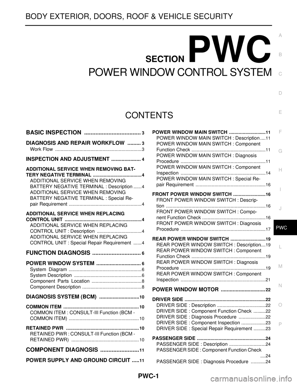
CONTENTS
POWER WINDOW CONTROL SYSTEM
BASIC INSPECTION ....................................3
DIAGNOSIS AND REPAIR WORKFLOW ..........3
Work Flow .................................................................3
INSPECTION AND ADJUSTMENT .....................4
ADDITIONAL SERVICE WHEN REMOVING BAT-
TERY NEGATIVE TERMINAL .....................................
4
ADDITIONAL SERVICE WHEN REMOVING
BATTERY NEGATIVE TERMINAL : Description ......
4
ADDITIONAL SERVICE WHEN REMOVING
BATTERY NEGATIVE TERMINAL : Special Re-
pair Requirement .......................................................
4
ADDITIONAL SERVICE WHEN REPLACING
CONTROL UNIT ..........................................................
4
ADDITIONAL SERVICE WHEN REPLACING
CONTROL UNIT : Description ..................................
4
ADDITIONAL SERVICE WHEN REPLACING
CONTROL UNIT : Special Repair Requirement .......
4
FUNCTION DIAGNOSIS ...............................6
POWER WINDOW SYSTEM ...............................6
System Diagram .......................................................6
System Description ...................................................6
Component Parts Location ......................................8
Component Description .............................................8
DIAGNOSIS SYSTEM (BCM) ............................10
COMMON ITEM .........................................................10
COMMON ITEM : CONSULT-III Function (BCM -
COMMON ITEM) .....................................................
10
RETAINED PWR .......................................................10
RETAINED PWR : CONSULT-III Function (BCM -
RETAINED PWR) ...................................................
10
COMPONENT DIAGNOSIS .........................11
POWER SUPPLY AND GROUND CIRCUIT ......11
POWER WINDOW MAIN SWITCH ............................11
POWER WINDOW MAIN SWITCH : Description ....11
POWER WINDOW MAIN SWITCH : Component
Function Check ........................................................
11
POWER WINDOW MAIN SWITCH : Diagnosis
Procedure ................................................................
11
POWER WINDOW MAIN SWITCH : Component
Inspection ................................................................
14
POWER WINDOW MAIN SWITCH : Special Re-
pair Requirement .....................................................
16
FRONT POWER WINDOW SWITCH .........................16
FRONT POWER WINDOW SWITCH : Descrip-
tion ...........................................................................
16
FRONT POWER WINDOW SWITCH : Compo-
nent Function Check ................................................
16
FRONT POWER WINDOW SWITCH : Diagnosis
Procedure ................................................................
17
REAR POWER WINDOW SWITCH ...........................19
REAR POWER WINDOW SWITCH : Description ....19
REAR POWER WINDOW SWITCH : Component
Function Check ........................................................
19
REAR POWER WINDOW SWITCH : Diagnosis
Procedure ................................................................
19
REAR POWER WINDOW SWITCH : Component
Inspection ................................................................
21
POWER WINDOW MOTOR ..............................22
DRIVER SIDE .............................................................22
DRIVER SIDE : Description .....................................22
DRIVER SIDE : Component Function Check ..........22
DRIVER SIDE : Diagnosis Procedure .....................22
DRIVER SIDE : Component Inspection ...................23
DRIVER SIDE : Special Repair Requirement ..........23
PASSENGER SIDE ....................................................24
PASSENGER SIDE : Description ............................24
PASSENGER SIDE : Component Function Check
....
24
PASSENGER SIDE : Diagnosis Procedure ............24
Page 4463 of 5883

PWC-2
PASSENGER SIDE : Component Inspection .........25
REAR LH ...................................................................25
REAR LH : Description ...........................................25
REAR LH : Component Function Check ................25
REAR LH : Diagnosis Procedure ............................25
REAR LH : Component Inspection .........................26
REAR RH ..................................................................27
REAR RH : Description ..........................................27
REAR RH : Component Function Check ................27
REAR RH : Diagnosis Procedure ...........................27
REAR RH : Component Inspection ........................28
ENCODER .........................................................29
DRIVER SIDE ............................................................29
DRIVER SIDE : Description ....................................29
DRIVER SIDE : Component Function Check .........29
DRIVER SIDE : Diagnosis Procedure ....................29
DRIVER SIDE : Special Repair Requirement .........31
DOOR SWITCH .................................................32
Description ..............................................................32
Component Function Check ...................................32
Diagnosis Procedure ..............................................32
Component Inspection ............................................33
POWER WINDOW LOCK SWITCH ...................34
Description ..............................................................34
Component Function Check ...................................34
Special Repair Requirement ...................................34
ECU DIAGNOSIS ........................................35
BCM (BODY CONTROL MODULE) ..................35
Reference Value .....................................................35
POWER WINDOW MAIN SWITCH ....................36
Reference Value .....................................................36
Wiring Diagram - LHD - ..........................................38
Wiring Diagram - RHD - ..........................................45
Fail Safe .................................................................51
SYMPTOM DIAGNOSIS ............................53
NONE OF THE POWER WINDOWS CAN BE
OPERATED USING ANY SWITCH ...................
53
Diagnosis Procedure ...............................................53
DRIVER SIDE POWER WINDOW ALONE
DOES NOT OPERATE ......................................
54
Diagnosis Procedure ...............................................54
FRONT PASSENGER SIDE POWER WIN-
DOW ALONE DOES NOT OPERATE ...............
55
Diagnosis Procedure ...............................................55
REAR LH SIDE POWER WINDOW ALONE
DOES NOT OPERATE ......................................
56
Diagnosis Procedure ...............................................56
REAR RH SIDE POWER WINDOW ALONE
DOES NOT OPERATE ......................................
57
Diagnosis Procedure ...............................................57
ANTI-PINCH SYSTEM DOES NOT OPERATE
NORMALLY (DRIVER SIDE) ............................
58
Diagnosis Procedure ...............................................58
AUTO OPERATION DOES NOT OPERATE
BUT MANUAL OPERATE NORMALLY
(DRIVER SIDE) ..................................................
59
Diagnosis Procedure ...............................................59
POWER WINDOW RETAINED POWER OP-
ERATION DOES NOT OPERATE PROPERLY
...
60
Diagnosis Procedure ...............................................60
POWER WINDOW LOCK SWITCH DOES
NOT FUNCTION ................................................
61
Diagnosis Procedure ...............................................61
ON-VEHICLE MAINTENANCE ..................62
PRE-INSPECTION FOR DIAGNOSTIC ............62
Basic Inspection ......................................................62
Page 4464 of 5883
DIAGNOSIS AND REPAIR WORKFLOW
PWC-3
< BASIC INSPECTION >
C
D
E
F
G
H
I
J
L
MA
B
PWC
N
O
P
BASIC INSPECTION
DIAGNOSIS AND REPAIR WORKFLOW
Work FlowINFOID:0000000001696360
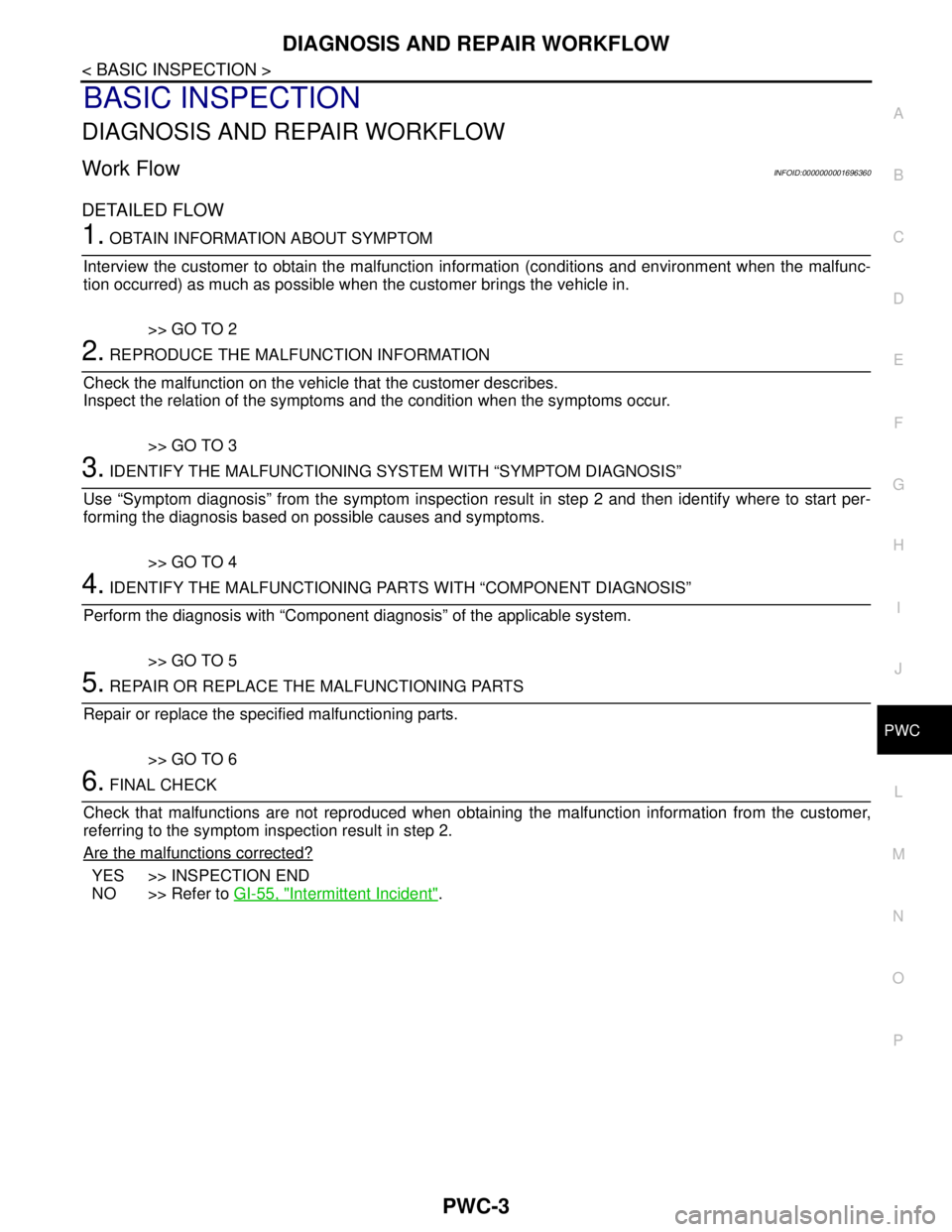
DETAILED FLOW
1. OBTAIN INFORMATION ABOUT SYMPTOM
Interview the customer to obtain the malfunction information (conditions and environment when the malfunc-
tion occurred) as much as possible when the customer brings the vehicle in.
>> GO TO 2
2. REPRODUCE THE MALFUNCTION INFORMATION
Check the malfunction on the vehicle that the customer describes.
Inspect the relation of the symptoms and the condition when the symptoms occur.
>> GO TO 3
3. IDENTIFY THE MALFUNCTIONING SYSTEM WITH “SYMPTOM DIAGNOSIS”
Use “Symptom diagnosis” from the symptom inspection result in step 2 and then identify where to start per-
forming the diagnosis based on possible causes and symptoms.
>> GO TO 4
4. IDENTIFY THE MALFUNCTIONING PARTS WITH “COMPONENT DIAGNOSIS”
Perform the diagnosis with “Component diagnosis” of the applicable system.
>> GO TO 5
5. REPAIR OR REPLACE THE MALFUNCTIONING PARTS
Repair or replace the specified malfunctioning parts.
>> GO TO 6
6. FINAL CHECK
Check that malfunctions are not reproduced when obtaining the malfunction information from the customer,
referring to the symptom inspection result in step 2.
Are the malfunctions corrected?
YES >> INSPECTION END
NO >> Refer to GI-55, "
Intermittent Incident".
Page 4465 of 5883
PWC-4
< BASIC INSPECTION >
INSPECTION AND ADJUSTMENT
INSPECTION AND ADJUSTMENT
ADDITIONAL SERVICE WHEN REMOVING BATTERY NEGATIVE TERMINAL
ADDITIONAL SERVICE WHEN REMOVING BATTERY NEGATIVE TERMINAL : De-
scription
INFOID:0000000001696361
Initial setting is necessary when battery terminal is diconnected.
CAUTION:
The following specified operations are not performed under the non-initialized condition.
• Auto-up operation
Anti-pinch function
Retained power operation
ADDITIONAL SERVICE WHEN REMOVING BATTERY NEGATIVE TERMINAL : Spe-
cial Repair Requirement
INFOID:0000000001696362
INITIALIZATION PROCEDURE
1. Disconnect battery negative terminal or main power window and door lock/unlock switch. Reconnect it
after a minute or more.
2. Turn ignition switch ON.
3. Operate power window switch to fully open the window. (This operation is unnecessary if the window is
already fully open)
4. Continue pulling the power window switch UP (AUTO-UP operation). Even after glass stops at fully closed
position, keep pulling the switch for 4 seconds or more.
5. Inspect anti-pinch function.
CHECK ANTI-PINCH FUNCTION
1. Fully open the door window.
2. Place a piece of wood near fully closed position.
3. Close door glass completely with AUTO-UP.
Check that glass lowers for approximately 150 mm (5.9 in.) or 2 seconds without pinching piece of wood
and stops.
Check that glass does not rise when operating the power window main switch while lowering.
CAUTION:
Do not check with hands and other part of body because they may be pinched. Do not get pinched.
Check that AUTO-UP operates before inspection when system initialization is performed.
It may switch to fail-safe mode if open/close operation is performed continuously. Perform initial set-
ting in that situation. Refer to XX-XX, "*****"
.
Perform initial setting when auto-up operation or anti-pinch function does not operate normally.
Finish initial setting. Otherwise, next operation cannot be done.
1. Auto-up operation
2. Anti-pinch function
3. Retained power operation when ignition switch is OFF.
ADDITIONAL SERVICE WHEN REPLACING CONTROL UNIT
ADDITIONAL SERVICE WHEN REPLACING CONTROL UNIT : Description
INFOID:0000000001696363
Initial setting is necessary when replacing main power window and door lock/unlock switch.
CAUTION:
The following specified operations are not performed under the non-initialized condition.
Auto-up operation
Anti-pinch function
Retained power operation
ADDITIONAL SERVICE WHEN REPLACING CONTROL UNIT : Special Repair Re-
quirement
INFOID:0000000001696364
INITIALIZATION PROCEDURE
Page 4466 of 5883
INSPECTION AND ADJUSTMENT
PWC-5
< BASIC INSPECTION >
C
D
E
F
G
H
I
J
L
MA
B
PWC
N
O
P
1. Disconnect battery negative terminal or main power window and door lock/unlock switch. Reconnect it
after a minute or more.
2. Turn ignition switch ON.
3. Operate power window switch to fully open the window. (This operation is unnecessary if the window is
already fully open)
4. Continue pulling the power window switch UP (AUTO-UP operation). Even after glass stops at fully closed
position, keep pulling the switch for 4 seconds or more.
5. Inspect anti-pinch function.
CHECK ANTI-PINCH FUNCTION
1. Fully open the door window.
2. Place a piece of wood near fully closed position.
3. Close door glass completely with AUTO-UP.
Check that glass lowers for approximately 150 mm (5.9 in.) or 2 seconds without pinching piece of wood
and stops.
Check that glass does not rise when operating the main power window and door lock/unlock switch while
lowering.
CAUTION:
Do not check with hands and other part of body because they may be pinched. Do not get pinched.
Check that AUTO-UP operates before inspection when system initialization is performed.
It may switch to fail-safe mode if open/close operation is performed continuously. Perform initial set-
ting in that situation. Refer to XX-XX, "*****"
.
Perform initial setting when auto-up operation or anti-pinch function does not operate normally.
Finish initial setting. Otherwise, next operation cannot be done.
1. Auto-up operation
2. Anti-pinch function
3. Retained power operation when ignition switch is OFF.
Page 4467 of 5883
PWC-6
< FUNCTION DIAGNOSIS >
POWER WINDOW SYSTEM
FUNCTION DIAGNOSIS
POWER WINDOW SYSTEM
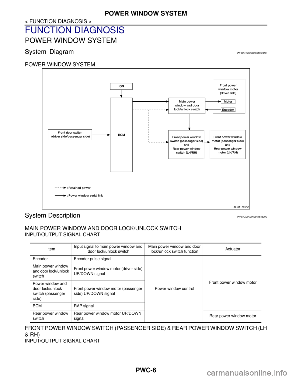
System DiagramINFOID:0000000001696298
POWER WINDOW SYSTEM
System DescriptionINFOID:0000000001696299
MAIN POWER WINDOW AND DOOR LOCK/UNLOCK SWITCH
INPUT/OUTPUT SIGNAL CHART
FRONT POWER WINDOW SWITCH (PASSENGER SIDE) & REAR POWER WINDOW SWITCH (LH
& RH)
INPUT/OUTPUT SIGNAL CHART
ALKIA1093GB
ItemInput signal to main power window and
door lock/unlock switchMain power window and door
lock/unlock switch functionActuator
Encoder Encoder pulse signal
Power window controlFront power window motor Main power window
and door lock/unlock
switchFront power window motor (driver side)
UP/DOWN signal
Power window and
door lock/unlock
switch (passenger
side) Front power window motor (passenger
side) UP/DOWN signal
BCM RAP signal
Rear power window
switchRear power window motor UP/DOWN
signalRear power window motor
Page 4468 of 5883
POWER WINDOW SYSTEM
PWC-7
< FUNCTION DIAGNOSIS >
C
D
E
F
G
H
I
J
L
MA
B
PWC
N
O
P
POWER WINDOW OPERATION
Power window system is operable during the retained power operation timer after turning ignition switch ON
and OFF.
Main power window and door lock/unlock switch can open/close all windows.
Front & rear power window switches can open/close the corresponding windows.
POWER WINDOW AUTO-OPERATION (FRONT DRIVER SIDE)
AUTO UP/DOWN operation can be performed when main power window and door lock/unlock switch turns
to AUTO.
Encoder continues detecting the movement of power window motor and transmits to main power window
and door lock/unlock switch as the encoder pulse signal while power window motor is operating.
Main power window and door lock/unlock switch reads the changes of encoder signal and stops AUTO oper-
ation when door glass is at fully opened/closed position.
Power window motor is operable in case encoder is malfunctioning.
RETAINED POWER OPERATION
Retained power operation is an additional power supply function that enables power window system to oper-
ate during the 45 seconds even when ignition switch is turned OFF
Retained power function cancel conditions Front door CLOSE (door switch OFF)→OPEN (door switch ON).
When ignition switch is ON.
When timer time passes (45 seconds).
POWER WINDOW LOCK
Ground circuit inside main power window and door lock/unlock switch shuts off when power window lock
switch is ON. This inhibits power window switch operation except with the main power window and door lock/
unlock switch.
ANTI-PINCH OPERATION (FRONT DRIVER SIDE)
Pinch foreign material in the door glass during AUTO-UP operation,and it is the anti-pinch function that low-
ers the door glass 150 mm (5.9 in.) or 2 seconds when detected.
Encoder continues detecting the movement of power window motor and transmits to main power window
and door lock/unlock switch as the encoder pulse signal while power window motor is operating.
Resistance is applied to the power window motor rotation that changes the frequency of encoder pulse sig-
nal if foreign material is trapped in the door glass.
Power window switch controls to lower the window glass for 150 mm (5.9 in.) or 2 seconds after it detects
encoder pulse signal frequency change.
OPERATION CONDITION
When door glass AUTO-UP operation is performed (anti-pinch function does not operate just before the door
glass closes and is fully closed)
NOTE:
Depending on environment and driving conditions, if a similar impact or load is applied to the door glass, it
may lower.
Item Input signal to front power window
switch (passenger side) & rear power
window switch (LH & RH)Front power window switch
(passenger side) & rear power
window switch (LH & RH) func-
tionActuator
Front power window
switch (passenger
side)Front power window motor (passen-
ger side) UP/DOWN signal
Power window controlFront power window motor
(passenger side)
Rear power window
switch (LH & RH)Rear power window motor (LH & RH)
UP/DOWN signalRear power window motor (LH
& RH)
Page 4469 of 5883
PWC-8
< FUNCTION DIAGNOSIS >
POWER WINDOW SYSTEM
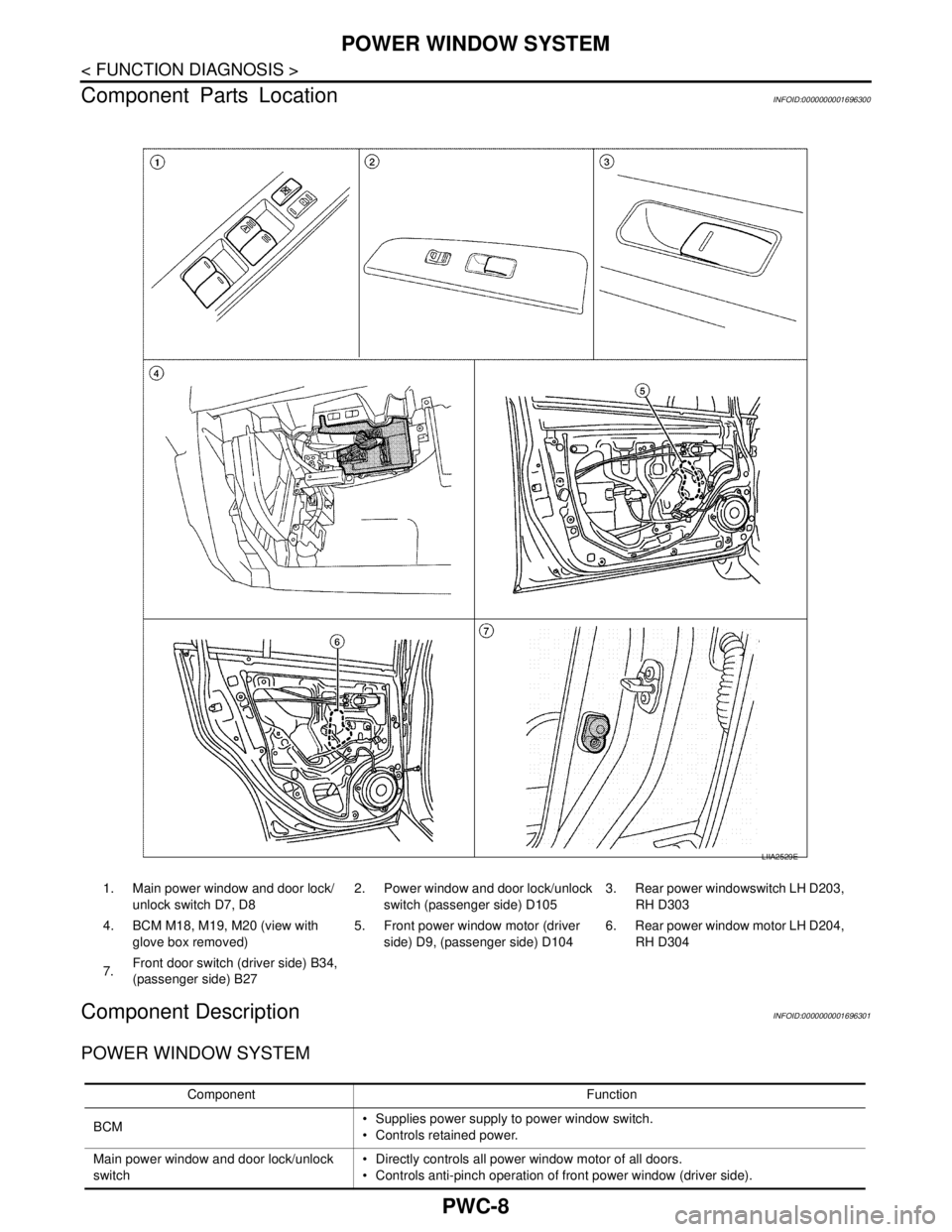
Component Parts Location
INFOID:0000000001696300
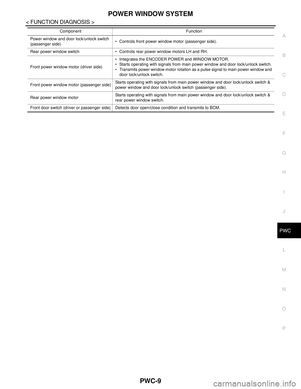
Component DescriptionINFOID:0000000001696301
POWER WINDOW SYSTEM
LIIA2529E
1. Main power window and door lock/
unlock switch D7, D82. Power window and door lock/unlock
switch (passenger side) D1053. Rear power windowswitch LH D203,
RH D303
4. BCM M18, M19, M20 (view with
glove box removed)5. Front power window motor (driver
side) D9, (passenger side) D1046. Rear power window motor LH D204,
RH D304
7.Front door switch (driver side) B34,
(passenger side) B27
Component Function
BCM Supplies power supply to power window switch.
Controls retained power.
Main power window and door lock/unlock
switch Directly controls all power window motor of all doors.
Controls anti-pinch operation of front power window (driver side).
Page 4470 of 5883
POWER WINDOW SYSTEM
PWC-9
< FUNCTION DIAGNOSIS >
C
D
E
F
G
H
I
J
L
MA
B
PWC
N
O
P
Power window and door lock/unlock switch
(passenger side) Controls front power window motor (passenger side).
Rear power window switch Controls rear power window motors LH and RH.
Front power window motor (driver side) Integrates the ENCODER POWER and WINDOW MOTOR.
Starts operating with signals from main power window and door lock/unlock switch.
Transmits power window motor rotation as a pulse signal to main power window and
door lock/unlock switch.
Front power window motor (passenger side)Starts operating with signals from main power window and door lock/unlock switch &
power window and door lock/unlock switch (passenger side).
Rear power window motorStarts operating with signals from main power window and door lock/unlock switch &
rear power window switch.
Front door switch (driver or passenger side) Detects door open/close condition and transmits to BCM.Component Function