NISSAN TIIDA 2007 Service Repair Manual
TIIDA 2007
NISSAN
NISSAN
https://www.carmanualsonline.info/img/5/57395/w960_57395-0.png
NISSAN TIIDA 2007 Service Repair Manual
Trending: Pri pressure, remote start, oil dipstick, glove box, front cowl, Abs CAN line, brake rotor
Page 5741 of 5883
WCS-26
< COMPONENT DIAGNOSIS >
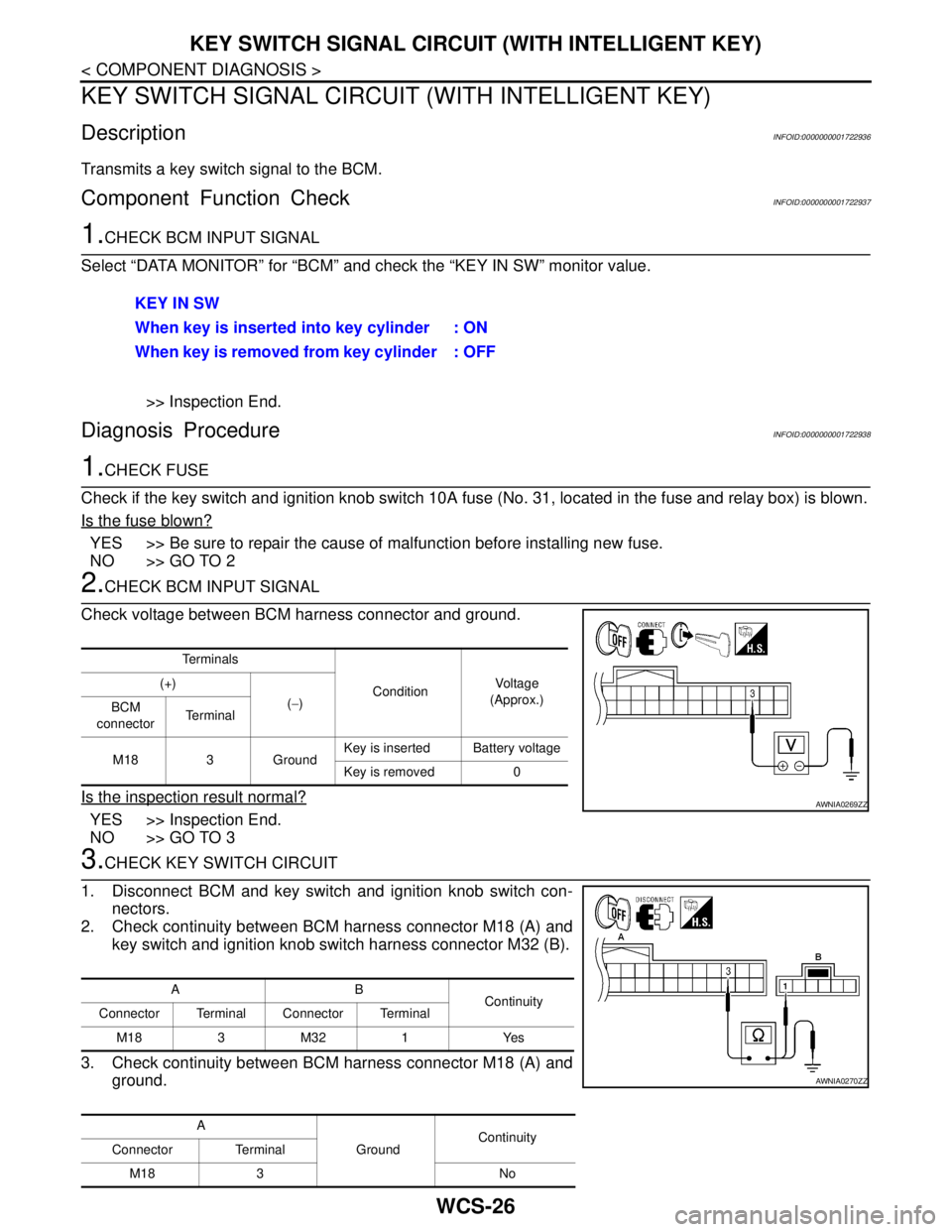
KEY SWITCH SIGNAL CIRCUIT (WITH INTELLIGENT KEY)
KEY SWITCH SIGNAL CIRCUIT (WITH INTELLIGENT KEY)
DescriptionINFOID:0000000001722936
Transmits a key switch signal to the BCM.
Component Function CheckINFOID:0000000001722937
1.CHECK BCM INPUT SIGNAL
Select “DATA MONITOR” for “BCM” and check the “KEY IN SW” monitor value.
>> Inspection End.
Diagnosis ProcedureINFOID:0000000001722938
1.CHECK FUSE
Check if the key switch and ignition knob switch 10A fuse (No. 31, located in the fuse and relay box) is blown.
Is the fuse blown?
YES >> Be sure to repair the cause of malfunction before installing new fuse.
NO >> GO TO 2
2.CHECK BCM INPUT SIGNAL
Check voltage between BCM harness connector and ground.
Is the inspection result normal?
YES >> Inspection End.
NO >> GO TO 3
3.CHECK KEY SWITCH CIRCUIT
1. Disconnect BCM and key switch and ignition knob switch con-
nectors.
2. Check continuity between BCM harness connector M18 (A) and
key switch and ignition knob switch harness connector M32 (B).
3. Check continuity between BCM harness connector M18 (A) and
ground.KEY IN SW
When key is inserted into key cylinder : ON
When key is removed from key cylinder : OFF
Te r m i n a l s
ConditionVo l ta g e
(Approx.) (+)
(−)
BCM
connectorTe r m i n a l
M18 3 GroundKey is inserted Battery voltage
Key is removed 0
AWNIA0269ZZ
AB
Continuity
Connector Terminal Connector Terminal
M183M321 Yes
A
GroundContinuity
Connector Terminal
M18 3 No
AWNIA0270ZZ
Page 5742 of 5883
WCS
KEY SWITCH SIGNAL CIRCUIT (WITH INTELLIGENT KEY)
WCS-27
< COMPONENT DIAGNOSIS >
C
D
E
F
G
H
I
J
K
L
MB A
O
P
Is the inspection result normal?
YES >> GO TO 4
NO >> Repair harness or connector.
4.CHECK KEY SWITCH POWER SUPPLY CIRCUIT
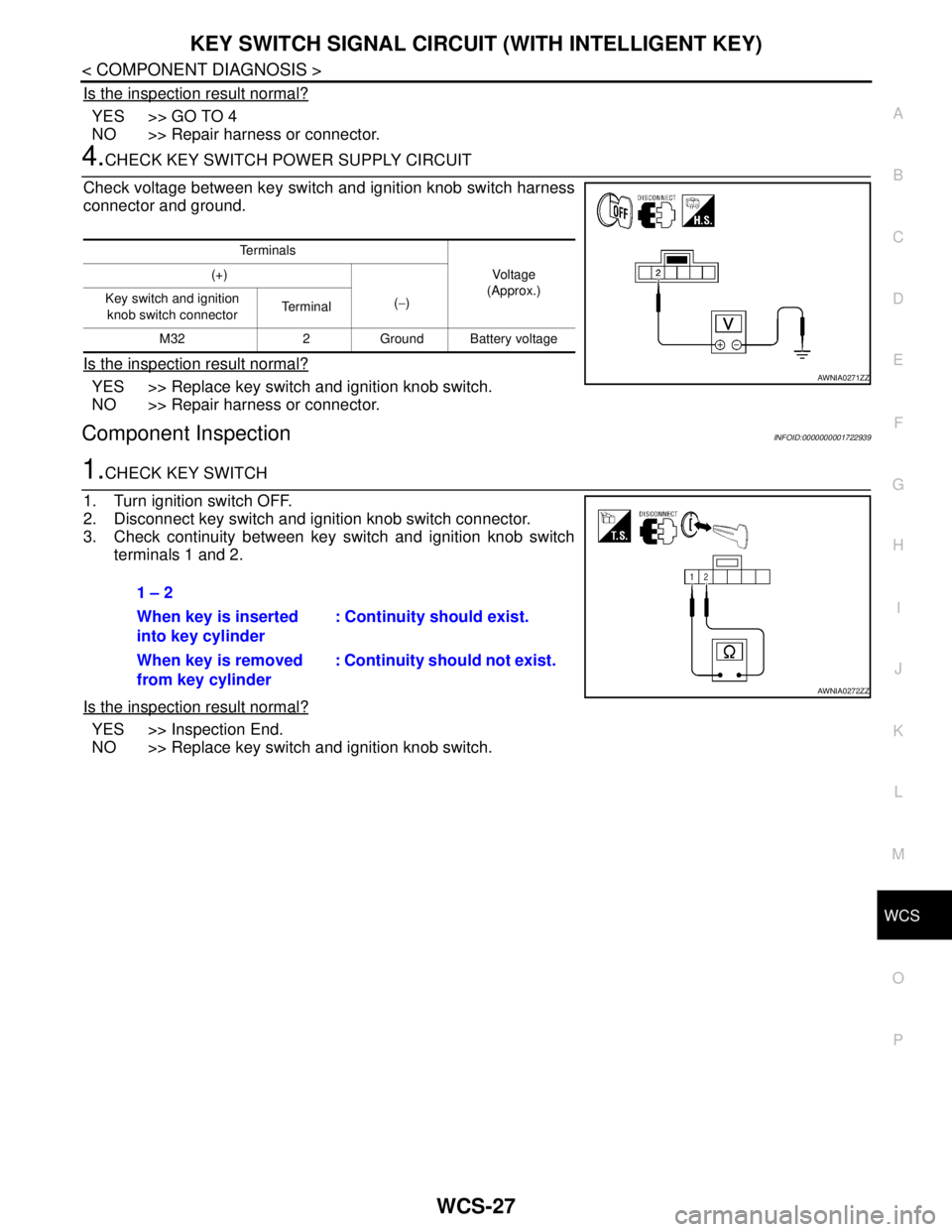
Check voltage between key switch and ignition knob switch harness
connector and ground.
Is the inspection result normal?
YES >> Replace key switch and ignition knob switch.
NO >> Repair harness or connector.
Component InspectionINFOID:0000000001722939
1.CHECK KEY SWITCH
1. Turn ignition switch OFF.
2. Disconnect key switch and ignition knob switch connector.
3. Check continuity between key switch and ignition knob switch
terminals 1 and 2.
Is the inspection result normal?
YES >> Inspection End.
NO >> Replace key switch and ignition knob switch.
Te r m i n a l s
Vo l ta g e
(Approx.) (+)
(−) Key switch and ignition
knob switch connector Te r m i n a l
M32 2 Ground Battery voltage
AWNIA0271ZZ
1 – 2
When key is inserted
into key cylinder: Continuity should exist.
When key is removed
from key cylinder: Continuity should not exist.
AWNIA0272ZZ
Page 5743 of 5883
WCS-28
< COMPONENT DIAGNOSIS >
KEY SWITCH SIGNAL CIRCUIT (WITHOUT INTELLIGENT KEY)
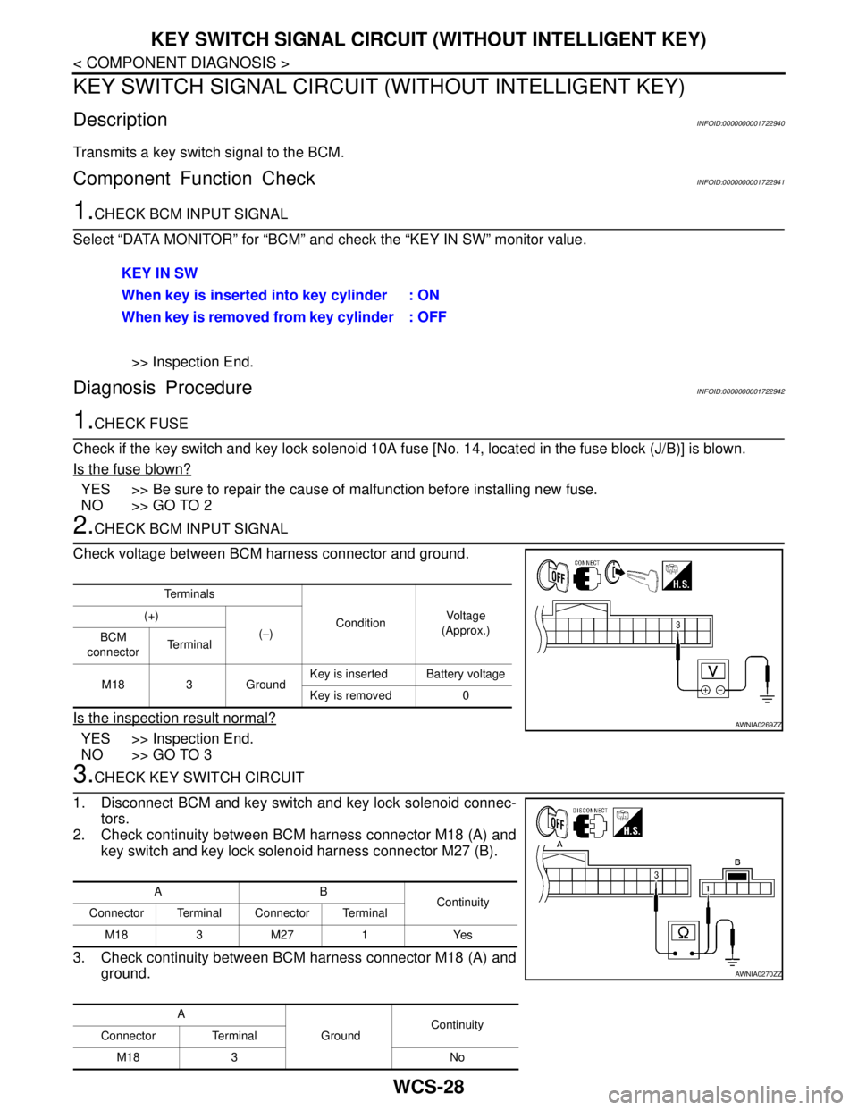
KEY SWITCH SIGNAL CIRCUIT (WITHOUT INTELLIGENT KEY)
DescriptionINFOID:0000000001722940
Transmits a key switch signal to the BCM.
Component Function CheckINFOID:0000000001722941
1.CHECK BCM INPUT SIGNAL
Select “DATA MONITOR” for “BCM” and check the “KEY IN SW” monitor value.
>> Inspection End.
Diagnosis ProcedureINFOID:0000000001722942
1.CHECK FUSE
Check if the key switch and key lock solenoid 10A fuse [No. 14, located in the fuse block (J/B)] is blown.
Is the fuse blown?
YES >> Be sure to repair the cause of malfunction before installing new fuse.
NO >> GO TO 2
2.CHECK BCM INPUT SIGNAL
Check voltage between BCM harness connector and ground.
Is the inspection result normal?
YES >> Inspection End.
NO >> GO TO 3
3.CHECK KEY SWITCH CIRCUIT
1. Disconnect BCM and key switch and key lock solenoid connec-
tors.
2. Check continuity between BCM harness connector M18 (A) and
key switch and key lock solenoid harness connector M27 (B).
3. Check continuity between BCM harness connector M18 (A) and
ground.KEY IN SW
When key is inserted into key cylinder : ON
When key is removed from key cylinder : OFF
Te r m i n a l s
ConditionVo l ta g e
(Approx.) (+)
(−)
BCM
connectorTe r m i n a l
M18 3 GroundKey is inserted Battery voltage
Key is removed 0
AWNIA0269ZZ
AB
Continuity
Connector Terminal Connector Terminal
M183M271 Yes
A
GroundContinuity
Connector Terminal
M18 3 No
AWNIA0270ZZ
Page 5744 of 5883
WCS
KEY SWITCH SIGNAL CIRCUIT (WITHOUT INTELLIGENT KEY)
WCS-29
< COMPONENT DIAGNOSIS >
C
D
E
F
G
H
I
J
K
L
MB A
O
P
Is the inspection result normal?
YES >> GO TO 4
NO >> Repair harness or connector.
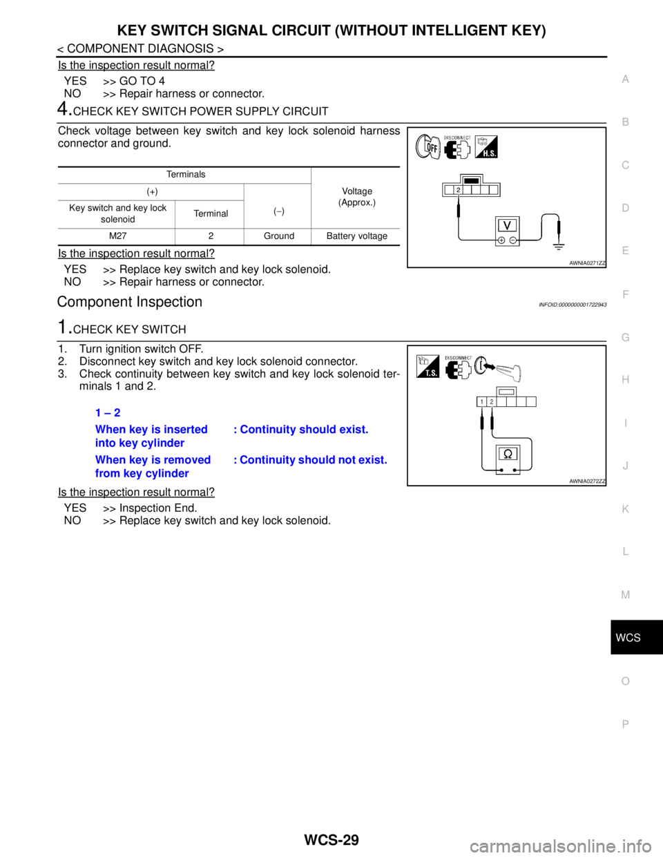
4.CHECK KEY SWITCH POWER SUPPLY CIRCUIT
Check voltage between key switch and key lock solenoid harness
connector and ground.
Is the inspection result normal?
YES >> Replace key switch and key lock solenoid.
NO >> Repair harness or connector.
Component InspectionINFOID:0000000001722943
1.CHECK KEY SWITCH
1. Turn ignition switch OFF.
2. Disconnect key switch and key lock solenoid connector.
3. Check continuity between key switch and key lock solenoid ter-
minals 1 and 2.
Is the inspection result normal?
YES >> Inspection End.
NO >> Replace key switch and key lock solenoid.
Te r m i n a l s
Vo l ta g e
(Approx.) (+)
(−) Key switch and key lock
solenoid Te r m i n a l
M27 2 Ground Battery voltage
AWNIA0271ZZ
1 – 2
When key is inserted
into key cylinder: Continuity should exist.
When key is removed
from key cylinder: Continuity should not exist.
AWNIA0272ZZ
Page 5745 of 5883
WCS-30
< COMPONENT DIAGNOSIS >
PARKING BRAKE SWITCH SIGNAL CIRCUIT
PARKING BRAKE SWITCH SIGNAL CIRCUIT
DescriptionINFOID:0000000001722969
Transmits the parking brake switch signal to the combination meter.
Component Function CheckINFOID:0000000001724686
1.COMBINATION METER INPUT SIGNAL
1. Start engine.
2. Monitor “BRAKE” warning lamp while applying and releasing the parking brake.
>> Inspection End.
Diagnosis ProcedureINFOID:0000000001724687
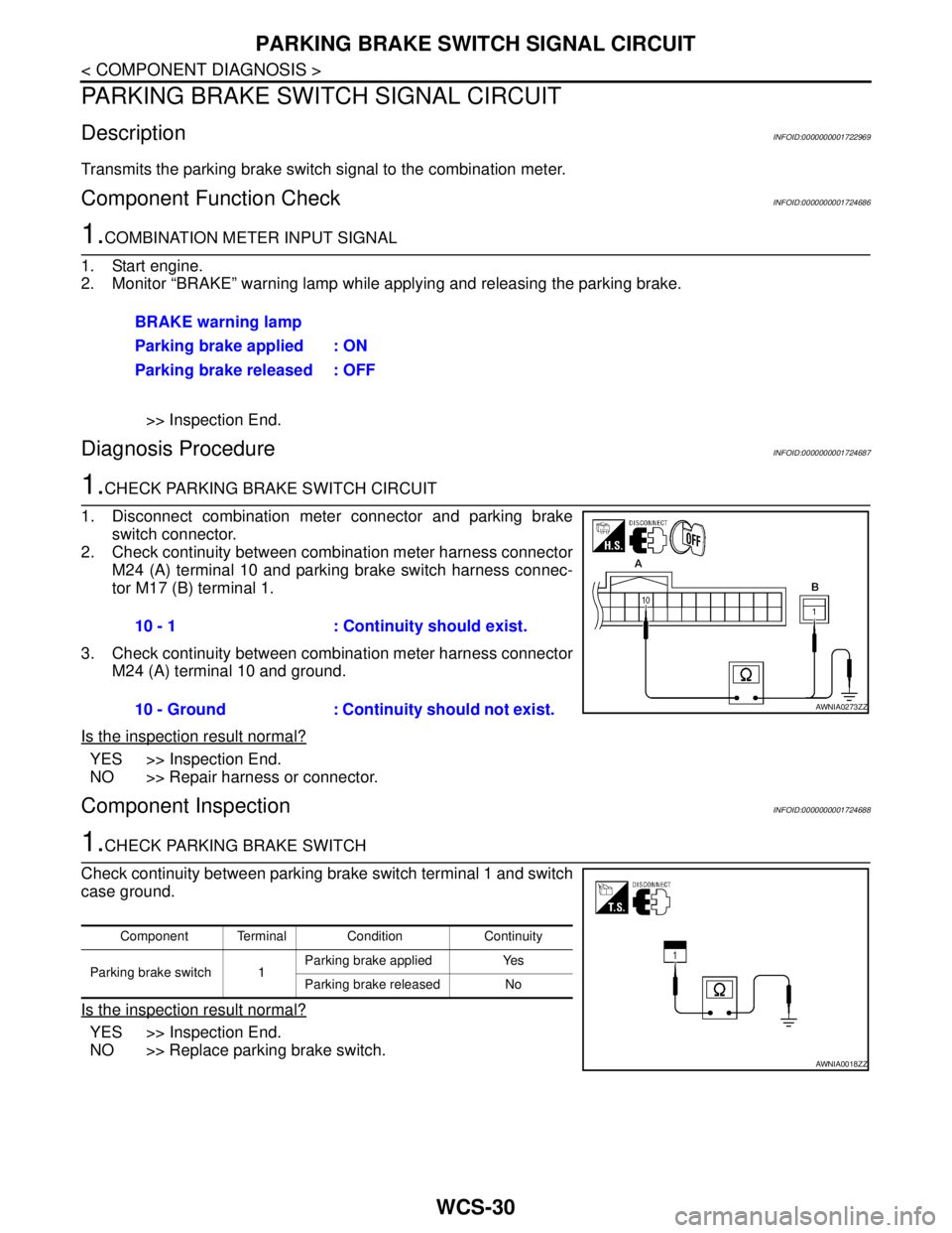
1.CHECK PARKING BRAKE SWITCH CIRCUIT
1. Disconnect combination meter connector and parking brake
switch connector.
2. Check continuity between combination meter harness connector
M24 (A) terminal 10 and parking brake switch harness connec-
tor M17 (B) terminal 1.
3. Check continuity between combination meter harness connector
M24 (A) terminal 10 and ground.
Is the inspection result normal?
YES >> Inspection End.
NO >> Repair harness or connector.
Component InspectionINFOID:0000000001724688
1.CHECK PARKING BRAKE SWITCH
Check continuity between parking brake switch terminal 1 and switch
case ground.
Is the inspection result normal?
YES >> Inspection End.
NO >> Replace parking brake switch.BRAKE warning lamp
Parking brake applied : ON
Parking brake released : OFF
10 - 1 : Continuity should exist.
10 - Ground : Continuity should not exist.
AWNIA0273ZZ
Component Terminal Condition Continuity
Parking brake switch 1Parking brake applied Yes
Parking brake released No
AWNIA0018ZZ
Page 5746 of 5883
WCS
WARNING CHIME SYSTEM
WCS-31
< COMPONENT DIAGNOSIS >
C
D
E
F
G
H
I
J
K
L
MB A
O
P
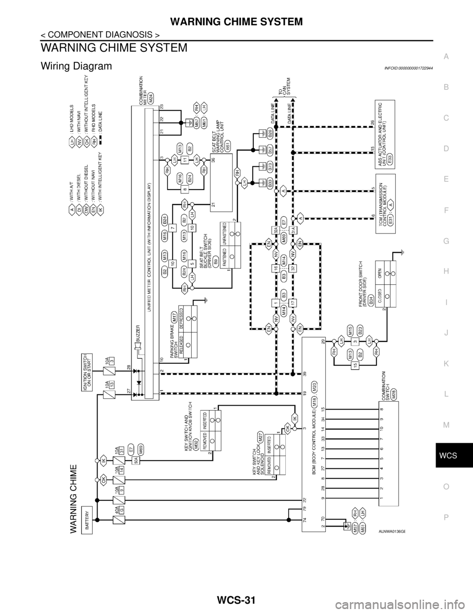
WARNING CHIME SYSTEM
Wiring DiagramINFOID:0000000001722944
ALNWA0136GB
Page 5747 of 5883
WCS-32
< COMPONENT DIAGNOSIS >
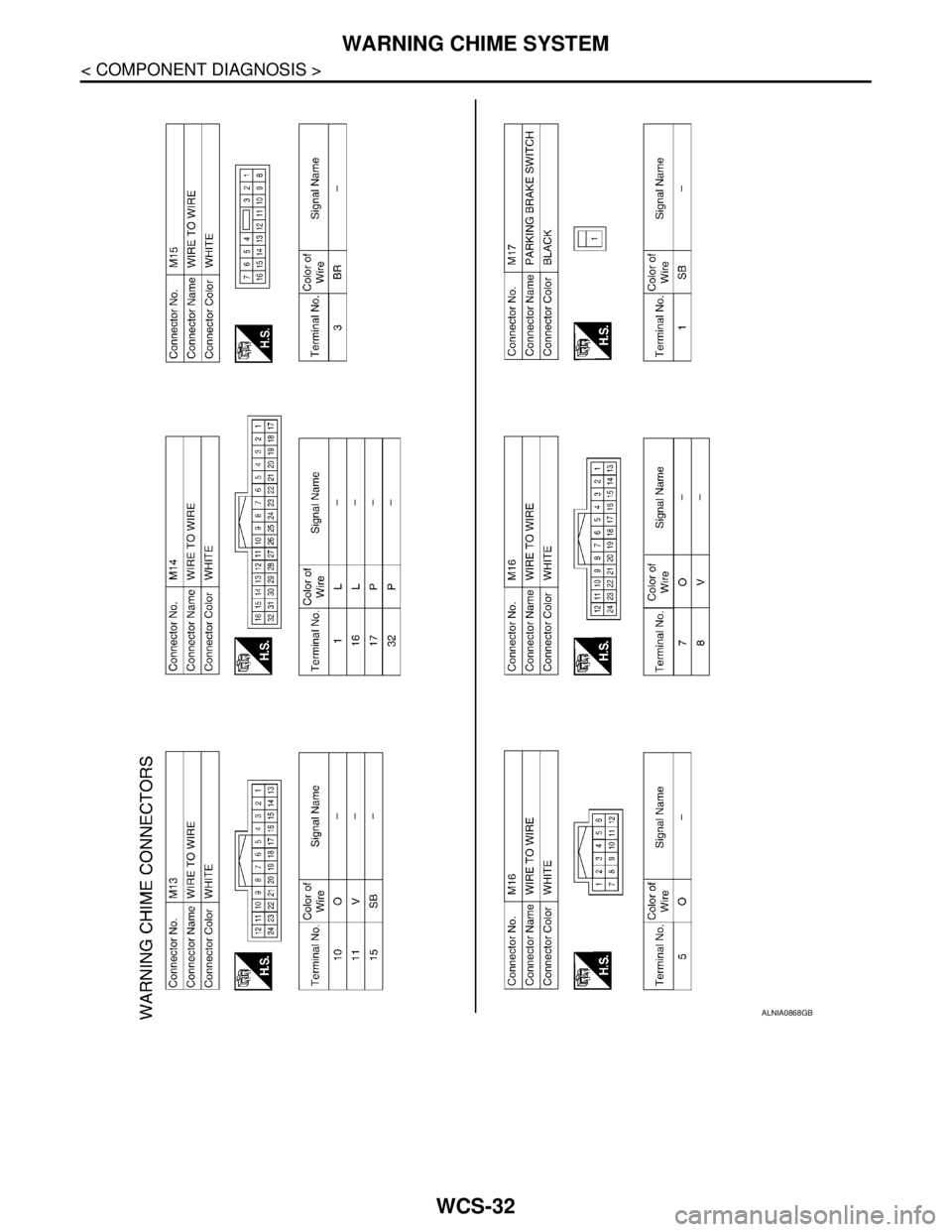
WARNING CHIME SYSTEM
ALNIA0868GB
Page 5748 of 5883
WCS
WARNING CHIME SYSTEM
WCS-33
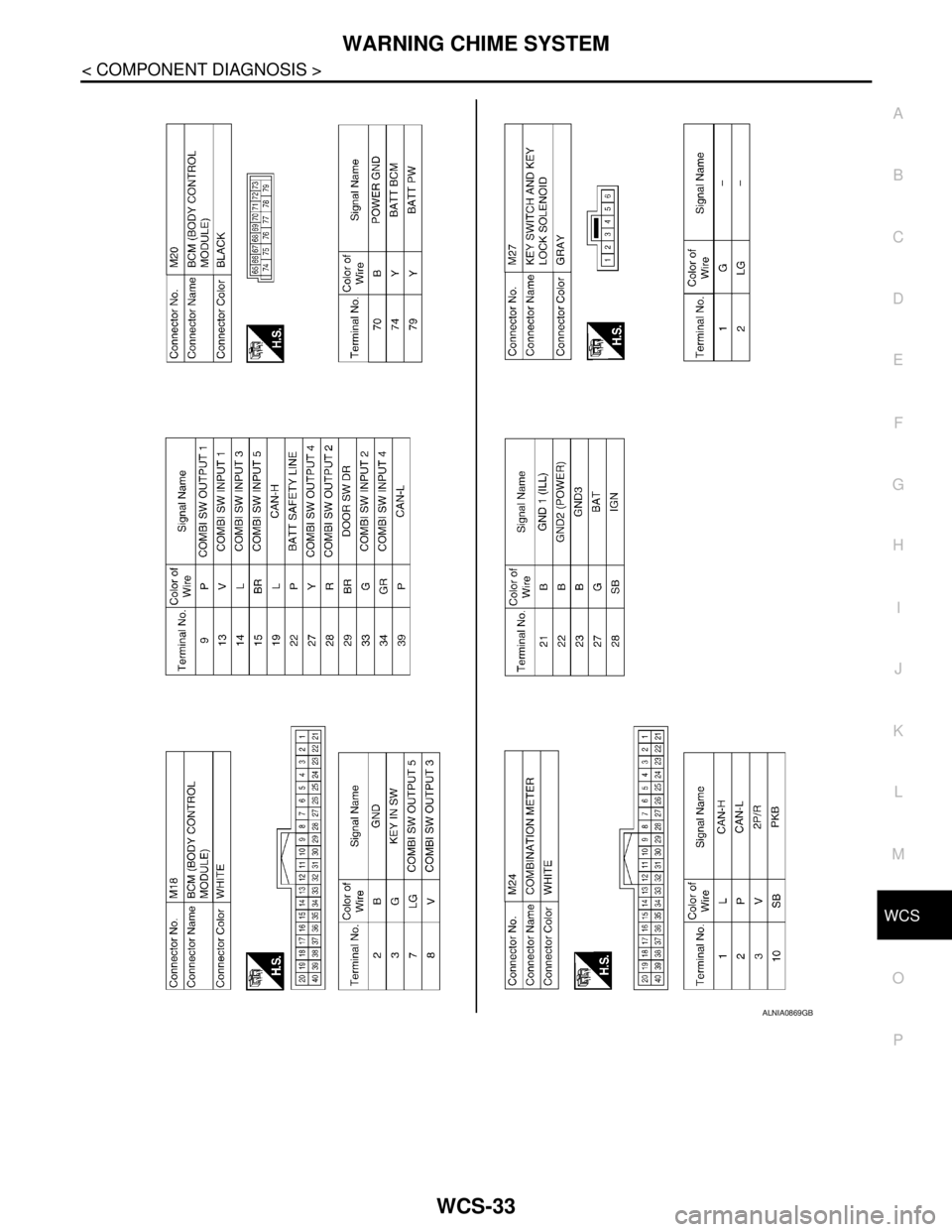
< COMPONENT DIAGNOSIS >
C
D
E
F
G
H
I
J
K
L
MB A
O
P
ALNIA0869GB
Page 5749 of 5883
WCS-34
< COMPONENT DIAGNOSIS >
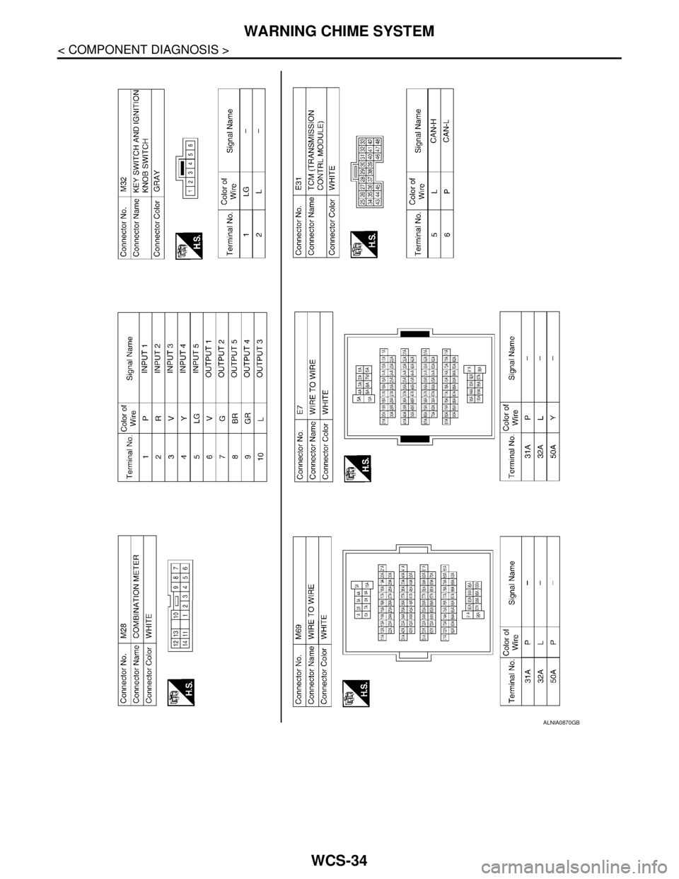
WARNING CHIME SYSTEM
ALNIA0870GB
Page 5750 of 5883
WCS
WARNING CHIME SYSTEM
WCS-35
< COMPONENT DIAGNOSIS >
C
D
E
F
G
H
I
J
K
L
MB A
O
P
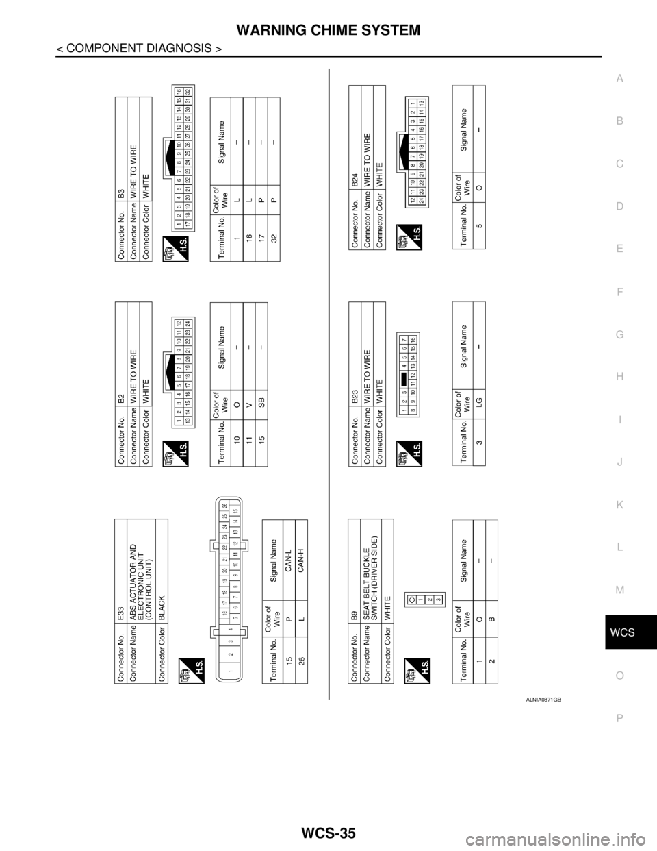
ALNIA0871GB
Trending: reset sun roof, engine oil type, Fan system, PWO, fuel tank removal, RECOMMENDED FLUIDS AND LUBRICANTS, gearbox


