Fuse location NISSAN TIIDA 2007 Service Repair Manual
[x] Cancel search | Manufacturer: NISSAN, Model Year: 2007, Model line: TIIDA, Model: NISSAN TIIDA 2007Pages: 5883, PDF Size: 78.95 MB
Page 3034 of 5883
HEADLAMP (HI) CIRCUIT
EXL-33
< COMPONENT DIAGNOSIS >
C
D
E
F
G
H
I
J
K
MA
B
EXL
N
O
P
HEADLAMP (HI) CIRCUIT
HEADLAMP (HALOGEN)
HEADLAMP (HALOGEN) : DescriptionINFOID:0000000001523259
The IPDM E/R (intelligent power distribution module engine room) controls the headlamp high relay based on
inputs from the BCM via the CAN communication lines. When the headlamp high relay is energized, power
flows through fuses 34 and 35, located in the IPDM E/R. Power then flows to the front combination lamps to
the headlamp high beam.
HEADLAMP (HALOGEN) : Component Function CheckINFOID:0000000001523260
1.CHECK HEADLAMP (HI) OPERATION
WITHOUT CONSULT-III
1. Start IPDM E/R auto active test. Refer to XX-XX, "*****"
.
2. Check that the headlamp switches to the high beam.
NOTE:
HI/LO is repeated 1 second each when using the IPDM E/R auto active test.
CONSULT-III
1. Select "EXTERNAL LAMP" of IPDM E/R active test item.
2. With operating the test items, check that the headlamp switches to the high beam.
Does the headlamp switch to the high beam?
YES >> Headlamp (HI) circuit is normal.
NO >> Refer to EXL-33, "
HEADLAMP (HALOGEN) : Diagnosis Procedure".
HEADLAMP (HALOGEN) : Diagnosis ProcedureINFOID:0000000001523261
1.CHECK HEADLAMP (HI) FUSES
1. Turn the ignition switch OFF.
2. Check that the following fuses are not open.
Is the fuse open?
YES >> Repair the harness and replace the fuse.
NO >> GO TO 2
2.CHECK HEADLAMP (HI) OUTPUT VOLTAGE
CONSULT-III ACTIVE TEST
1. Turn the ignition switch OFF.
2. Disconnect the front combination lamp connector.
3. Turn the ignition switch ON.
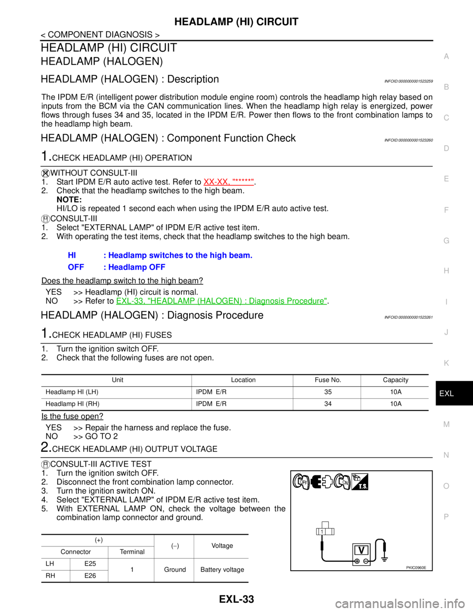
4. Select "EXTERNAL LAMP" of IPDM E/R active test item.
5. With EXTERNAL LAMP ON, check the voltage between the
combination lamp connector and ground.HI : Headlamp switches to the high beam.
OFF : Headlamp OFF
Unit Location Fuse No. Capacity
Headlamp HI (LH) IPDM E/R 35 10A
Headlamp HI (RH) IPDM E/R 34 10A
(+)
(−)Voltage
Connector Terminal
LH E25
1 Ground Battery voltage
RH E26
PKIC0960E
Page 3036 of 5883
HEADLAMP (HI) CIRCUIT
EXL-35
< COMPONENT DIAGNOSIS >
C
D
E
F
G
H
I
J
K
MA
B
EXL
N
O
P
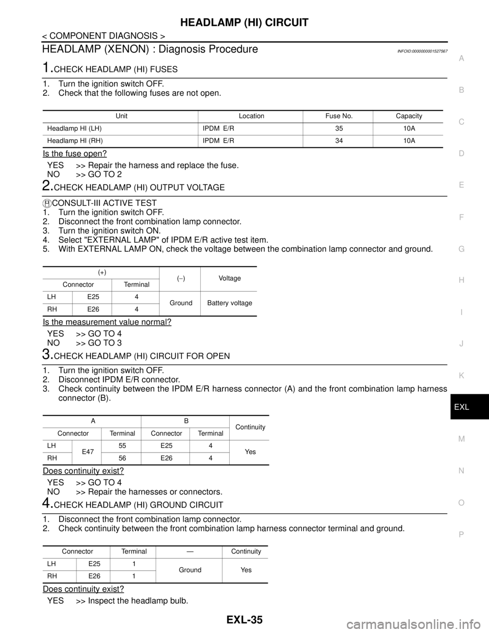
HEADLAMP (XENON) : Diagnosis ProcedureINFOID:0000000001527567
1.CHECK HEADLAMP (HI) FUSES
1. Turn the ignition switch OFF.
2. Check that the following fuses are not open.
Is the fuse open?
YES >> Repair the harness and replace the fuse.
NO >> GO TO 2
2.CHECK HEADLAMP (HI) OUTPUT VOLTAGE
CONSULT-III ACTIVE TEST
1. Turn the ignition switch OFF.
2. Disconnect the front combination lamp connector.
3. Turn the ignition switch ON.
4. Select "EXTERNAL LAMP" of IPDM E/R active test item.
5. With EXTERNAL LAMP ON, check the voltage between the combination lamp connector and ground.
Is the measurement value normal?
YES >> GO TO 4
NO >> GO TO 3
3.CHECK HEADLAMP (HI) CIRCUIT FOR OPEN
1. Turn the ignition switch OFF.
2. Disconnect IPDM E/R connector.
3. Check continuity between the IPDM E/R harness connector (A) and the front combination lamp harness
connector (B).
Does continuity exist?
YES >> GO TO 4
NO >> Repair the harnesses or connectors.
4.CHECK HEADLAMP (HI) GROUND CIRCUIT
1. Disconnect the front combination lamp connector.
2. Check continuity between the front combination lamp harness connector terminal and ground.
Does continuity exist?
YES >> Inspect the headlamp bulb.
Unit Location Fuse No. Capacity
Headlamp HI (LH) IPDM E/R 35 10A
Headlamp HI (RH) IPDM E/R 34 10A
(+)
(−)Voltage
Connector Terminal
LH E25 4
Ground Battery voltage
RH E26 4
AB
Continuity
Connector Terminal Connector Terminal
LH
E4755 E25 4
Ye s
RH 56 E26 4
Connector Terminal — Continuity
LH E25 1
Ground Yes
RH E26 1
Page 3038 of 5883
HEADLAMP (LO) CIRCUIT
EXL-37
< COMPONENT DIAGNOSIS >
C
D
E
F
G
H
I
J
K
MA
B
EXL
N
O
P
HEADLAMP (LO) CIRCUIT
HEADLAMP (HALOGEN)
HEADLAMP (HALOGEN) : DescriptionINFOID:0000000001523262
The IPDM E/R (intelligent power distribution module engine room) controls the headlamp low relay based on
inputs from the BCM via the CAN communication lines. When the headlamp low relay is energized, power
flows through fuses 40 and 41, located in the IPDM E/R. Power then flows to the front combination lamps to
the headlamp low beam.
HEADLAMP (HALOGEN) : Component Function CheckINFOID:0000000001523263
1.CHECK HEADLAMP (LO) OPERATION
WITHOUT CONSULT-III
1. Start IPDM E/R auto active test. Refer to XX-XX, "*****"
.
2. Check that the headlamp is turned ON.
NOTE:
HI/LO is repeated 1 second each when using the IPDM E/R auto active test.
CONSULT-III
1. Select "EXTERNAL LAMP" of IPDM E/R active test item.
2. With operating the test items, check that the headlamp is turned ON.
Is the headlamp turned ON?
YES >> Headlamp (LO) is normal.
NO >> Refer to EXL-37, "
HEADLAMP (HALOGEN) : Diagnosis Procedure".
HEADLAMP (HALOGEN) : Diagnosis ProcedureINFOID:0000000001523264
1.CHECK HEADLAMP (LO) FUSES
1. Turn the ignition switch OFF.
2. Check that the following fuses are not open.
Is the fuse open?
YES >> Repair the harness and replace the fuse.
NO >> GO TO 2
2.CHECK HEADLAMP (LO) OUTPUT VOLTAGE
CONSULT-III
1. Turn the ignition switch OFF.
2. Disconnect the front combination lamp connector.
3. Turn the ignition switch ON.
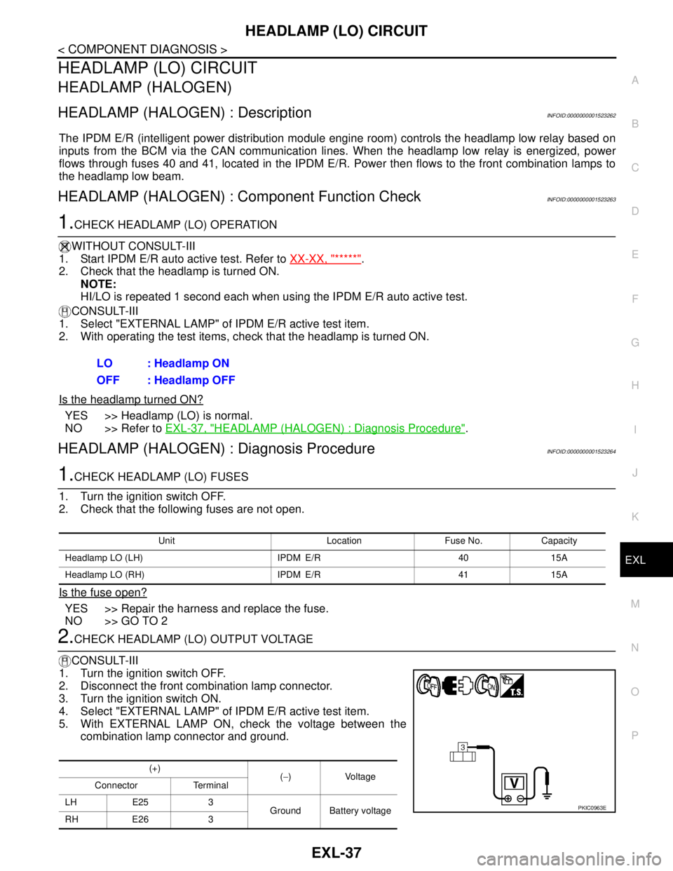
4. Select "EXTERNAL LAMP" of IPDM E/R active test item.
5. With EXTERNAL LAMP ON, check the voltage between the
combination lamp connector and ground.LO : Headlamp ON
OFF : Headlamp OFF
Unit Location Fuse No. Capacity
Headlamp LO (LH) IPDM E/R 40 15A
Headlamp LO (RH) IPDM E/R 41 15A
(+)
(−)Voltage
Connector Terminal
LH E25 3
Ground Battery voltage
RH E26 3
PKIC0963E
Page 3040 of 5883
HEADLAMP (LO) CIRCUIT
EXL-39
< COMPONENT DIAGNOSIS >
C
D
E
F
G
H
I
J
K
MA
B
EXL
N
O
P
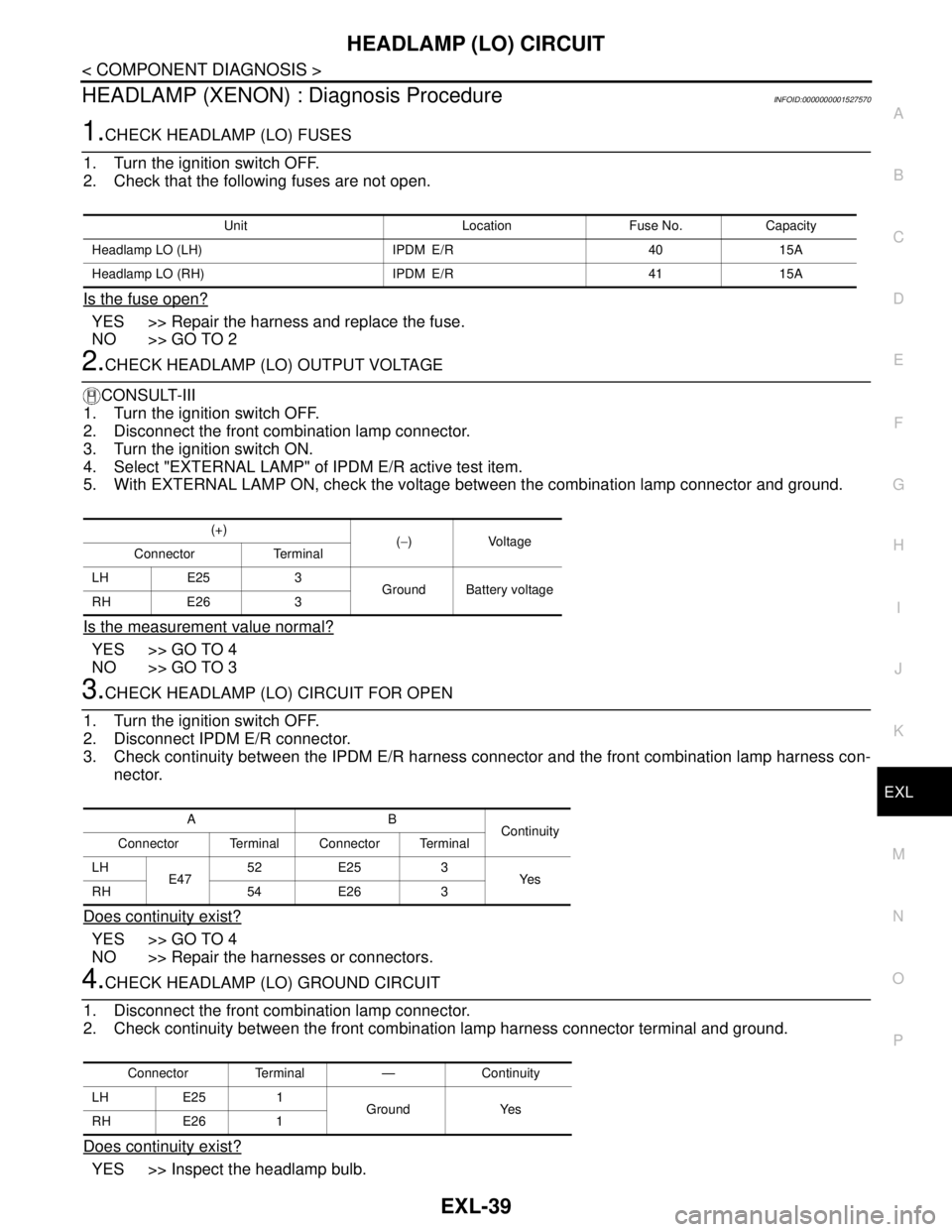
HEADLAMP (XENON) : Diagnosis ProcedureINFOID:0000000001527570
1.CHECK HEADLAMP (LO) FUSES
1. Turn the ignition switch OFF.
2. Check that the following fuses are not open.
Is the fuse open?
YES >> Repair the harness and replace the fuse.
NO >> GO TO 2
2.CHECK HEADLAMP (LO) OUTPUT VOLTAGE
CONSULT-III
1. Turn the ignition switch OFF.
2. Disconnect the front combination lamp connector.
3. Turn the ignition switch ON.
4. Select "EXTERNAL LAMP" of IPDM E/R active test item.
5. With EXTERNAL LAMP ON, check the voltage between the combination lamp connector and ground.
Is the measurement value normal?
YES >> GO TO 4
NO >> GO TO 3
3.CHECK HEADLAMP (LO) CIRCUIT FOR OPEN
1. Turn the ignition switch OFF.
2. Disconnect IPDM E/R connector.
3. Check continuity between the IPDM E/R harness connector and the front combination lamp harness con-
nector.
Does continuity exist?
YES >> GO TO 4
NO >> Repair the harnesses or connectors.
4.CHECK HEADLAMP (LO) GROUND CIRCUIT
1. Disconnect the front combination lamp connector.
2. Check continuity between the front combination lamp harness connector terminal and ground.
Does continuity exist?
YES >> Inspect the headlamp bulb.
Unit Location Fuse No. Capacity
Headlamp LO (LH) IPDM E/R 40 15A
Headlamp LO (RH) IPDM E/R 41 15A
(+)
(−)Voltage
Connector Terminal
LH E25 3
Ground Battery voltage
RH E26 3
AB
Continuity
Connector Terminal Connector Terminal
LH
E4752 E25 3
Ye s
RH 54 E26 3
Connector Terminal — Continuity
LH E25 1
Ground Yes
RH E26 1
Page 3042 of 5883
FRONT FOG LAMP CIRCUIT
EXL-41
< COMPONENT DIAGNOSIS >
C
D
E
F
G
H
I
J
K
MA
B
EXL
N
O
P
FRONT FOG LAMP CIRCUIT
DescriptionINFOID:0000000001523265
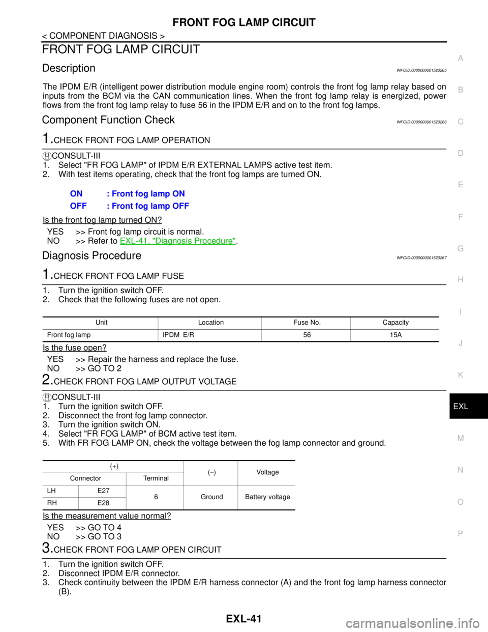
The IPDM E/R (intelligent power distribution module engine room) controls the front fog lamp relay based on
inputs from the BCM via the CAN communication lines. When the front fog lamp relay is energized, power
flows from the front fog lamp relay to fuse 56 in the IPDM E/R and on to the front fog lamps.
Component Function CheckINFOID:0000000001523266
1.CHECK FRONT FOG LAMP OPERATION
CONSULT-III
1. Select "FR FOG LAMP" of IPDM E/R EXTERNAL LAMPS active test item.
2. With test items operating, check that the front fog lamps are turned ON.
Is the front fog lamp turned ON?
YES >> Front fog lamp circuit is normal.
NO >> Refer to EXL-41, "
Diagnosis Procedure".
Diagnosis ProcedureINFOID:0000000001523267
1.CHECK FRONT FOG LAMP FUSE
1. Turn the ignition switch OFF.
2. Check that the following fuses are not open.
Is the fuse open?
YES >> Repair the harness and replace the fuse.
NO >> GO TO 2
2.CHECK FRONT FOG LAMP OUTPUT VOLTAGE
CONSULT-III
1. Turn the ignition switch OFF.
2. Disconnect the front fog lamp connector.
3. Turn the ignition switch ON.
4. Select "FR FOG LAMP" of BCM active test item.
5. With FR FOG LAMP ON, check the voltage between the fog lamp connector and ground.
Is the measurement value normal?
YES >> GO TO 4
NO >> GO TO 3
3.CHECK FRONT FOG LAMP OPEN CIRCUIT
1. Turn the ignition switch OFF.
2. Disconnect IPDM E/R connector.
3. Check continuity between the IPDM E/R harness connector (A) and the front fog lamp harness connector
(B).ON : Front fog lamp ON
OFF : Front fog lamp OFF
Unit Location Fuse No. Capacity
Front fog lamp IPDM E/R 56 15A
(+)
(−)Voltage
Connector Terminal
LH E27
6 Ground Battery voltage
RH E28
Page 3047 of 5883
EXL-46
< COMPONENT DIAGNOSIS >
PARKING LAMP CIRCUIT
PARKING LAMP CIRCUIT
WITH DAYTIME LIGHT SYSTEM
WITH DAYTIME LIGHT SYSTEM : DescriptionINFOID:0000000001523268
The IPDM E/R (Intelligent Power Distribution Module Engine Room) controls the daytime light relay based on
inputs from the BCM via the CAN communication lines. When the daytime light relay is energized power flows
to the front and rear combination lamps and the license plate lamps.
WITH DAYTIME LIGHT SYSTEM : Component Function CheckINFOID:0000000001523269
1.CHECK PARKING LAMP OPERATION
CONSULT-III
1. Select "TAIL LAMP" of IPDM E/R active test item.
2. With test items operating, check that the parking lamps are turned ON.
Is the parking lamp turned ON?
YES >> Parking lamp circuit is normal.
NO >> Refer to EXL-46, "
WITH DAYTIME LIGHT SYSTEM : Diagnosis Procedure".
WITH DAYTIME LIGHT SYSTEM : Diagnosis ProcedureINFOID:0000000001523270
1.CHECK PARKING LAMP FUSE
1. Turn the ignition switch OFF.
2. Check that the following fuse is not open.
Is the fuse open?
YES >> Repair the harness and replace the fuse.
NO >> GO TO 2
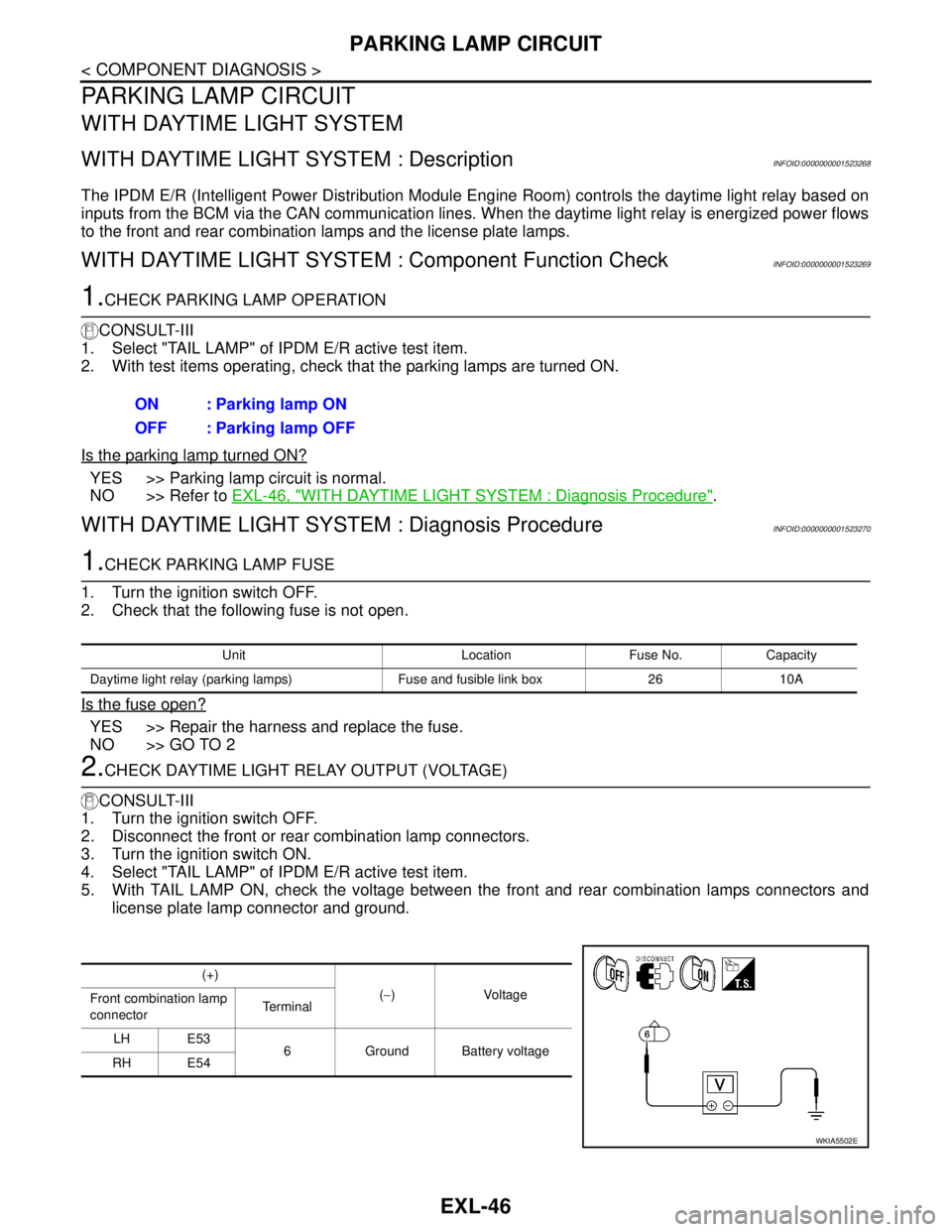
2.CHECK DAYTIME LIGHT RELAY OUTPUT (VOLTAGE)
CONSULT-III
1. Turn the ignition switch OFF.
2. Disconnect the front or rear combination lamp connectors.
3. Turn the ignition switch ON.
4. Select "TAIL LAMP" of IPDM E/R active test item.
5. With TAIL LAMP ON, check the voltage between the front and rear combination lamps connectors and
license plate lamp connector and ground.ON : Parking lamp ON
OFF : Parking lamp OFF
Unit Location Fuse No. Capacity
Daytime light relay (parking lamps) Fuse and fusible link box 26 10A
(+)
(−)Voltage
Front combination lamp
connectorTe r m i n a l
LH E53
6 Ground Battery voltage
RH E54
WKIA5502E
Page 3050 of 5883
PARKING LAMP CIRCUIT
EXL-49
< COMPONENT DIAGNOSIS >
C
D
E
F
G
H
I
J
K
MA
B
EXL
N
O
P
WITHOUT DAYTIME LIGHT SYSTEM : Diagnosis ProcedureINFOID:0000000001527577
1.CHECK PARKING LAMP FUSE
1. Turn the ignition switch OFF.
2. Check that the following fuse is not open.
Is the fuse open?
YES >> Repair the harness and replace the fuse.
NO >> GO TO 2
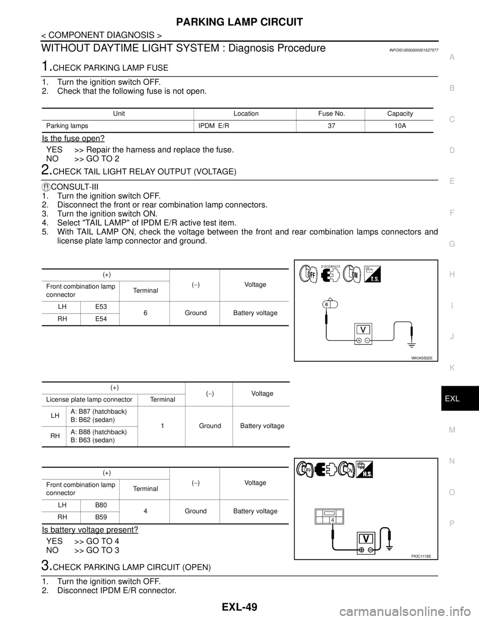
2.CHECK TAIL LIGHT RELAY OUTPUT (VOLTAGE)
CONSULT-III
1. Turn the ignition switch OFF.
2. Disconnect the front or rear combination lamp connectors.
3. Turn the ignition switch ON.
4. Select "TAIL LAMP" of IPDM E/R active test item.
5. With TAIL LAMP ON, check the voltage between the front and rear combination lamps connectors and
license plate lamp connector and ground.
Is battery voltage present?
YES >> GO TO 4
NO >> GO TO 3
3.CHECK PARKING LAMP CIRCUIT (OPEN)
1. Turn the ignition switch OFF.
2. Disconnect IPDM E/R connector.
Unit Location Fuse No. Capacity
Parking lamps IPDM E/R 37 10A
(+)
(−)Voltage
Front combination lamp
connectorTe r m i n a l
LH E53
6 Ground Battery voltage
RH E54
WKIA5502E
(+)
(−)Voltage
License plate lamp connector Terminal
LHA: B87 (hatchback)
B: B62 (sedan)
1 Ground Battery voltage
RHA: B88 (hatchback)
B: B63 (sedan)
(+)
(−)Voltage
Front combination lamp
connectorTe r m i n a l
LH B80
4 Ground Battery voltage
RH B59
P K I C 111 8 E
Page 3206 of 5883
GI-12
< HOW TO USE THIS MANUAL >
HOW TO USE THIS MANUAL
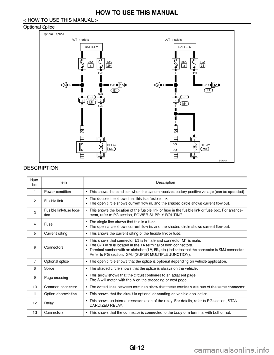
Optional Splice
DESCRIPTION
SGI942
Num-
berItem Description
1 Power condition This shows the condition when the system receives battery positive voltage (can be operated).
2Fusible link The double line shows that this is a fusible link.
The open circle shows current flow in, and the shaded circle shows current flow out.
3Fusible link/fuse loca-
tion This shows the location of the fusible link or fuse in the fusible link or fuse box. For arrange-
ment, refer to PG section, POWER SUPPLY ROUTING.
4Fuse The single line shows that this is a fuse.
The open circle shows current flow in, and the shaded circle shows current flow out.
5 Current rating This shows the current rating of the fusible link or fuse.
6 Connectors This shows that connector E3 is female and connector M1 is male.
The G/R wire is located in the 1A terminal of both connectors.
Terminal number with an alphabet (1A, 5B, etc.) indicates that the connector is SMJ connector.
Refer to PG section, SMJ (SUPER MULTIPLE JUNCTION).
7 Optional splice The open circle shows that the splice is optional depending on vehicle application.
8 Splice The shaded circle shows that the splice is always on the vehicle.
9 Page crossing This arrow shows that the circuit continues to an adjacent page.
The A will match with the A on the preceding or next page.
10 Common connector The dotted lines between terminals show that these terminals are part of the same connector.
11 Option abbreviation This shows that the circuit is optional depending on vehicle application.
12 Relay This shows an internal representation of the relay. For details, refer to PG section, STAN-
DARDIZED RELAY.
13 Connectors This shows that the connector is connected to the body or a terminal with bolt or nut.
Page 3217 of 5883
HOW TO READ WIRING DIAGRAMS
GI-23
< HOW TO USE THIS MANUAL >
C
D
E
F
G
H
I
J
K
L
MB
GI
N
O
P
DescriptionINFOID:0000000001691462
SWITCH POSITIONS
Switches are shown in wiring diagrams as if the vehicle is in the “normal” condition.
A vehicle is in the “normal” condition when:
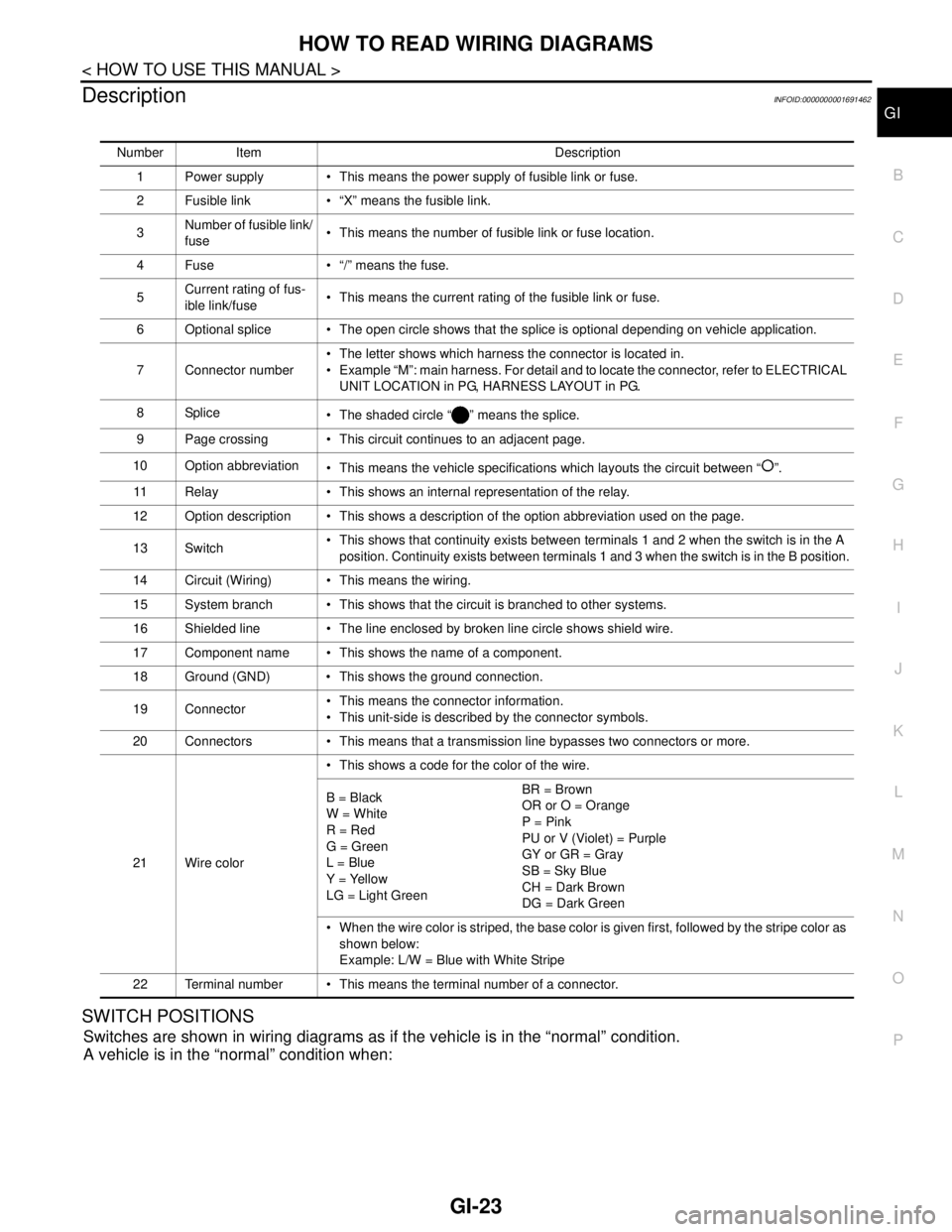
Number Item Description
1 Power supply This means the power supply of fusible link or fuse.
2 Fusible link “X” means the fusible link.
3Number of fusible link/
fuse This means the number of fusible link or fuse location.
4 Fuse “/” means the fuse.
5Current rating of fus-
ible link/fuse This means the current rating of the fusible link or fuse.
6 Optional splice The open circle shows that the splice is optional depending on vehicle application.
7 Connector number The letter shows which harness the connector is located in.
Example “M”: main harness. For detail and to locate the connector, refer to ELECTRICAL
UNIT LOCATION in PG, HARNESS LAYOUT in PG.
8Splice
The shaded circle “ ” means the splice.
9 Page crossing This circuit continues to an adjacent page.
10 Option abbreviation
This means the vehicle specifications which layouts the circuit between “ ”.
11 Relay This shows an internal representation of the relay.
12 Option description This shows a description of the option abbreviation used on the page.
13 Switch This shows that continuity exists between terminals 1 and 2 when the switch is in the A
position. Continuity exists between terminals 1 and 3 when the switch is in the B position.
14 Circuit (Wiring) This means the wiring.
15 System branch This shows that the circuit is branched to other systems.
16 Shielded line The line enclosed by broken line circle shows shield wire.
17 Component name This shows the name of a component.
18 Ground (GND) This shows the ground connection.
19 Connector This means the connector information.
This unit-side is described by the connector symbols.
20 Connectors This means that a transmission line bypasses two connectors or more.
21 Wire color This shows a code for the color of the wire.
B = Black
W = White
R = Red
G = Green
L = Blue
Y = Yellow
LG = Light GreenBR = Brown
OR or O = Orange
P = Pink
PU or V (Violet) = Purple
GY or GR = Gray
SB = Sky Blue
CH = Dark Brown
DG = Dark Green
When the wire color is striped, the base color is given first, followed by the stripe color as
shown below:
Example: L/W = Blue with White Stripe
22 Terminal number This means the terminal number of a connector.
Page 4306 of 5883
MIR-8
< REMOVAL AND INSTALLATION >
DOOR MIRROR
Disassembly and Assembly
INFOID:0000000001716809
DISASSEMBLY
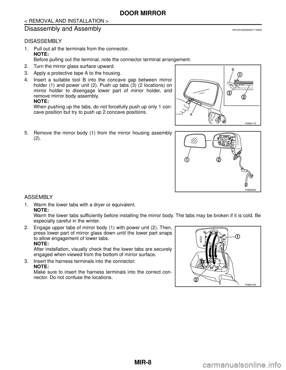
1. Pull out all the terminals from the connector.
NOTE:
Before pulling out the terminal, note the connector terminal arrangement.
2. Turn the mirror glass surface upward.
3. Apply a protective tape A to the housing.
4. Insert a suitable tool B into the concave gap between mirror
holder (1) and power unit (2). Push up tabs (3) (2 locations) on
mirror holder to disengage lower part of mirror holder, and
remove mirror body assembly.
NOTE:
When pushing up the tabs, do not forcefully push up only 1 con-
cave position but try to push up 2 concave positions.
5. Remove the mirror body (1) from the mirror housing assembly
(2).
ASSEMBLY
1. Warm the lower tabs with a dryer or equivalent.
NOTE:
Warm the lower tabs sufficiently before installing the mirror body. The tabs may be broken if it is cold. Be
especially careful in the winter.
2. Engage upper tabs of mirror body (1) with power unit (2). Then,
press lower part of mirror glass down until the lower part snaps
to allow engagement of lower tabs.
NOTE:
After installation, visually check that the lower tabs are securely
engaged when viewed from the bottom of mirror surface.
3. Insert the harness terminals into the connector.
NOTE:
Make sure to insert the harness terminals into the correct con-
nector. Do not confuse the locations.
PIIB6317E
PIIB6096E
PIIB6316E