Wiper NISSAN TIIDA 2007 Service Repair Manual
[x] Cancel search | Manufacturer: NISSAN, Model Year: 2007, Model line: TIIDA, Model: NISSAN TIIDA 2007Pages: 5883, PDF Size: 78.95 MB
Page 1 of 5883
MODEL C11 SERIES
2007 NISSAN EUROPE S.A.S.
All rights reserved. No part of this Electronic Service Manual may be reproduced or stored in a retrieval system, or transmitted in any form,
or by any means, electronic, mechanical, photocopying, recording or otherwise, without the prior written permission of Nissan Europe
S.A.S., Paris, France.
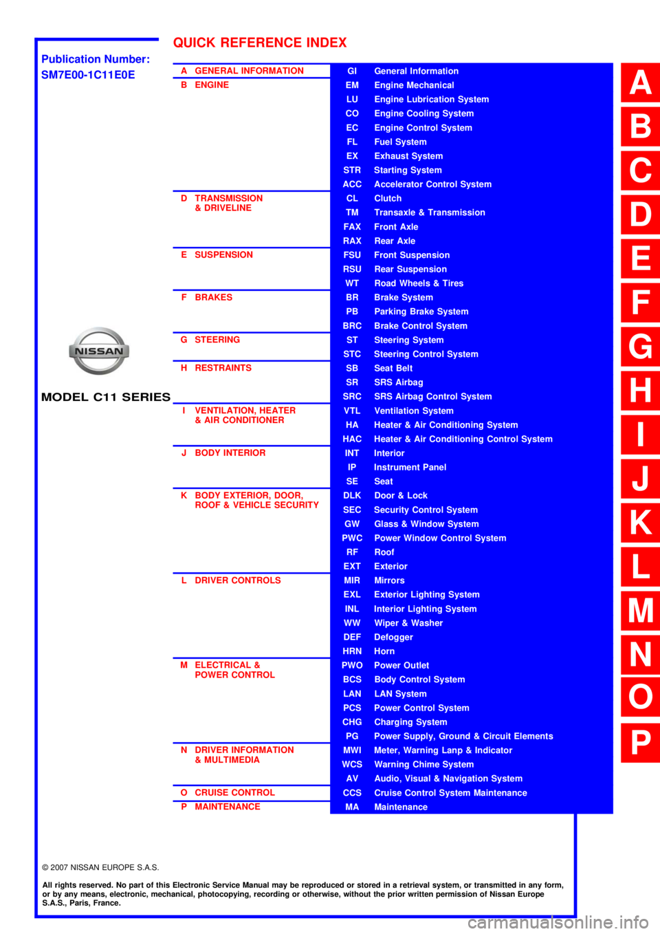
A GENERAL INFORMATION
B ENGINE
D TRANSMISSION& DRIVELINE
E SUSPENSION F BRAKES
G STEERING H RESTRAINTS
I VENTILATION, HEATER & AIR CONDITIONER
J BODY INTERIOR
K BODY EXTERIOR, DOOR, ROOF & VEHICLE SECURITY
L DRIVER CONTROLS
M ELECTRICAL & POWER CONTROL
N DRIVER INFORMATION & MULTIMEDIA
O CRUISE CONTROL P MAINTENANCEGI General Information
EM Engine Mechanical
LU Engine Lubrication System
CO Engine Cooling System
EC Engine Control System
FL Fuel System
EX Exhaust System
STR Starting System
ACC Accelerator Control System
CL Clutch
TM Transaxle & Transmission
FAX Front Axle
RAX Rear Axle
FSU Front Suspension
RSU Rear Suspension
WT Road Wheels & Tires
BR Brake System
PB Parking Brake System
BRC Brake Control System
ST Steering System
STC Steering Control System
SB Seat Belt
SR SRS Airbag
SRC SRS Airbag Control System
VTL Ventilation System
HA Heater & Air Conditioning System
HAC Heater & Air Conditioning Control System
INT Interior
IP Instrument Panel
SE Seat
DLK Door & Lock
SEC Security Control System
GW Glass & Window System
PWC Power Window Control System
RF Roof
EXT Exterior
MIR Mirrors
EXL Exterior Lighting System
INL Interior Lighting System
WW Wiper & Washer
DEF Defogger
HRN Horn
PWO Power Outlet
BCS Body Control System
LAN LAN System
PCS Power Control System
CHG Charging System
PG Power Supply, Ground & Circuit Elements
MWI Meter, Warning Lanp & Indicator
WCS Warning Chime System
AV Audio, Visual & Navigation System
CCS Cruise Control System Maintenance
MA Maintenance
QUICK REFERENCE INDEX
A
B
C
D
E
F
G
H
I
J
K
L
M
N
O
P
M
Publication Number:
SM7E00-1C11E0E
Page 136 of 5883
BCS
BCS-1
ELECTRICAL & POWER CONTROL
C
D
E
F
G
H
I
J
K
L B
SECTION BCS
A
O
P N
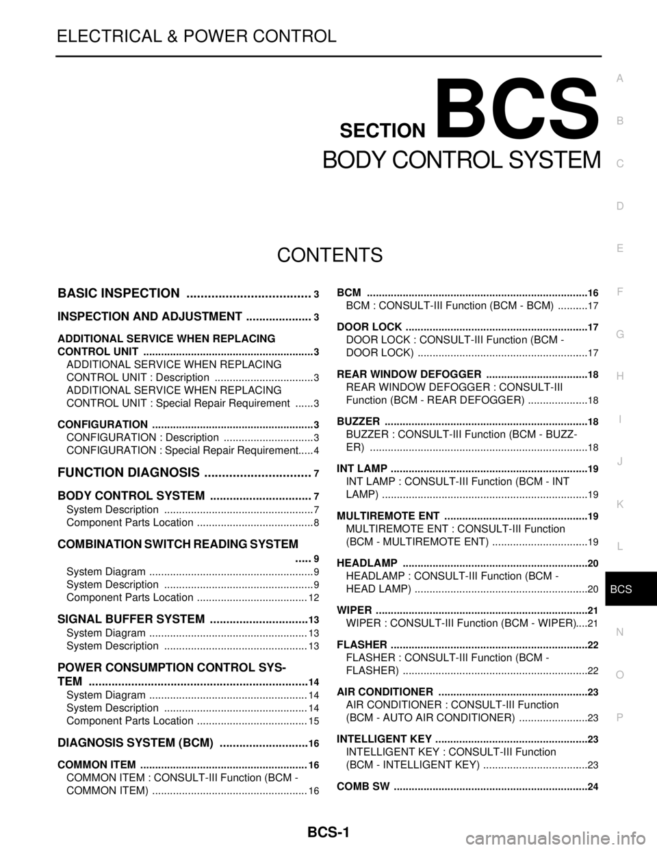
CONTENTS
BODY CONTROL SYSTEM
BASIC INSPECTION ....................................3
INSPECTION AND ADJUSTMENT .....................3
ADDITIONAL SERVICE WHEN REPLACING
CONTROL UNIT ..........................................................
3
ADDITIONAL SERVICE WHEN REPLACING
CONTROL UNIT : Description ..................................
3
ADDITIONAL SERVICE WHEN REPLACING
CONTROL UNIT : Special Repair Requirement .......
3
CONFIGURATION .......................................................3
CONFIGURATION : Description ...............................3
CONFIGURATION : Special Repair Requirement ......4
FUNCTION DIAGNOSIS ...............................7
BODY CONTROL SYSTEM ................................7
System Description ...................................................7
Component Parts Location ........................................8
COMBINATION SWITCH READING SYSTEM
.....
9
System Diagram ........................................................9
System Description ...................................................9
Component Parts Location ......................................12
SIGNAL BUFFER SYSTEM ...............................13
System Diagram ......................................................13
System Description .................................................13
POWER CONSUMPTION CONTROL SYS-
TEM ....................................................................
14
System Diagram ......................................................14
System Description .................................................14
Component Parts Location ......................................15
DIAGNOSIS SYSTEM (BCM) ............................16
COMMON ITEM .........................................................16
COMMON ITEM : CONSULT-III Function (BCM -
COMMON ITEM) .....................................................
16
BCM ...........................................................................16
BCM : CONSULT-III Function (BCM - BCM) ...........17
DOOR LOCK ..............................................................17
DOOR LOCK : CONSULT-III Function (BCM -
DOOR LOCK) ..........................................................
17
REAR WINDOW DEFOGGER ...................................18
REAR WINDOW DEFOGGER : CONSULT-III
Function (BCM - REAR DEFOGGER) .....................
18
BUZZER .....................................................................18
BUZZER : CONSULT-III Function (BCM - BUZZ-
ER) ..........................................................................
18
INT LAMP ...................................................................19
INT LAMP : CONSULT-III Function (BCM - INT
LAMP) ......................................................................
19
MULTIREMOTE ENT .................................................19
MULTIREMOTE ENT : CONSULT-III Function
(BCM - MULTIREMOTE ENT) .................................
19
HEADLAMP ...............................................................20
HEADLAMP : CONSULT-III Function (BCM -
HEAD LAMP) ...........................................................
20
WIPER ........................................................................21
WIPER : CONSULT-III Function (BCM - WIPER) ....21
FLASHER ...................................................................22
FLASHER : CONSULT-III Function (BCM -
FLASHER) ...............................................................
22
AIR CONDITIONER ...................................................23
AIR CONDITIONER : CONSULT-III Function
(BCM - AUTO AIR CONDITIONER) ........................
23
INTELLIGENT KEY ....................................................23
INTELLIGENT KEY : CONSULT-III Function
(BCM - INTELLIGENT KEY) ....................................
23
COMB SW ..................................................................24
Page 142 of 5883
BCS
BODY CONTROL SYSTEM
BCS-7
< FUNCTION DIAGNOSIS >
C
D
E
F
G
H
I
J
K
L B A
O
P N
FUNCTION DIAGNOSIS
BODY CONTROL SYSTEM
System DescriptionINFOID:0000000001451453
OUTLINE
BCM (Body Control Module) controls the various electrical components. It inputs the information required to
the control from CAN communication and the signal received from each switch and sensor.
BCM has combination switch reading function for reading the operation status of combination switches (light,
turn signal, wiper and washer) in addition to a function for controlling the operation of various electrical com-
ponents. It also has the signal transmission function as the passed point of signal and the power consump-
tion control function that reduces the power consumption with the ignition switch OFF.
BCM is equipped with the diagnosis function that performs the diagnosis with CONSULT-III and various set-
tings.
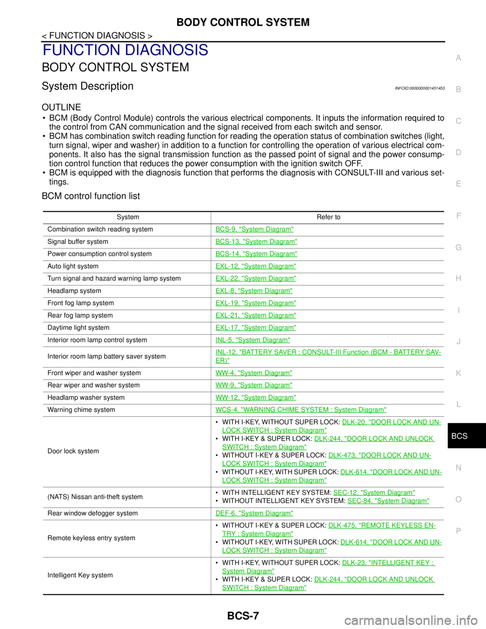
BCM control function list
System Refer to
Combination switch reading systemBCS-9, "
System Diagram"
Signal buffer systemBCS-13, "System Diagram"
Power consumption control systemBCS-14, "System Diagram"
Auto light systemEXL-12, "System Diagram"
Turn signal and hazard warning lamp systemEXL-22, "System Diagram"
Headlamp systemEXL-8, "System Diagram"
Front fog lamp systemEXL-19, "System Diagram"
Rear fog lamp systemEXL-21, "System Diagram"
Daytime light systemEXL-17, "System Diagram"
Interior room lamp control systemINL-5, "System Diagram"
Interior room lamp battery saver systemINL-12, "BATTERY SAVER : CONSULT-III Function (BCM - BATTERY SAV-
ER)"
Front wiper and washer systemWW-4, "System Diagram"
Rear wiper and washer systemWW-9, "System Diagram"
Headlamp washer systemWW-12, "System Diagram"
Warning chime systemWCS-4, "WARNING CHIME SYSTEM : System Diagram"
Door lock system WITH I-KEY, WITHOUT SUPER LOCK: DLK-20, "
DOOR LOCK AND UN-
LOCK SWITCH : System Diagram"
WITH I-KEY & SUPER LOCK: DLK-244, "DOOR LOCK AND UNLOCK
SWITCH : System Diagram"
WITHOUT I-KEY & SUPER LOCK: DLK-473, "DOOR LOCK AND UN-
LOCK SWITCH : System Diagram"
WITHOUT I-KEY, WITH SUPER LOCK: DLK-614, "DOOR LOCK AND UN-
LOCK SWITCH : System Diagram"
(NATS) Nissan anti-theft system WITH INTELLIGENT KEY SYSTEM: SEC-12, "System Diagram"
WITHOUT INTELLIGENT KEY SYSTEM: SEC-84, "System Diagram"
Rear window defogger systemDEF-6, "System Diagram"
Remote keyless entry system WITHOUT I-KEY & SUPER LOCK: DLK-475, "
REMOTE KEYLESS EN-
TRY : System Diagram"
WITHOUT I-KEY, WITH SUPER LOCK: DLK-614, "DOOR LOCK AND UN-
LOCK SWITCH : System Diagram"
Intelligent Key system WITH I-KEY, WITHOUT SUPER LOCK: DLK-23, "
INTELLIGENT KEY :
System Diagram"
WITH I-KEY & SUPER LOCK: DLK-244, "DOOR LOCK AND UNLOCK
SWITCH : System Diagram"
Page 144 of 5883
BCS
COMBINATION SWITCH READING SYSTEM
BCS-9
< FUNCTION DIAGNOSIS >
C
D
E
F
G
H
I
J
K
L B A
O
P N
COMBINATION SWITCH READING SYSTEM
System DiagramINFOID:0000000001451455
System DescriptionINFOID:0000000001451456
OUTLINE
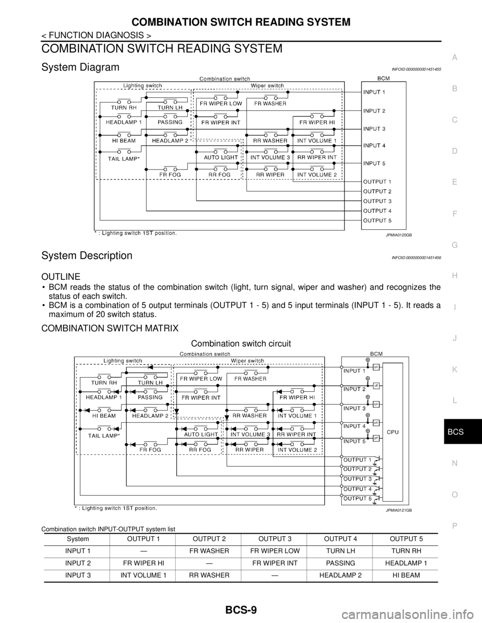
BCM reads the status of the combination switch (light, turn signal, wiper and washer) and recognizes the
status of each switch.
BCM is a combination of 5 output terminals (OUTPUT 1 - 5) and 5 input terminals (INPUT 1 - 5). It reads a
maximum of 20 switch status.
COMBINATION SWITCH MATRIX
Combination switch circuit
Combination switch INPUT-OUTPUT system list
JPMIA0120GB
System OUTPUT 1 OUTPUT 2 OUTPUT 3 OUTPUT 4 OUTPUT 5
INPUT 1 — FR WASHER FR WIPER LOW TURN LH TURN RH
INPUT 2 FR WIPER HI — FR WIPER INT PASSING HEADLAMP 1
INPUT 3 INT VOLUME 1 RR WASHER — HEADLAMP 2 HI BEAM
JPMIA0121GB
Page 145 of 5883
BCS-10
< FUNCTION DIAGNOSIS >
COMBINATION SWITCH READING SYSTEM
NOTE:
Headlamp has a dual system switch.
COMBINATION SWITCH READING FUNCTION
Description
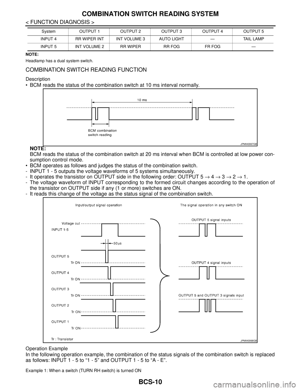
BCM reads the status of the combination switch at 10 ms interval normally.
NOTE:
BCM reads the status of the combination switch at 20 ms interval when BCM is controlled at low power con-
sumption control mode.
BCM operates as follows and judges the status of the combination switch.
- INPUT 1 - 5 outputs the voltage waveforms of 5 systems simultaneously.
- It operates the transistor on OUTPUT side in the following order: OUTPUT 5 → 4 → 3 → 2 → 1.
- The voltage waveform of INPUT corresponding to the formed circuit changes according to the operation of
the transistor on OUTPUT side if any (1 or more) switches are ON.
- It reads this change of the voltage as the status signal of the combination switch.
Operation Example
In the following operation example, the combination of the status signals of the combination switch is replaced
as follows: INPUT 1 - 5 to “1 - 5” and OUTPUT 1 - 5 to “A - E”.
Example 1: When a switch (TURN RH switch) is turned ON
INPUT 4 RR WIPER INT INT VOLUME 3 AUTO LIGHT — TAIL LAMP
INPUT 5 INT VOLUME 2 RR WIPER RR FOG FR FOG —System OUTPUT 1 OUTPUT 2 OUTPUT 3 OUTPUT 4 OUTPUT 5
JPMIA0067GB
JPMIA0068GB
Page 146 of 5883
BCS
COMBINATION SWITCH READING SYSTEM
BCS-11
< FUNCTION DIAGNOSIS >
C
D
E
F
G
H
I
J
K
L B A
O
P N
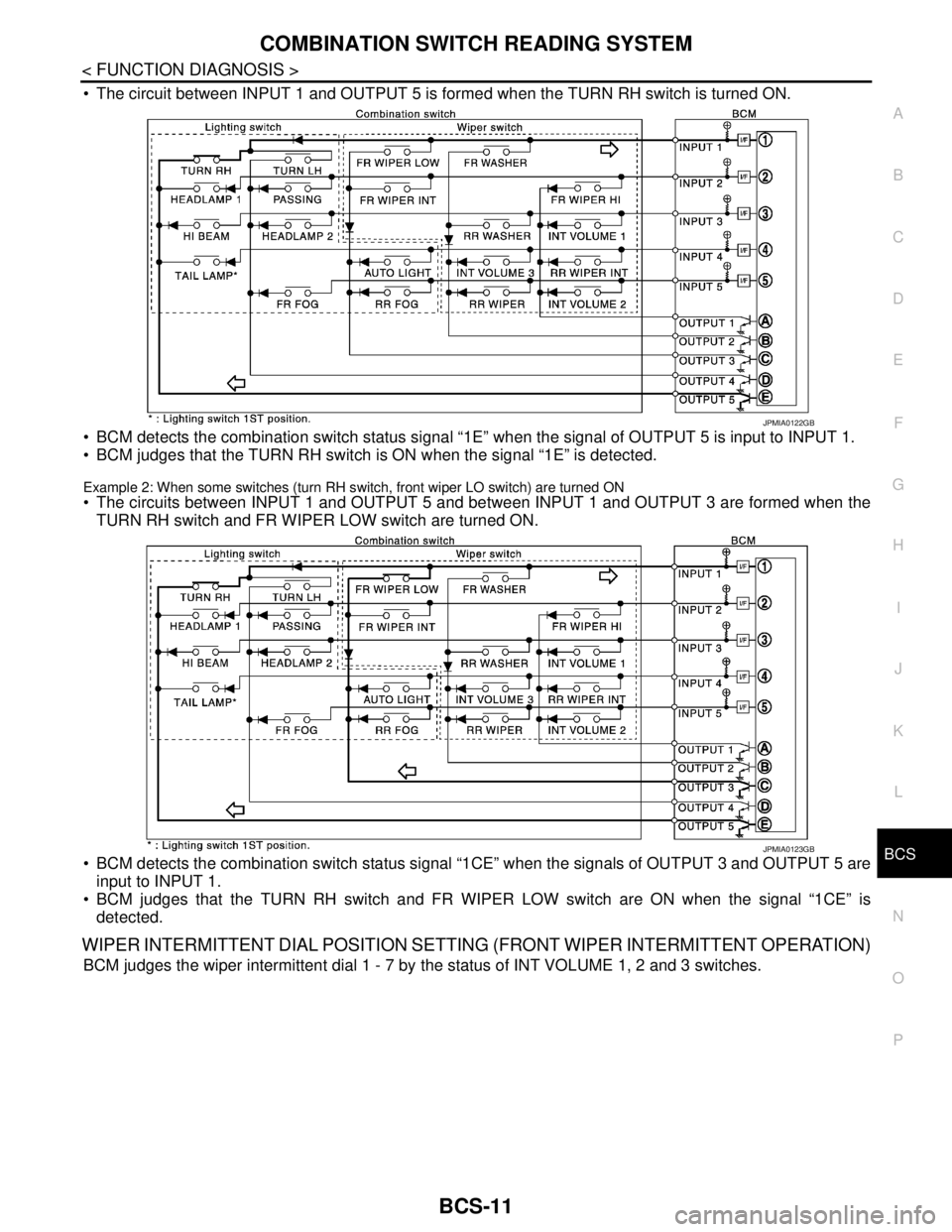
The circuit between INPUT 1 and OUTPUT 5 is formed when the TURN RH switch is turned ON.
BCM detects the combination switch status signal “1E” when the signal of OUTPUT 5 is input to INPUT 1.
BCM judges that the TURN RH switch is ON when the signal “1E” is detected.
Example 2: When some switches (turn RH switch, front wiper LO switch) are turned ON
The circuits between INPUT 1 and OUTPUT 5 and between INPUT 1 and OUTPUT 3 are formed when the
TURN RH switch and FR WIPER LOW switch are turned ON.
BCM detects the combination switch status signal “1CE” when the signals of OUTPUT 3 and OUTPUT 5 are
input to INPUT 1.
BCM judges that the TURN RH switch and FR WIPER LOW switch are ON when the signal “1CE” is
detected.
WIPER INTERMITTENT DIAL POSITION SETTING (FRONT WIPER INTERMITTENT OPERATION)
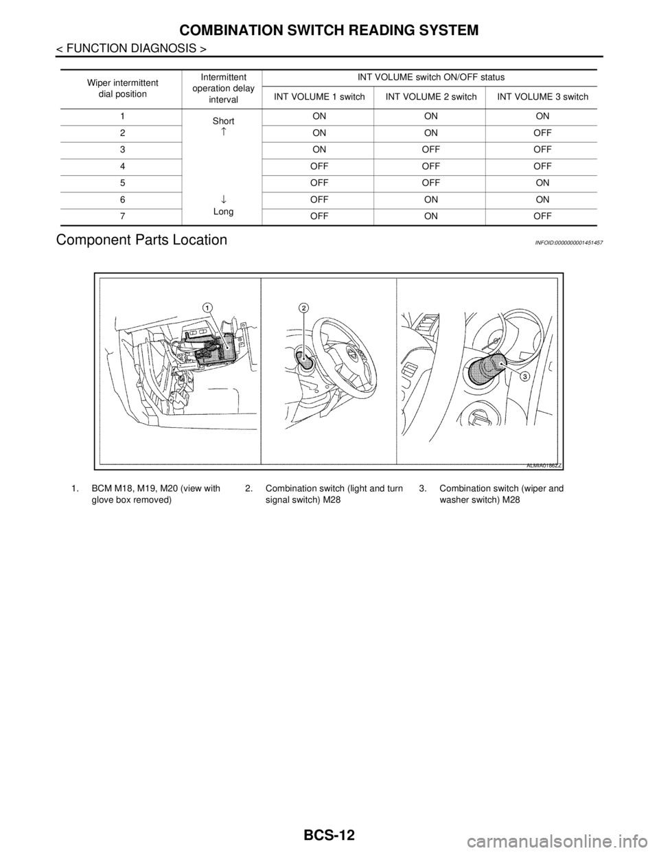
BCM judges the wiper intermittent dial 1 - 7 by the status of INT VOLUME 1, 2 and 3 switches.
JPMIA0122GB
JPMIA0123GB
Page 147 of 5883
BCS-12
< FUNCTION DIAGNOSIS >
COMBINATION SWITCH READING SYSTEM
Component Parts Location
INFOID:0000000001451457
Wiper intermittent
dial positionIntermittent
operation delay
intervalINT VOLUME switch ON/OFF status
INT VOLUME 1 switch INT VOLUME 2 switch INT VOLUME 3 switch
1
Short
↑
↓
LongON ON ON
2ONONOFF
3ONOFFOFF
4 OFF OFF OFF
5OFFOFFON
6 OFF ON ON
7 OFF ON OFF
1. BCM M18, M19, M20 (view with
glove box removed)2. Combination switch (light and turn
signal switch) M283. Combination switch (wiper and
washer switch) M28
ALMIA0186ZZ
Page 151 of 5883

BCS-16
< FUNCTION DIAGNOSIS >
DIAGNOSIS SYSTEM (BCM)
DIAGNOSIS SYSTEM (BCM)
COMMON ITEM
COMMON ITEM : CONSULT-III Function (BCM - COMMON ITEM)INFOID:0000000001451463
APPLICATION ITEM
CONSULT-III performs the following functions via CAN communication with BCM.
SYSTEM APPLICATION
BCM can perform the following functions for each system.
NOTE:
It can perform the diagnosis modes except the following for all sub system selection items.
1: With remote keyless entry system
2: With Intelligent Key
BCM
Diagnosis mode Function Description
WORK SUPPORT Changes the setting for each system function.
SELF-DIAG RESULTS Displays the diagnosis results judged by BCM. Refer to BCS-54, "
DTCIndex".
CAN DIAG SUPPORT MNTR Monitors the reception status of CAN communication viewed from BCM.
DATA MONITOR The BCM input/output signals are displayed.
ACTIVE TEST The signals used to activate each device are forcibly supplied from BCM.
ECU IDENTIFICATION The BCM part number is displayed.
CONFIGURATION Enables to read and save the vehicle specification.
Enables to write the vehicle specification when replacing BCM.
System Sub system selection itemDiagnosis mode
WORK SUPPORT DATA MONITOR ACTIVE TEST
BCM BCM×
Door lock DOOR LOCK×××
Rear window defogger REAR DEFOGGER××
Warning chime BUZZER××
Interior room lamp timer INT LAMP×××
Remote keyless entry system
1MULTI REMOTE ENT×××
Exterior lamp HEAD LAMP×××
Wiper and washer WIPER×××
Turn signal and hazard warning lamps FLASHER××
Air conditioner AIR CONDITONER×
Intelligent Key system
2INTELLIGENT KEY×
Combination switch COMB SW×
Immobilizer IMMU××
Interior room lamp battery saver BATTERY SAVER×××
Trunk open (sedan)/Back door open
(hatch back)DOOR LOCK××
Vehicle security system THEFT ALM×××
Signal buffer system SIGNAL BUFFER××
PTC heater system PTC HEATER××
Page 156 of 5883
BCS
DIAGNOSIS SYSTEM (BCM)
BCS-21
< FUNCTION DIAGNOSIS >
C
D
E
F
G
H
I
J
K
L B A
O
P N
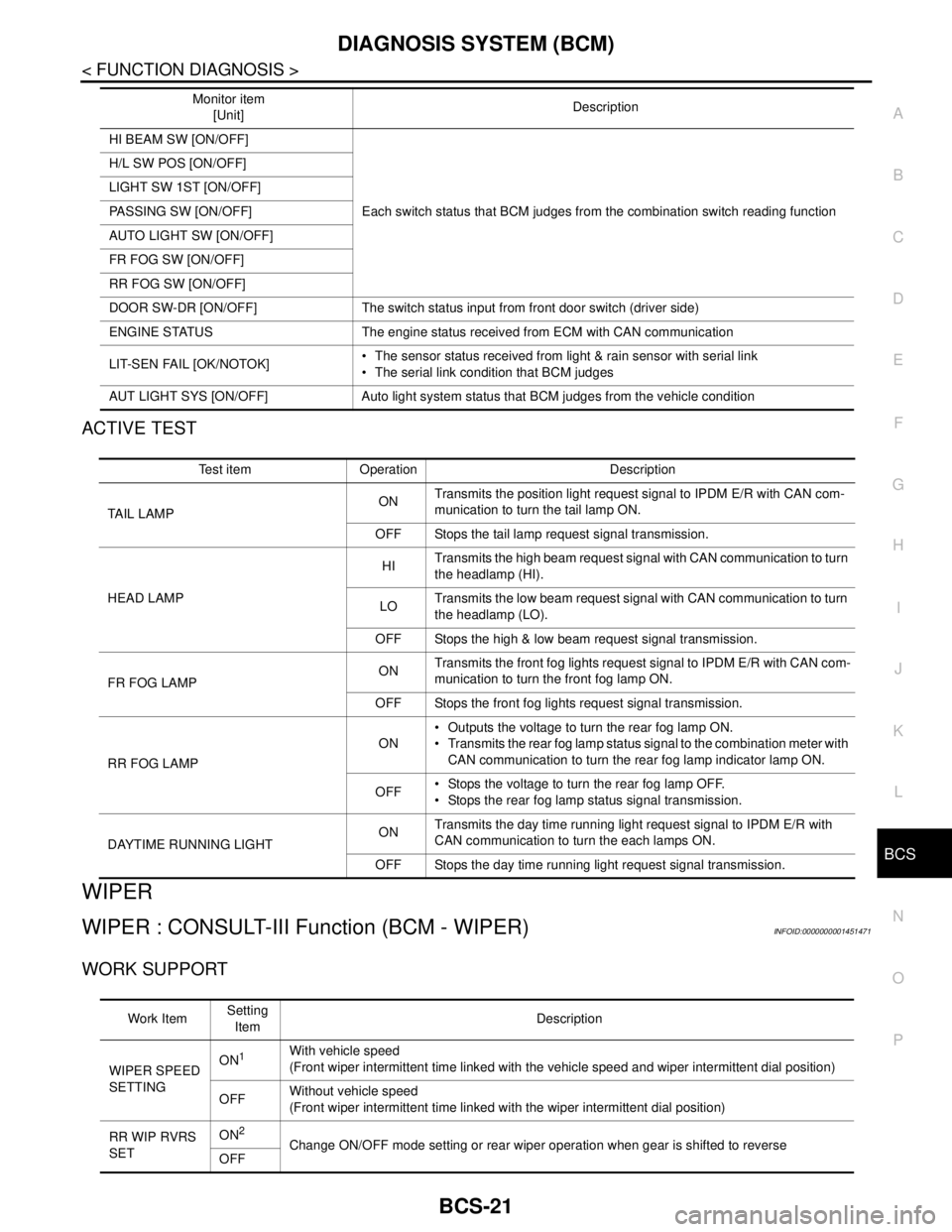
ACTIVE TEST
WIPER
WIPER : CONSULT-III Function (BCM - WIPER)INFOID:0000000001451471
WORK SUPPORT
HI BEAM SW [ON/OFF]
Each switch status that BCM judges from the combination switch reading function H/L SW POS [ON/OFF]
LIGHT SW 1ST [ON/OFF]
PASSING SW [ON/OFF]
AUTO LIGHT SW [ON/OFF]
FR FOG SW [ON/OFF]
RR FOG SW [ON/OFF]
DOOR SW-DR [ON/OFF] The switch status input from front door switch (driver side)
ENGINE STATUS The engine status received from ECM with CAN communication
LIT-SEN FAIL [OK/NOTOK] The sensor status received from light & rain sensor with serial link
The serial link condition that BCM judges
AUT LIGHT SYS [ON/OFF] Auto light system status that BCM judges from the vehicle conditionMonitor item
[Unit]Description
Test item Operation Description
TAIL LAMPONTransmits the position light request signal to IPDM E/R with CAN com-
munication to turn the tail lamp ON.
OFF Stops the tail lamp request signal transmission.
HEAD LAMPHITransmits the high beam request signal with CAN communication to turn
the headlamp (HI).
LOTransmits the low beam request signal with CAN communication to turn
the headlamp (LO).
OFF Stops the high & low beam request signal transmission.
FR FOG LAMPONTransmits the front fog lights request signal to IPDM E/R with CAN com-
munication to turn the front fog lamp ON.
OFF Stops the front fog lights request signal transmission.
RR FOG LAMPON Outputs the voltage to turn the rear fog lamp ON.
Transmits the rear fog lamp status signal to the combination meter with
CAN communication to turn the rear fog lamp indicator lamp ON.
OFF Stops the voltage to turn the rear fog lamp OFF.
Stops the rear fog lamp status signal transmission.
DAYTIME RUNNING LIGHTONTransmits the day time running light request signal to IPDM E/R with
CAN communication to turn the each lamps ON.
OFF Stops the day time running light request signal transmission.
Work ItemSetting
ItemDescription
WIPER SPEED
SETTINGON
1With vehicle speed
(Front wiper intermittent time linked with the vehicle speed and wiper intermittent dial position)
OFFWithout vehicle speed
(Front wiper intermittent time linked with the wiper intermittent dial position)
RR WIP RVRS
SETON
2Change ON/OFF mode setting or rear wiper operation when gear is shifted to reverse
OFF
Page 157 of 5883

BCS-22
< FUNCTION DIAGNOSIS >
DIAGNOSIS SYSTEM (BCM)
1: Factory setting
2: If equipped
DATA MONITOR
ACTIVE TEST
FLASHER
FLASHER : CONSULT-III Function (BCM - FLASHER)INFOID:0000000001451472
WORK SUPPORT
DATA MONITOR
Monitor Item
[Unit]Description
IGN ON SW [ON/OFF] Ignition switch ON status judged from ignition power supply.
FR WIPER HI [ON/OFF]
Each switch status that BCM judges from the combination switch reading function. FR WIPER LOW [ON/OFF]
FR WIPER INT [ON/OFF]
FR WASHER SW [ON/OFF]
INT VOLUME [1 - 7] Each switch status that BCM judges from the combination switch reading function.
FR WIPER STOP [ON/OFF]Front wiper motor (stop position) status received from IPDM E/R with CAN communica-
tion.
VEHICLE SPEED [km/h]The value of the vehicle speed signal received from combination meter with CAN com-
munication.
H/L SW POS [ON/OFF]
RR WIPER ON [ON/OFF]
Each switch status that BCM judges from the combination switch reading function. RR WIPER INT [ON/OFF]
RR WASHER SW [ON/OFF]
RR WIPER STOP [ON/OFF] Rear wiper motor (stop position) status input from the rear wiper motor.
REVERSE SW CAN [ON/OFF] Transmission reverse position moitored via CAN.
Test Item Operation Description
HEADLAMP WASH-
ERONTransmits the headlamp washer request signal to IPDM E/R with CAN communication to
operate the headlamp washer operation.
FR WIPERHITransmits the front wiper request signal (HI) to IPDM E/R with CAN communication to op-
erate the front wiper HI operation.
LOTransmits the front wiper request signal (LO) to IPDM E/R with CAN communication to
operate the front wiper LO operation.
INTTransmits the front wiper request signal (INT) to IPDM E/R with CAN communication to
operate the front wiper INT operation.
OFF Stops transmitting the front wiper request signal to stop the front wiper operation.
RR WIPERON Outputs the voltage to operate the rear wiper motor.
OFF Stops the voltage to stop.
Work Item Description
HAZARD LAMP SETOperation MODE1 MODE2 MODE3
MODE4
Keyfob operation Lock Unlock Lock Unlock Lock Unlock Lock Unlock
Hazard lamp flash - - - Twice Once - Once Twice